Static NAT
Static NAT maps network traffic from a static external IP address to an internal IP address or network. It creates a static translation of real addresses to mapped addresses. Static NAT provides internet connectivity to networking devices through a private LAN with an unregistered private IP address.
Understanding Static NAT
Static NAT defines a one-to-one mapping from one IP subnet to another IP subnet. The mapping includes destination IP address translation in one direction and source IP address translation in the reverse direction. From the NAT device, the original destination address is the virtual host IP address while the mapped-to address is the real host IP address.
Static NAT allows connections to be originated from either side of the network, but translation is limited to one-to-one or between blocks of addresses of the same size. For each private address, a public address must be allocated. No address pools are necessary.
Static NAT also supports the following types of translation:
To map multiple IP addresses and specified ranges of ports to a same IP address and different range of ports
To map a specific IP address and port to a different IP address and port
The port address translation (PAT) is also supported by giving static mapping between destination-port (range) and mapped-port (range).
The original destination address, along with other addresses in source and destination NAT pools, must not overlap within the same routing instance.
In NAT rule lookup, static NAT rules take precedence over destination NAT rules and reverse mapping of static NAT rules take precedence over source NAT rules.
Understanding Static NAT Rules
Static Network Address Translation (NAT) rules specify two layers of match conditions:
Traffic direction—Allows you to specify from interface, from zone, or from routing-instance.
Packet information—Can be source addresses and ports, and destination addresses and ports.
For all ALG traffic, except FTP, we recommend that you not use
the static NAT rule options source-address or source-port. Data session creation can fail if these options are used because
the IP address and the source port value, which is a random value,
might not match the static NAT rule. For FTP ALG traffic, the source-address option can be used because an IP address can
be provided to match the source address of a static NAT rule.
When both source and destination addresses are configured as match conditions for a rule, traffic is matched to both the source address and destination address. Because static NAT is bidirectional, traffic in the opposite direction reverse matches the rule, and the destination address of the traffic is matched to the configured source address.
If multiple static NAT rules overlap in the match conditions, the most specific rule is chosen. For example, if rules A and B specify the same source and destination IP addresses, but rule A specifies traffic from zone 1 and rule B specifies traffic from interface ge-0/0/0, rule B is used to perform static NAT. An interface match is considered to be more specific than a zone match, which is more specific than a routing instance match.
Because static NAT rules do not support overlapping addresses and ports, they should not be used to map one external IP address to multiple internal IP addresses for ALG traffic. For example, if different sites want to access two different FTP servers, the internal FTP servers should be mapped to two different external IP addresses.
For the static NAT rule action, specify the translated address and (optionally) the routing instance.
In NAT lookup, static NAT rules take precedence over destination NAT rules and reverse mapping of static NAT rules takes precedence over source NAT rules.
Static NAT Configuration Overview
The main configuration tasks for static NAT are as follows:
- Configure static NAT rules that align with your network and security requirements.
- Configure NAT proxy ARP entries for IP addresses in the same subnet of the ingress interface.
Example: Configuring Static NAT for Single Address Translation
This example describes how to configure a static NAT mapping of a single private address to a public address.
Requirements
Before you begin:
Configure network interfaces on the device. See Interfaces User Guide for Security Devices.
Create security zones and assign interfaces to them. See Understanding Security Zones.
Overview
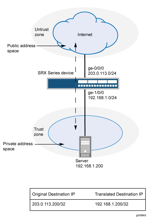
This example uses the trust security zone for the private address space and the untrust security zone for the public address space.
In Figure 1, devices in the untrust zone access a server in the trust zone by way of public address 203.0.113.200/32. For packets that enter the Juniper Networks security device from the untrust zone with the destination IP address 203.0.113.200/32, the destination IP address is translated to the private address 192.168.1.200/32. For a new session originating from the server, the source IP address in the outgoing packet is translated to the public address 203.0.113.200/32.
This example describes the following configurations:
Static NAT rule set
rs1with ruler1to match packets from the untrust zone with the destination address 203.0.113.200/32. For matching packets, the destination IP address is translated to the private address 192.168.1.200/32.Proxy ARP for the address 203.0.113.200 on interface ge-0/0/0.0. This allows the Juniper Networks security device to respond to ARP requests received on the interface for that address.
Security policies to permit traffic to and from the 192.168.1.200 server.
Configuration
Procedure
CLI Quick Configuration
To quickly configure this example, copy the
following commands, paste them into a text file, remove any line breaks,
change any details necessary to match your network configuration,
copy and paste the commands into the CLI at the [edit] hierarchy
level, and then enter commit from configuration mode.
set security nat static rule-set rs1 from zone untrust
set security nat static rule-set rs1 rule r1 match destination-address 203.0.113.200/32
set security nat static rule-set rs1 rule r1 then static-nat prefix 192.168.1.200/32
set security nat proxy-arp interface ge-0/0/0.0 address 203.0.113.200/32
set security address-book global address server-1 192.168.1.200/32
set security policies from-zone trust to-zone untrust policy permit-all match source-address server-1
set security policies from-zone trust to-zone untrust policy permit-all match destination-address any
set security policies from-zone trust to-zone untrust policy permit-all match application any
set security policies from-zone trust to-zone untrust policy permit-all then permit
set security policies from-zone untrust to-zone trust policy server-access match source-address any
set security policies from-zone untrust to-zone trust policy server-access match destination-address server-1
set security policies from-zone untrust to-zone trust policy server-access match application any
set security policies from-zone untrust to-zone trust policy server-access then permit
Step-by-Step Procedure
The following example requires you to navigate throughout various levels in the configuration hierarchy. For instructions on how to do that, see Using the CLI Editor in Configuration Mode.
To configure a static NAT mapping from a private address to a public address:
Create a static NAT rule set.
[edit security nat static]
user@host# set rule-set rs1 from zone untrust
Configure a rule that matches packets and translates the destination address in the packets to a private address.
[edit security nat static]
user@host# set rule-set rs1 rule r1 match destination-address 203.0.113.200/32
user@host# set rule-set rs1 rule r1 then static-nat prefix 192.168.1.200/32
Configure proxy ARP.
[edit security nat]
user@host# set proxy-arp interface ge-0/0/0.0 address 203.0.113.200
Configure an address in the global address book.
[edit security address-book global]
user@host# set address server-1 192.168.1.200/32
Configure a security policy that allows traffic from the untrust zone to the server in the trust zone.
[edit security policies from-zone untrust to-zone trust]
user@host# set policy server-access match source-address any destination-address server-1 application any
user@host# set policy server-access then permit
Configure a security policy that allows all traffic from the server in the trust zone to the untrust zone.
[edit security policies from-zone trust to-zone untrust]
user@host# set policy permit-all match source-address server-1 destination-address any application any
user@host# set policy permit-all then permit
Results
From configuration mode, confirm your configuration
by entering the show security nat and show security
policies commands. If the output does not display the intended
configuration, repeat the configuration instructions in this example
to correct it.
[edit]
user@host# show security nat
static {
    rule-set rs1 {
        from zone untrust;
        rule r1 {
            match {
                destination-address 203.0.113.200/32;
            }
            then {
                static-nat prefix 192.168.1.200/32;
            }
        }
    }
}
    proxy-arp {
        interface ge-0/0/0.0 {
            address {
                203.0.113.200/32;
            }
        }
    }
user@host# show security policies
    from-zone trust to-zone untrust {
        policy permit-all {
            match {
                source-address server-1;
                destination-address any;
                application any;
            }
            then {
                permit;
            }
        }
    }
    from-zone untrust to-zone trust {
        policy server-access {
            match {
                source-address any;
                destination-address server-1;
                application any;
            }
            then {
                permit;
            }
        }
    }
If you are done configuring the device, enter commit from configuration mode.
Verification
To confirm that the configuration is working properly, perform these tasks:
Verifying Static NAT Configuration
Purpose
Verify that there is traffic matching the static NAT rule set.
Action
From operational mode, enter the show security
nat static rule command. View the Translation hits field to
check for traffic that matches the rule.
Example: Configuring Static NAT for Subnet Translation
This example describes how to configure a static NAT mapping of a private subnet address to a public subnet address.
Address blocks for static NAT mapping must be of the same size.
Requirements
Before you begin:
Configure network interfaces on the device. See Interfaces User Guide for Security Devices.
Create security zones and assign interfaces to them. See Understanding Security Zones.
Overview
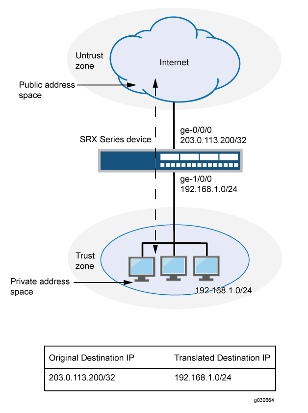
This example uses the trust security zone for the private address space and the untrust security zone for the public address space. In Figure 2, devices in the untrust zone access devices in the trust zone by way of public subnet address 203.0.113.0/24. For packets that enter the Juniper Networks security device from the untrust zone with a destination IP address in the 203.0.113.0/24 subnet, the destination IP address is translated to a private address on the 192.168.1.0/24 subnet. For new sessions originating from the 192.168.1.0/24 subnet, the source IP address in outgoing packets is translated to an address on the public 203.0.113.0/24 subnet.
This example describes the following configurations:
Static NAT rule set
rs1with ruler1to match packets received on interface ge-0/0/0.0 with a destination IP address in the 203.0.113.0/24 subnet. For matching packets, the destination address is translated to an address on the 192.168.1.0/24 subnet.Proxy ARP for the address ranges 203.0.113.1/32 through 203.0.113.249/32 on interface ge-0/0/0.0. This allows the Juniper Networks security device to respond to ARP requests received on the interface for those addresses. The address 203.0.113.250/32 is assigned to the interface itself, so this address is not included in the proxy ARP configuration.
Security policies to permit traffic to and from the 192.168.1.0/24 subnet.
Configuration
Procedure
CLI Quick Configuration
To quickly configure this example, copy the
following commands, paste them into a text file, remove any line breaks,
change any details necessary to match your network configuration,
copy and paste the commands into the CLI at the [edit] hierarchy
level, and then enter commit from configuration mode.
set security nat static rule-set rs1 from interface ge-0/0/0.0 set security nat static rule-set rs1 rule r1 match destination-address 203.0.113.0/24 set security nat static rule-set rs1 rule r1 then static-nat prefix 192.168.1.0/24 set security nat proxy-arp interface ge-0/0/0.0 address 203.0.113.1/32 to 203.0.113.249/32 set security address-book global address server-group 192.168.1.0/24 set security policies from-zone trust to-zone untrust policy permit-all match source-address server-group set security policies from-zone trust to-zone untrust policy permit-all match destination-address any set security policies from-zone trust to-zone untrust policy permit-all match application any set security policies from-zone trust to-zone untrust policy permit-all then permit set security policies from-zone untrust to-zone trust policy server-access match source-address any set security policies from-zone untrust to-zone trust policy server-access match destination-address server-group set security policies from-zone untrust to-zone trust policy server-access match application any set security policies from-zone untrust to-zone trust policy server-access then permit
Step-by-Step Procedure
The following example requires you to navigate throughout various levels in the configuration hierarchy. For instructions on how to do that, see Using the CLI Editor in Configuration Mode.
To configure a static NAT mapping from a private subnet address to a public subnet address:
Create a static NAT rule set.
[edit security nat static] user@host# set rule-set rs1 from interface ge-0/0/0.0
Configure a rule that matches packets and translates the destination address in the packets to an address in a private subnet.
[edit security nat static] user@host# set rule-set rs1 rule r1 match destination-address 203.0.113.0/24 user@host# set rule-set rs1 rule r1 then static-nat prefix 192.168.1.0/24
Configure proxy ARP.
[edit security nat] user@host# set proxy-arp interface ge-0/0/0.0 address 203.0.113.1/32 to 203.0.113.249/32
Configure an address in the global address book.
[edit security address-book global] user@host# set address server-group 192.168.1.0/24
Configure a security policy that allows traffic from the untrust zone to the subnet in the trust zone.
[edit security policies from-zone untrust to-zone trust] user@host# set policy server-access match source-address any destination-address server-group application any user@host# set policy server-access then permit
Configure a security policy that allows all traffic from the subnet in the trust zone to the untrust zone.
[edit security policies from-zone trust to-zone untrust] user@host# set policy permit-all match source-address server-group destination-address any application any user@host# set policy permit-all then permit
Results
From configuration mode, confirm your configuration
by entering the show security nat and show security
policies commands. If the output does not display the intended
configuration, repeat the configuration instructions in this example
to correct it.
[edit]
user@host# show security nat
static {
rule-set rs1 {
from interface ge-0/0/0.0;
rule r1 {
match {
destination-address 203.0.113.0/24;
}
then {
static-nat prefix 192.168.1.0/24;
}
}
}
}
proxy-arp {
interface ge-0/0/0.0 {
address {
203.0.113.1/32 to 203.0.113.249/32;
}
}
}
user@host# show security policies
from-zone trust to-zone untrust {
policy permit-all {
match {
source-address server-group;
destination-address any;
application any;
}
then {
permit;
}
}
}
from-zone untrust to-zone trust {
policy server-access {
match {
source-address any;
destination-address server-group;
application any;
}
then {
permit;
}
}
}
If you are done configuring the device, enter commit from configuration mode.
Verification
To confirm that the configuration is working properly, perform these tasks:
Verifying Static NAT Configuration
Purpose
Verify that there is traffic matching the static NAT rule set.
Action
From operational mode, enter the show security
nat static rule command. View the Translation hits field to
check for traffic that matches the rule.
Example: Configuring Static NAT64 for Subnet Translation
Use this configuration example to configure static NAT64 to enable seamless translation between IPv6 and IPv4 address spaces. You can use static NAT64 in environments transitioning from IPv4 to IPv6 to ensure reliable cross-IP version communication.
|
Readability Score |
|
|
Reading Time |
Less than 15 minutes. |
|
Configuration Time |
Less than an hour. |
- Example Prerequisites
- Before You Begin
- Functional Overview
- Topology Overview
- Topology Illustration
- Configure Static NAT64 on Device-Under-Test (DUT)
- Verification
- Appendix 1: Set Commands on All Devices
- Appendix 2: Show Configuration Output on DUT
Example Prerequisites
Use this configuration example to configure and verify Static NAT64 on your device. Static NAT64 enables seamless communication between IPv6-only clients and IPv4 servers by translating IPv6 addresses into IPv4 using a well-known NAT64 prefix (64:ff9b::/96). This feature is particularly useful in environments transitioning from IPv4 to IPv6, as it eliminates the need for dual-stack configurations while ensuring reliable cross-IP version communication.
|
Hardware requirements |
vSRX Virtual Firewall |
|
Software requirements |
Junos OS Release 24.1R1 or later |
|
Licensing requirements |
Activate a security license to enable Network Address Translation (NAT) and security features. |
Before You Begin
|
Benefits |
|
|
Useful resources: |
|
|
Know more |
|
|
Hands-on experience |
|
|
Learn more |
|
Functional Overview
|
Profiles |
|
| Translation profile |
The NAT64 configuration includes a translation profile to define the mapping between IPv6 and IPv4. |
| Prefix profile |
Specifies the NAT64 well-known prefix (64:ff9b::/96) for IPv6-to-IPv4 address translation. |
|
Address Mapping |
Maps specific IPv6 addresses or subnets to corresponding IPv4 addresses to facilitate translation. |
|
Policies |
|
|
Inbound policy |
Allows IPv6-only clients to initiate traffic toward IPv4 servers by matching the NAT64 translation rules. |
|
Outbound policy |
Permits the return traffic from IPv4 servers back to IPv6 clients based on NAT64 rules. |
|
Security zones |
|
|
|
Network segment for IPv6-only clients initiating connections. |
|
|
Network segment where IPv4 servers reside, responding to client requests. |
|
NAT64 zone |
A dedicated zone for NAT64 processing, ensuring efficient translation and traffic management. |
Topology Overview
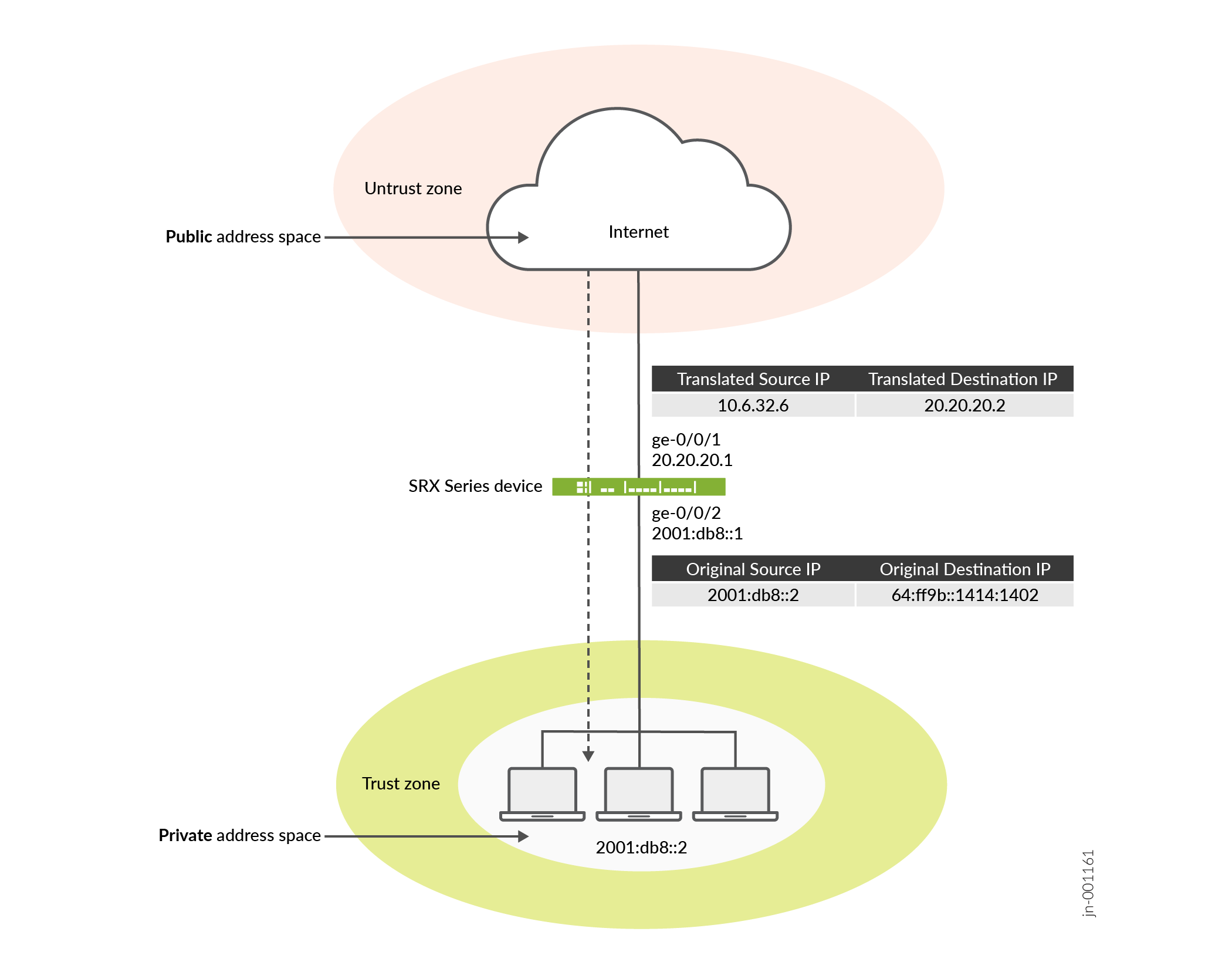
In this Static NAT64 topology, an IPv6-only client communicates with an IPv4 server through the SRX Series Firewall. The firewall translates IPv6 addresses to IPv4 using Static NAT64 mappings, while a DNS64 server synthesizes IPv6 DNS responses for seamless address resolution. This setup ensures smooth communication between IPv6-only clients and IPv4 servers without requiring dual-stack configurations.
|
Topology Components |
Role |
Function |
|---|---|---|
|
Client |
IPv6-only device |
Initiates requests from an IPv6-only environment to communicate with IPv4 servers. |
|
SRX Series Firewall |
NAT64 gateway |
Translates IPv6 addresses to IPv4 addresses using the configured Static NAT64 mapping, ensuring seamless communication across IP versions. |
|
DNS64 server |
DNS translator |
Converts IPv4 DNS responses for the client, enabling address resolution. |
|
IPv4 server |
Destination server |
Responds to client requests using its IPv4 address, allowing interaction with IPv6-only clients through NAT64. |
Topology Illustration
Configure Static NAT64 on Device-Under-Test (DUT)
For complete sample configurations on the DUT, see:
Verification
Verify Static NAT64 Configuration
Purpose
Verify that there is traffic matching the static NAT64 rule set.
Action
From operational mode, enter the show security nat static
rule command. View the Translation hits field to check for
traffic that matches the rule.
Meaning
Appendix 1: Set Commands on All Devices
The following example requires navigating through various levels of the Junos OS configuration hierarchy. For detailed guidance on navigating the CLI, see Use the CLI Editor in Configuration Mode.
set security nat source pool p1 address 10.6.32.0/24 set security nat source rule-set src_rs1 from zone trust set security nat source rule-set src_rs1 to zone untrust set security nat source rule-set src_rs1 rule source_rule match source-address 2001:db8::/96 set security nat source rule-set src_rs1 rule source_rule match destination-address 0.0.0.0/0 set security nat source rule-set src_rs1 rule source_rule then source-nat pool p1 set security nat static rule-set static_rs1 from zone trust set security nat static rule-set static_rs1 rule static_rule match destination-address 64:ff9b::/96 set security nat static rule-set static_rs1 rule static_rule then static-nat inet set security nat proxy-arp interface ge-0/0/2.0 address 10.6.32.1/32 to 10.6.32.249/32 set security policies from-zone trust to-zone untrust policy p1 match source-address any set security policies from-zone trust to-zone untrust policy p1 match destination-address any set security policies from-zone trust to-zone untrust policy p1 match application any set security policies from-zone trust to-zone untrust policy p1 then permit set security zones security-zone trust host-inbound-traffic system-services all set security zones security-zone trust host-inbound-traffic protocols all set security zones security-zone trust interfaces ge-0/0/2.0 set security zones security-zone untrust host-inbound-traffic system-services all set security zones security-zone untrust host-inbound-traffic protocols all set security zones security-zone untrust interfaces ge-0/0/1.0 set interfaces ge-0/0/1 unit 0 family inet address 20.20.20.1/24 set interfaces ge-0/0/2 unit 0 family inet6 address 2001:db8::1/96
Appendix 2: Show Configuration Output on DUT
Show command output on the DUT.
From operational mode, verify your configuration using the following commands. If the output
user@host# show interfaces
ge-0/0/1 {
unit 0 {
family inet {
address 20.20.20.1/24;
}
}
}
ge-0/0/2 {
unit 0 {
family inet6 {
address 2001:db8::1/96;
}
}
}user@host# show security zones
security-zone trust {
host-inbound-traffic {
system-services {
all;
}
protocols {
all;
}
}
interfaces {
ge-0/0/2.0;
}
}
security-zone untrust {
host-inbound-traffic {
system-services {
all;
}
protocols {
all;
}
}
interfaces {
ge-0/0/1.0;
}
}user@host# show security policies
from-zone trust to-zone untrust {
policy p1 {
match {
source-address any;
destination-address any;
application any;
}
then {
permit;
}
}
}user@host# show security nat
source {
pool p1 {
address {
10.6.32.0/24;
}
}
rule-set src_rs1 {
from zone trust;
to zone untrust;
rule source_rule {
match {
source-address 2001:db8::/96;
destination-address 0.0.0.0/0;
}
then {
source-nat {
pool {
p1;
}
}
}
}
}
}
static {
rule-set static_rs1 {
from zone trust;
rule static_rule {
match {
destination-address 64:ff9b::/96;
}
then {
static-nat {
inet;
}
}
}
}
}
proxy-arp {
interface ge-0/0/2.0 {
address {
10.6.32.1/32 to 10.6.32.249/32;
}
}
}Example: Configuring Static NAT for Port Mapping
This example describes how to configure static NAT mappings of a public address to private addresses on a specified range of ports.
This topic includes the following sections:
Requirements
Before you begin:
Configure network interfaces on the device. See Interfaces User Guide for Security Devices.
Create security zones and assign interfaces to them. See Understanding Security Zones.
Overview
This example uses the trust security zone for the private address space and the untrust security zone for the public address space.
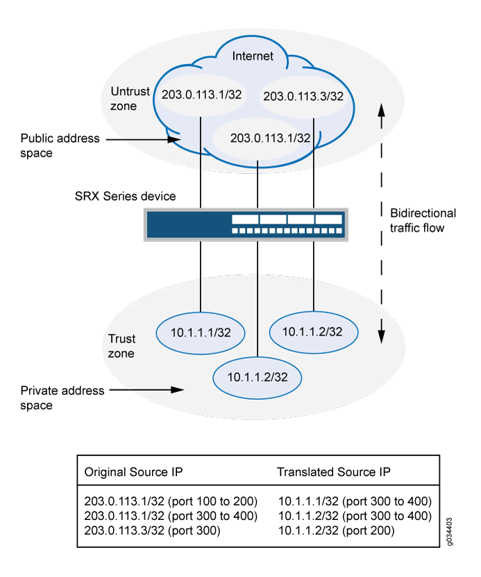
In Figure 4, devices in the untrust zone access a server in the trust zone by way of public addresses 203.0.113.1/32, 203.0.113.1/32, and 203.0.113.3/32. For packets that enter the Juniper Networks security device from the untrust zone with the destination IP addresses 203.0.113.1/32, 203.0.113.1/32, and 203.0.113.3/32, the destination IP address is translated to the private addresses 10.1.1.1/32,10.1.1.2/32, and 10.1.1.2/32.
-
To configure the destination port, you must use an IP address for the destination address field instead of an IP address prefix.
-
You must configure the destination port to configure the mapped port and vice versa.
-
Use the same number range for the ports while configuring the destination port and the mapped port.
-
If you do not configure the destination port and the mapped port, the IP mapping will be the one-to-one mapping.
-
Any address overlapping or any address and port overlapping is not allowed.
This example describes the following configurations:
Static NAT rule set rs1 with rule r1 to match packets from the untrust zone with the destination address 203.0.113.1/32 and destination port 100 to 200. For matching packets, the destination IP address is translated to the private address 10.1.1.1/32 and mapped to port 300 to 400.
Static NAT rule set rs1 with rule r2 to match packets from the untrust zone with the destination address 203.0.113.1/32 and destination port 300 to 400. For matching packets, the destination IP address is translated to the private address 10.1.1.2/32 and mapped to port 300 to 400.
Static NAT rule set rs1 with rule r3 to match packets from the untrust zone with the destination address 203.0.113.3/32 and destination port 300. For matching packets, the destination IP address is translated to the private address 10.1.1.2/32 and mapped to port 200.
Configuration
CLI Quick Configuration
To quickly configure this example, copy the following commands, paste them into a text file, remove any line breaks, change any details necessary to match your network configuration, copy and paste the commands into the CLI at the [edit] hierarchy level, and then enter commit from configuration mode.
set security nat static rule-set rs from zone untrustset security nat static rule-set rs rule r1 match destination-address 203.0.113.1/32set security nat static rule-set rs rule r1 match destination-port 100 to 200set security nat static rule-set rs rule r1 then static-nat prefix 10.1.1.1/32set security nat static rule-set rs rule r1 then static-nat prefix mapped-port 300 to 400set security nat static rule-set rs rule r2 match destination-address 203.0.113.1/32set security nat static rule-set rs rule r2 match destination-port 300 to 400set security nat static rule-set rs rule r2 then static-nat prefix 10.1.1.2/32set security nat static rule-set rs rule r2 then static-nat prefix mapped-port 300 to 400set security nat static rule-set rs rule r3 match destination-address 203.0.113.3/32set security nat static rule-set rs rule r3 match destination-port 300set security nat static rule-set rs rule r3 then static-nat prefix 10.1.1.2/32set security nat static rule-set rs rule r3 then static-nat prefix mapped-port 200
Procedure
Step-by-Step Procedure
The following example requires you to navigate throughout various levels in the configuration hierarchy. For instructions on how to do that, see Using the CLI Editor in Configuration Mode.
To configure a static NAT mapping from a private subnet address to a public subnet address:
Create a static NAT rule set.
[edit security nat static]user@host# set rule-set rs from zone untrustConfigure a rule that matches packets and translates the destination address in the packets to a private address.
[edit security nat static]user@host# set rule-set rs rule r1 match destination-address 203.0.113.1/32user@host# set rule-set rs rule r1 match destination-port 100 to 200user@host# set rule-set rs rule r1 then static-nat prefix 10.1.1.1/32user@host# set rule-set rs rule r1 then static-nat prefix mapped-port 300 to 400Configure a rule that matches packets and translates the destination address in the packets to a private address.
[edit security nat static]user@host# set rule-set rs rule r2 match destination-address 203.0.113.1/32user@host# set rule-set rs rule r2 match destination-port 300 to 400user@host# set rule-set rs rule r2 then static-nat prefix 10.1.1.2/32user@host# set rule-set rs rule r2 then static-nat prefix mapped-port 300 to 400Configure a rule that matches packets and translates the destination address in the packets to a private address.
[edit security nat static]user@host# set rule-set rs rule r3 match destination-address 203.0.113.3/32user@host# set rule-set rs rule r3 match destination-port 300user@host# set rule-set rs rule r3 then static-nat prefix 10.1.1.2/32user@host# set rule-set rs rule r3 then static-nat prefix mapped-port 200
Results
From configuration mode, confirm your configuration by entering the show security nat command. If the output does not display the intended configuration, repeat the configuration instructions in this example to correct it.
[edit]
user@host# show security nat
security {
nat {
static {
rule-set rs {
from zone untrust;
rule r1 {
match {
destination-address 203.0.113.1/32;
destination-port 100 to 200;
}
then {
static-nat {
prefix {
10.1.1.1/32;
mapped-port 300 to 400;
}
}
}
}
rule r2 {
match {
destination-address 203.0.113.1/32;
destination-port 300 to 400;
}
then {
static-nat {
prefix {
10.1.1.2/32;
mapped-port 300 to 400;
}
}
}
}
rule r3 {
match {
destination-address 203.0.113.3/32;
destination-port 300;
}
then {
static-nat {
prefix {
10.1.1.2/32;
mapped-port 200;
}
}
}
}
}
}
}
}
If you are done configuring the device, enter commit from configuration mode.
Verification
Verifying Static NAT Configuration
Purpose
Verify that there is traffic matching the static NAT rule set.
Action
From operational mode, enter the show security nat static rule command. View the Translation hits field to check for traffic that matches the rule.
user@host> show security nat static rule all
Total static-nat rules: 3
Static NAT rule: r2 Rule-set: rs
Rule-Id : 3
Rule position : 2
From zone : untrust
Destination addresses : 203.0.113.1
Destination ports : 300 - 400
Host addresses : 10.1.1.2
Host ports : 300 - 400
Netmask : 32
Host routing-instance : N/A
Translation hits : 0
Static NAT rule: r3 Rule-set: rs
Rule-Id : 4
Rule position : 3
From zone : untrust
Destination addresses : 203.0.113.3
Destination ports : 300 - 300
Host addresses : 10.1.1.2
Host ports : 200 - 200
Netmask : 32
Host routing-instance : N/A
Translation hits : 0
Static NAT rule: r1 Rule-set: rs
Rule-Id : 9
Rule position : 1
From zone : untrust
Destination addresses : 203.0.113.1
Destination ports : 100 - 200
Host addresses : 10.1.1.1
Host ports : 300 - 400
Netmask : 32
Host routing-instance : N/A
Translation hits : 0
Troubleshooting
Troubleshooting Static NAT Port Configuration
Problem
Static NAT port mapping configuration failures occur during a commit.
Invalid configurations with overlapped IP addresses and ports result in commit failure.
The following example shows invalid configurations with overlapped addresses and ports:
set security nat static rule-set rs rule r1 match destination-address 203.0.113.1set security nat static rule-set rs rule r1 then static-nat prefix 10.1.1.1set security nat static rule-set rs rule r2 match destination-address 203.0.113.1set security nat static rule-set rs rule r2 match destination-port 300 to 400set security nat static rule-set rs rule r2 then static-nat prefix 10.1.1.2set security nat static rule-set rs rule r2 then static-nat prefix mapped-port 300 to 400set security nat static rule-set rs rule r1 match destination-address 203.0.113.1set security nat static rule-set rs rule r1 match destination-port 100 to 200set security nat static rule-set rs rule r1 then static-nat prefix 10.1.1.1set security nat static rule-set rs rule r1 then static-nat prefix mapped-port 300 to 400set security nat static rule-set rs rule r2 match destination-address 203.0.113.2set security nat static rule-set rs rule r2 match destination-port 300 to 400set security nat static rule-set rs rule r2 then static-nat prefix 10.1.1.1set security nat static rule-set rs rule r2 then static-nat prefix mapped-port 390 to 490
The following error message was displayed when the aforementioned configuration was submitted for commit:
error: 'prefix/mapped-port' of static nat rule r2 overlaps with 'prefix/mapped-port' of static nat rule r1 error: configuration check-out failed
Solution
To configure the destination port, you must avoid any address overlapping or any address and port overlapping. For an example of valid configuration, see Configuration
Configure Static NAT and PAT for QFX5120
For destination NAT and destination NAT PAT:
-
Enable proxy ARP on public interfaces if the translated public IP address is in same subnet as address assigned to the public interface.
-
Add a static route for the translated public IP address with next hop as local private IP address.
Monitoring Static NAT Information
Purpose
View static NAT rule information.
Action
Select Monitor>NAT>Static NAT in the J-Web user interface, or enter the following CLI command:
show security
nat static rule
Table 3 summarizes key output fields in the static NAT display.
Field |
Values |
Action |
|---|---|---|
Rule-set Name |
Name of the rule set. |
Select all rule sets or a specific rule set to display from the list. |
Total rules |
Number of rules configured. |
– |
ID |
Rule ID number. |
– |
Position |
Position of the rule that indicates the order in which it applies to traffic. |
– |
Name |
Name of the rule. |
– |
Ruleset Name |
Name of the rule set. |
– |
From |
Name of the routing instance/interface/zone from which the packet comes |
– |
Source addresses |
Source IP addresses. |
– |
Source ports |
Source port numbers. |
– |
Destination addresses |
Destination IP address and subnet mask. |
– |
Destination ports |
Destination port numbers . |
– |
Host addresses |
Name of the host addresses. |
– |
Host ports |
Host port numbers. |
|
Netmask |
Subnet IP address. |
– |
Host routing instance |
Name of the routing instance from which the packet comes. |
– |
Alarm threshold |
Utilization alarm threshold. |
– |
Sessions (Succ/Failed/Current) |
Successful, failed, and current sessions.
|
– |
Translation hits |
Number of times a translation in the translation table is used for a static NAT rule. |
– |
Top 10 Translation Hits Graph |
Displays the graph of top 10 translation hits. |
– |