Understanding Multitopology Routing in Conjunction with PIM
Protocol Independent Multicast (PIM), in conjunction with multitopology routing extensions to OSPF (multitopology OSPF) and BGP, can direct multicast traffic over particular paths based on traffic characteristics.
Junos OS provides a mechanism whereby multicast traffic traverses user-specified topology paths based on the sender’s source address. Multitopology routing (MTR) is used for OSPF, BGP, and route resolution over the specified topology routing tables. OSPF and BGP independently populate the routing table used by PIM. Firewall filters are not required because the multicast forwarding plane uses the multicast tree after it has been built.
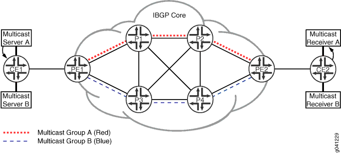
Figure 1 shows a diagram of routing topology paths, where the dashed lines are associated with multicast group A (topology red), and the dotted lines are associated with multicastgroup B (topology blue).

Two copies of the same stream enter Device PE1 and then traverse separate paths over the internal BGP (IBGP) core.
This solution leverages Junos OS features that allow particular routing tables to perform route resolution using specified routing tables.
The configuration includes a combination of the following features:
-
BGP communities
-
Separate IBGP next hops belonging to user-specified OSPF routing topologies
-
Route resolution over user-specified topology routing tables
-
A separate routing table (inet.2) for multicast protocols
Commonly, networks use a separate routing table for multicast. In Junos OS, the multicast routing table is inet.2. Routing topologies are grouped based on BGP communities. Each group represents a set of IP addresses associated with multicast servers and receivers. Primarily, the group must be related to the set of servers because the multicast receivers initiate tree creation toward these servers. Multicast traffic directed downstream toward receivers uses the previously created PIM tree, and therefore the forwarding plane does not need to know about routing topologies.
PIM uses the inet.2 routing table for lookups of multicast source addresses. These IP addresses used for tree creation are IP unicast addresses. The customer edge (CE) routers, nearest to the multicast servers, announce the multicast source IP addresses to the provider edge (PE) routers using external BGP (EBGP). They are announced with both family inet unicast and family inet multicast, thus causing the BGP route to be added to the default routing table inet.0 and to inet.2.
Both versions of the route are injected by the PE router into IBGP. Each BGP route injected into IBGP has a specific protocol next hop. Junos OS provides the flexibility to set the protocol next hop when exporting the route into IBGP. For instance, a next-hop self can be set with an export policy configuration. You can also set the protocol next hop to a route associated with a specified topology routing table.
Keeping in mind that an EBGP route can have a community associated with a routing topology, you can conveniently configure a policy to use this community to designate which protocol next hop should be set when exporting the IBGP route into inet.2. As such, a specific protocol next-hop IP address is required for each topology on each router injecting IBGP routes. You can configure multiple secondary loopback IP addresses on a router to be used as protocol next-hop addresses.
A group of BGP routes associated with a routing topology use the same unique protocol next hop. For instance, if you configure a PE router to handle two routing topologies, you would also configure two unique nonprimary addresses under loopback interface lo0. Next, associate each nonprimary loopback IP address with a topology for inclusion in the associated topology routing table. Configure the loopback IP address and topology under an OSPF interface statement. You must specifically disable all other topologies known to OSPF for two reasons. First, the loopback address specific to a topology must reside in only one topology routing table. Second, once the topology is added to OSPF, the topology defaults to being enabled on all subsequent interfaces under OSPF.
You can specify up to two routing tables in the resolution configuration. A key element to this solution is that the protocol next-hop address resides in only one topology table. That is, the protocol next hop belongs to a remote PE secondary loopback address and is injected into only one topology table. The route resolution scheme first checks the topology table for the protocol next-hop address. If the address is found, it uses this entry. If it is not found, the resolution scheme then checks the second topology table. Hence, only one topology table is used for each protocol nexthop address.
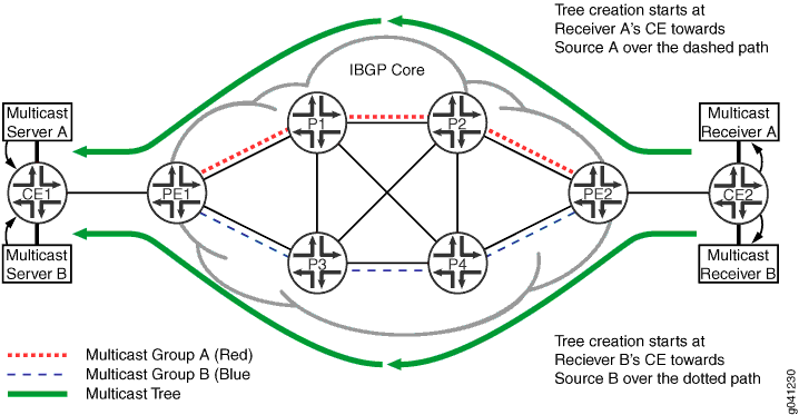
Links can support all routing topologies to provide a backup path should a primary multicast path fail. You can configure specific OSPF link metrics on topologies to identify paths and build trees to different servers. When a multicast tree gets built with PIM join messages directed toward the source, it follows the most preferred path. A multicast tree to a different multicast source (in a different routing topology) can create another tree along a different path.
Figure 2 shows an example of two trees using different paths over different topologies. It shows Server A using the multicast tree with the dashed line as its path and Server B using the multicast tree with the dotted line as its path.

