Example: Configuring Source-Specific Draft-Rosen 7 Multicast VPNs
Understanding Source-Specific Multicast VPNs
A draft-rosen MVPN with service provider tunnels operating in SSM mode uses BGP signaling for autodiscovery of the PE routers. These MVPNs are also referred to as Draft Rosen 7.
Each PE sends an MDT subsequent address family identifier (MDT-SAFI) BGP network layer reachability information (NLRI) advertisement. The advertisement contains the following information:
Route distinguisher
Unicast address of the PE router to which the source site is attached (usually the loopback)
Multicast group address
Route target extended community attribute
Each remote PE router imports the MDT-SAFI advertisements from each of the other PE routers if the route target matches. Each PE router then joins the (S,G) tree rooted at each of the other PE routers.
After a PE router discovers the other PE routers, the source and group are bound to the VPN routing and forwarding (VRF) through the multicast tunnel de-encapsulation interface.
A draft-rosen MVPN with service provider tunnels operating in any-source multicast sparse-mode uses a shared tree and rendezvous point (RP) for autodiscovery of the PE routers. The PE that is the source of the multicast group encapsulates multicast data packets into a PIM register message and sends them by means of unicast to the RP router. The RP then builds a shortest-path tree (SPT) toward the source PE. The remote PE that acts as a receiver for the MDT multicast group sends (*,G) join messages toward the RP and joins the distribution tree for that group.
Draft-Rosen 7 Multicast VPN Control Plane
The control plane of a draft-rosen MVPN with service provider tunnels operating in SSM mode must be configured to support autodiscovery.
After the PE routers are discovered, PIM is notified of the multicast source and group addresses. PIM binds the (S,G) state to the multicast tunnel (mt) interface and sends a join message for that group.
Autodiscovery for a draft-rosen MVPN with service provider tunnels operating in SSM mode uses some of the facilities of the BGP-based MVPN control plane software module. Therefore, the BGP-based MVPN control plane must be enabled. The BGP-based MVPN control plane can be enabled for autodiscovery only.
Example: Configuring Source-Specific Multicast for Draft-Rosen Multicast VPNs
This example shows how to configure a draft-rosen Layer 3 VPN operating in source-specific multicast (SSM) mode. This example is based on the Junos OS implementation of the IETF Internet draft draft-rosen-vpn-mcast-07.txt, Multicast in MPLS/BGP VPNs.
Requirements
This example uses the following hardware and software components:
-
Junos OS Release 9.4 or later
-
Make sure that the routing devices support multicast tunnel (mt) interfaces.
A tunnel-capable PIC supports a maximum of 512 multicast tunnel interfaces. Both default and data MDTs contribute to this total. The default MDT uses two multicast tunnel interfaces (one for encapsulation and one for de-encapsulation). To enable an M Series or T Series router to support more than 512 multicast tunnel interfaces, another tunnel-capable PIC is required. See Tunnel Services PICs and Multicast and Load Balancing Multicast Tunnel Interfaces Among Available PICs.
In Junos OS Release 17.3R1, the pim-ssm
hierarchy was moved from provider-tunnel to
the provider-tunnel family inet and
provider-tunnel family inet6
hierarchies as part of an upgrade to add IPv6 support for
default MDT in Rosen 7, and data MDT for Rosen 6 and Rosen
7.
Overview
The IETF Internet draft draft-rosen-vpn-mcast-07.txt introduced the ability to configure the provider network to operate in SSM mode. When a draft-rosen multicast VPN is used over an SSM provider core, there are no PIM RPs to provide rendezvous and autodiscovery between PE routers. Therefore, draft-rosen-vpn-mcast-07 specifies the use of a BGP network layer reachability information (NLRI), called MDT subaddress family identifier information (MDT-SAFI) to facilitate autodiscovery of PEs by other PEs. MDT-SAFI updates are BGP messages distributed between intra-AS internal BGP peer PEs. Thus, receipt of an MDT-SAFI update enables a PE to autodiscover the identity of other PEs with sites for a given VPN and the default MDT (S,G) routes to join for each. Autodiscovery provides the next-hop address of each PE, and the VPN group address for the tunnel rooted at that PE for the given route distinguisher (RD) and route-target extended community attribute.
This example includes the following configuration options to enable draft-rosen SSM:
-
protocols bgp group group-name family inet-mdt signaling—Enables MDT-SAFI signaling in BGP.
-
routing-instance instance-name protocols mvpn family inet autodiscovery-only intra-as inclusive—Enables the multicast VPN to use the MDT-SAFI autodiscovery NLRI.
-
routing-instance instance-name protocols pim mvpn—Specifies the SSM control plane. When pim mvpn is configured for a VRF, the VPN group address must be specified with the
provider-tunnel pim-ssm
                                                  group-address
statement. -
routing-instance instance-name protocols pim mvpn family inet autodiscovery inet-mdt—Enables PIM to learn about neighbors from the MDT-SAFI autodiscovery NLRI.
-
routing-instance instance-name provider-tunnel family inet pim-ssm group-address multicast-address—Configures the provider tunnel that serves as the control plane and enables the provider tunnel to have a static group address. Unlike draft-rosen multicast VPNs with ASM provider cores, the SSM configuration does not require that each PE for a VPN use the same group address. This is because the rendezvous point assignment and autodiscovery are not accomplished over the default MDT tunnels for the group. Thus, you can configure some or all PEs in a VPN to use a different group, but the same group cannot be used in different VPNs on the same PE router.
-
routing-instances ce1 vrf-target target:100:1—Configures the VRF export policy. When you configure draft-rosen multicast VPNs with provider tunnels operating in source-specific mode and using the
vrf-targetstatement, the VRF export policy is automatically generated and automatically accepts routes from the vrf-name.mdt.0 routing table.Note:When you configure draft-rosen multicast VPNs with provider tunnels operating in source-specific mode and using the
vrf-exportstatement to specify the export policy, the policy must have a term that accepts routes from the vrf-name.mdt.0 routing table. This term ensures proper PE autodiscovery using the inet-mdt address family.
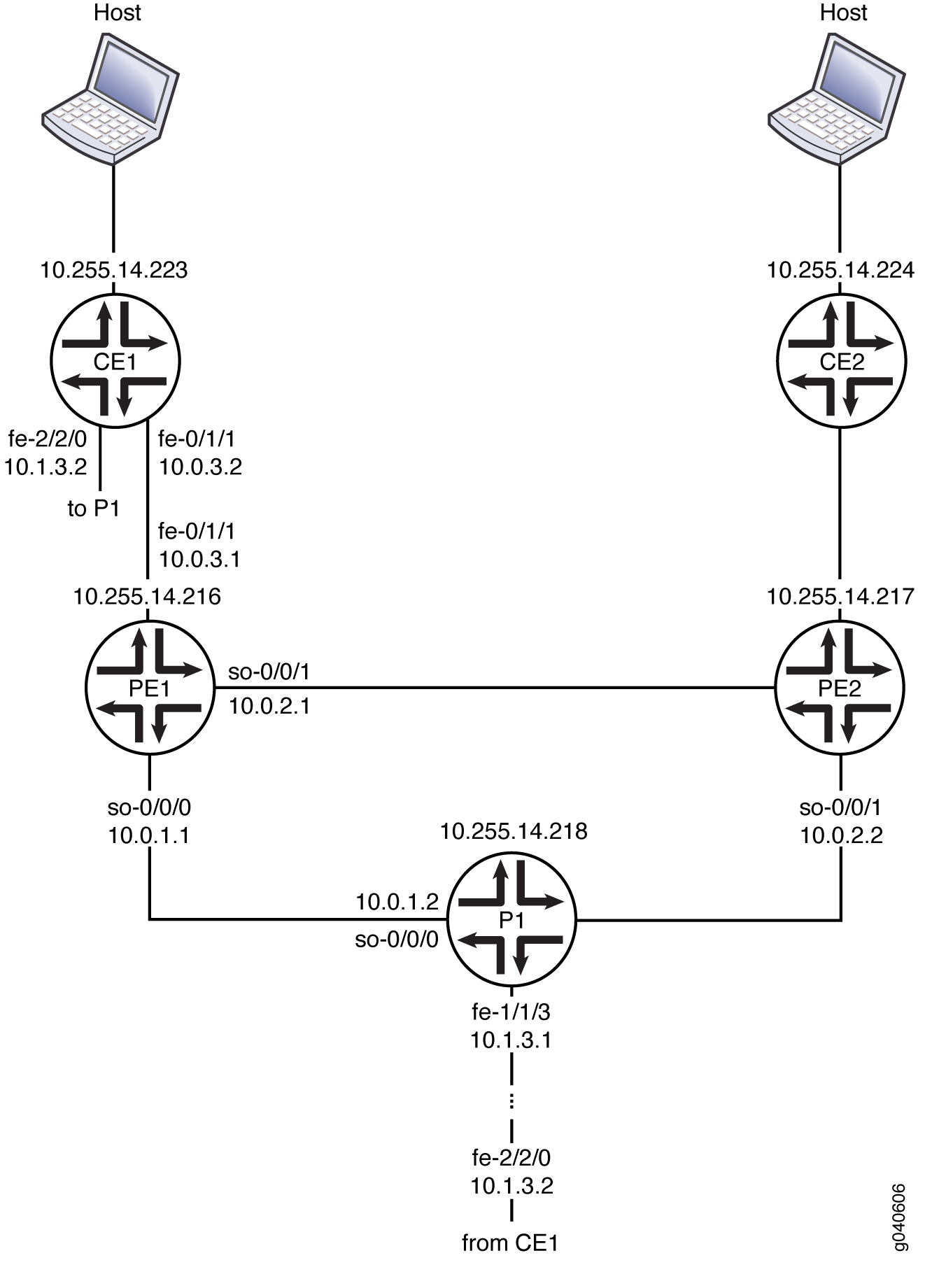
Topology
Figure 1 shows the topology for this example.
Configuration
- Procedure
- Interface Configuration
- Multicast Group Management
- MPLS Signaling Protocol and MPLS LSPs
- BGP
- Interior Gateway Protocol
- PIM
- Routing Instance
Procedure
CLI Quick Configuration
To quickly configure this example, copy the following
commands, paste them into a text file, remove any
line breaks, change any details necessary to match
your network configuration, and then copy and paste
the commands into the CLI at the
[edit] hierarchy level.
set interfaces so-0/0/0 description "TO P1_P1"
set interfaces so-0/0/0 unit 0 description "to P1 (provider router) so-0/0/0.0"
set interfaces so-0/0/0 unit 0 family inet address 10.0.1.1/30
set interfaces so-0/0/0 unit 0 family iso
set interfaces so-0/0/0 unit 0 family mpls
set interfaces so-0/0/1 description "TO PE2"
set interfaces so-0/0/1 unit 0 description "to PE2 (PE router) so-0/0/1.0"
set interfaces so-0/0/1 unit 0 family inet address 10.0.2.1/30
set interfaces so-0/0/1 unit 0 family iso
set interfaces so-0/0/1 unit 0 family mpls
set interfaces fe-0/1/1 description "TO CE1"
set interfaces fe-0/1/1 unit 0 description "to CE router fe-0/1/1.0"
set interfaces fe-0/1/1 unit 0 family inet address 10.0.3.1/30
set interfaces lo0 unit 0 description "PE1 (this PE router) Loopback"
set interfaces lo0 unit 1 family inet address 10.1.1.0/32
set routing-options autonomous-system 65200
set protocols igmp query-interval 2
set protocols igmp query-response-interval 1
set protocols igmp query-last-member-interval 1
set protocols igmp interface all immediate-leave
set protocols igmp interface fxp0.0 disable
set protocols rsvp interface all
set protocols rsvp interface so-0/0/0.0
set protocols rsvp interface so-0/0/1.0
set protocols mpls label-switched-path PE1-to-PE2 to 10.255.14.217
set protocols mpls label-switched-path PE1-to-PE2 primary PE1_PE2_prime
set protocols mpls label-switched-path PE1-to-P1 to 10.255.14.218
set protocols mpls label-switched-path PE1-to-P1 primary PE1_P1_prime
set protocols mpls path PE1_P1_prime 10.0.1.2
set protocols mpls path PE1_PE2_prime 10.0.2.2
set protocols mpls interface all
set protocols mpls interface fxp0.0 disable
set protocols bgp group int type internal
set protocols bgp group int local-address 10.255.14.216
set protocols bgp group int family inet unicast
set protocols bgp group int family inet-vpn unicast
set protocols bgp group int family inet-vpn multicast
set protocols bgp group int family inet-mdt signaling
set protocols bgp group int neighbor 10.255.14.218
set protocols bgp group int neighbor 10.255.14.217
set protocols ospf traffic-engineering
set protocols ospf area 0.0.0.0 interface lo0.0 passive
set protocols ospf area 0.0.0.0 interface so-0/0/0.0 metric 10
set protocols ospf area 0.0.0.0 interface so-0/0/1.0 metric 10
set protocols pim assert-timeout 5
set protocols pim join-prune-timeout 210
set protocols pim rp bootstrap-priority 10
set protocols pim rp local address 10.255.14.216
set protocols pim interface lo0.0
set protocols pim interface all hello-interval 1
set protocols pim interface fxp0.0 disable
set policy-options policy-statement bgp_ospf term 1 from protocol bgp
set policy-options policy-statement bgp_ospf term 1 then accept
set routing-instances ce1 instance-type vrf
set routing-instances ce1 interface fe-0/1/1.0
set routing-instances ce1 interface lo0.1
set routing-instances ce1 route-distinguisher 10:0
set routing-instances ce1 provider-tunnel pim-ssm group-address 232.1.1.1
set routing-instances ce1 vrf-target target:100:1
set routing-instances ce1 protocols ospf export bgp_ospf
set routing-instances ce1 protocols ospf sham-link local 01.1.1.0
set routing-instances ce1 protocols ospf area 0.0.0.0 sham-link-remote 10.1.1.1
set routing-instances ce1 protocols ospf area 0.0.0.0 sham-link-remote 10.1.1.2
set routing-instances ce1 protocols ospf area 0.0.0.0 interface lo0.1
set routing-instances ce1 protocols ospf area 0.0.0.0 interface fe-0/1/1.0 metric 10
set routing-instances ce1 protocols pim mvpn family inet autodiscovery inet-mdt
set routing-instances ce1 protocols pim interface lo0.1
set routing-instances ce1 protocols pim interface fe-0/1/1.0 priority 100
set routing-instances ce1 protocols pim interface fe-0/1/1.0 hello-interval 1
set routing-instances ce1 protocols mvpn family inet autodiscovery-only intra-as inclusive
Interface Configuration
Step-by-Step Procedure
The following example requires you to navigate various levels in the configuration hierarchy. For information about navigating the CLI, see Using the CLI Editor in Configuration Mode in the Junos OS CLI User Guide.
To configure the interfaces on one PE router:
-
Configure PE1’s interface to the provider router.
[edit interfaces so-0/0/0]
user@host# set description "TO P1"
user@host# set unit 0 description "to P1 (provider router, 10.255.14.218 ) so-0/0/0.0"
user@host# set unit 0 family inet address 10.0.1.1/30
user@host# set unit 0 family iso
user@host# set unit 0 family mpls
-
Configure PE1’s interface to PE2.
[edit interfaces so-0/0/1]
user@host# set description "TO PE2"
user@host# set unit 0 description "to PE2 (10.255.14.217) so-0/0/1.0"
user@host# set unit 0 family inet address 10.0.2.1/30
user@host# set unit 0 family iso
user@host# set unit 0 family mpls
-
Configure PE1’s interface to CE1.
[edit interfaces fe-0/1/1]
user@host# set description "TO CE1"
user@host# set unit 0 description "to CE1 (10.255.14.223) fe-0/1/1.0"
user@host# set unit 0 family inet address 10.0.3.1/30
user@host# set unit 0 family iso
user@host# set unit 0 family mpls
-
Configure PE1’s loopback interface.
[edit interfaces lo0]
user@host# set unit 0 description "PE1 (this PE router, 10.255.14.216) Loopback"
user@host# set unit 1 family inet address 10.1.1.0/32
Multicast Group Management
Step-by-Step Procedure
To configure multicast group management:
-
Configure the IGMP interfaces.
[edit protocols igmp]
user@host# set interface all immediate-leave
user@host# set interface fxp0.0 disable
-
Configure the IGMP settings.
[edit protocols igmp]
user@host# set query-interval 2
user@host# set query-response-interval 1
user@host# set query-last-member-interval 1
MPLS Signaling Protocol and MPLS LSPs
Step-by-Step Procedure
To configure the MPLS signaling protocol and MPLS LSPs:
-
Configure RSVP signaling among this PE router (PE1), the other PE router (PE2). and the provider router (P1).
[edit protocols rsvp]
user@host# set interface so-0/0/0.0
user@host# set interface so-0/0/1.0
-
Configure MPLS LSPs.
[edit protocols mpls]
user@host# set label-switched-path pe1-to-pe2 to 10.255.14.217
user@host# set label-switched-path pe1-to-pe2 primary pe1_pe2_prime
user@host# set label-switched-path pe1-to-p1 to 10.255.14.218
user@host# set label-switched-path pe1-to-p1 primary pe1_p1_prime
user@host# set path pe1_p1_prime 10.0.1.2
user@host# set path pe1_pe2_prime 10.0.2.2
user@host# set interface all
user@host# set interface fxp0.0 disable
BGP
Step-by-Step Procedure
To configure BGP:
-
Configure the AS number. In this example, both of the PE routers and the provider router are in AS 65200.
[edit]
user@host# set routing-options autonomous-system 65200
-
Configure the internal BGP full mesh with the PE2 and P1 routers.
[edit protocols bgp group int]
user@host# set type internal
user@host# set local-address 10.255.14.216
user@host# set family inet unicast
user@host# set neighbor 10.255.14.218
user@host# set neighbor 10.255.14.217
-
Enable MDT-SAFI NLRI control plane messages.
[edit protocols bgp group int]
user@host# set family inet-mdt signaling
-
Enable BGP to carry Layer 3 VPN NLRI for the IPv4 address family.
[edit protocols bgp group int]
user@host# set family inet-vpn unicast
user@host# set family inet-vpn multicast
-
Configure BGP export policy.
[edit policy-options]
user@host# set policy-statement bgp_ospf term 1 from protocol bgp
user@host# set policy-statement bgp_ospf term 1 then accept
Interior Gateway Protocol
Step-by-Step Procedure
To configure the interior gateway protocol:
-
Configure the OSPF interfaces.
[edit protocols ospf]
user@host# set area 0.0.0.0 interface lo0.0 passive
user@host# set area 0.0.0.0 interface so-0/0/0.0 metric 10
user@host# set area 0.0.0.0 interface so-0/0/1.0 metric 10
-
Enable traffic engineering.
[edit protocols ospf]
user@host# set traffic-engineering
PIM
Step-by-Step Procedure
To configure PIM:
-
Configure timeout periods and the RP. Local RP configuration makes PE1 a statically defined RP.
[edit protocols pim]
user@host# set assert-timeout 5
user@host# set join-prune-timeout 210
user@host# set rp bootstrap-priority 10
user@host# set rp local address 10.255.14.216
-
Configure the PIM interfaces.
[edit protocols pim]
user@host# set interface lo0.0
user@host# set interface all hello-interval 1
user@host# set interface fxp0.0 disable
Routing Instance
Step-by-Step Procedure
To configure the routing instance between PE1 and CE1:
-
Configure the basic routing instance.
[edit routing-instances ce1]
user@host# set instance-type vrf
user@host# set interface fe-0/1/1.0
user@host# set interface lo0.1
user@host# set route-distinguisher 10:0
user@host# set vrf-target target:100:1
-
Configure the SSM provider tunnel.
[edit routing-instances ce1]
user@host# set provider-tunnel family inet pim-ssm group-address (Routing Instances) 232.1.1.1
-
Configure OSPF in the routing instance.
[edit routing-instances ce1 protocols ospf]
user@host# set export bgp_ospf
user@host# set sham-link local 10.1.1.0
user@host# set area 0.0.0.0 sham-link-remote 10.1.1.1
user@host# set area 0.0.0.0 sham-link-remote 10.1.1.2
user@host# set area 0.0.0.0 interface lo0.1
user@host# set area 0.0.0.0 interface fe-0/1/1.0 metric 10
-
Configure PIM in the routing instance.
[edit routing-instances ce1 protocols pim]
user@host# set interface lo0.1
user@host# set interface fe-0/1/1.0 priority 100
user@host# set interface fe-0/1/1.0 hello-interval 1
-
Configure draft-rosen VPN autodiscovery for provider tunnels operating in SSM mode.
[edit routing-instances ce1 protocols pim ]
user@host# set mvpn family inet autodiscovery inet-mdt
-
Configure the BGP-based MVPN control plane to provide signaling only for autodiscovery and not for PIM operations.
[edit routing-instances ce1 protocols mvpn family inet]
user@host# set autodiscovery-only intra-as inclusive
Verification
You can monitor the operation of the routing instance by running the
show route table ce1.mdt.0 command.
You can manage the group-instance mapping for local SSM tunnel roots by
running the show pim mvpn command.
The show pim mdt command shows the tunnel type and
source PE address for each outgoing and incoming MDT. In addition,
because each PE might have its own default MDT group address, one
incoming entry is shown for each remote PE. Outgoing data MDTs are
shown after the outgoing default MDT. Incoming data MDTs are shown
after all incoming default MDTS.
For troubleshooting, you can configure tracing operations for all of the protocols.