ON THIS PAGE
Example: Configuring Multicast VLAN Registration on EX Series Switches Without ELS
Multicast VLAN registration (MVR) enables hosts that are not part of a multicast VLAN (MVLAN) to receive multicast streams from the MVLAN, which enable the MVLAN to be shared across the Layer 2 network and eliminate the need to send duplicate multicast streams to each requesting VLAN in the network. Hosts remain in their own VLANs for bandwidth and security reasons.
This example describes configuring MVR only on Junos switching devices that do not support the Enhanced Layer 2 Software configuration style.
Requirements
This example uses the following hardware and software components:
One Junos switching device.
Before you configure MVR, be sure you have:
Configured two or more VLANs on the switch. See the task for your platform:
Connected the switch to a network that can transmit IPTV multicast streams from a video server.
Connected a host that is capable of receiving IPTV multicast streams to an interface in one of the VLANs.
Overview and Topology
In a standard Layer 2 network, a multicast stream received on one VLAN is never distributed to interfaces outside that VLAN. If hosts in multiple VLANs request the same multicast stream, a separate copy of that multicast stream is distributed to the requesting VLANs.
MVR introduces the concept of a multicast source VLAN (MVLAN), which is created by MVR and becomes the only VLAN over which multicast traffic flows throughout the Layer 2 network. Multicast traffic can then be selectively forwarded from interfaces on the MVLAN (source ports) to hosts that are connected to interfaces (multicast receiver ports) that are not part of the multicast source VLAN. When you configure an MVLAN, you assign a range of multicast group addresses to it. You then configure other VLANs to be MVR receiver VLANs, which receive multicast streams from the MVLAN. The MVR receiver ports comprise all the interfaces that exist on any of the MVR receiver VLANs.
Topology
You can configure MVR to operate in one of two modes: transparent mode (the default mode) or proxy mode. Both modes enable MVR to forward only one copy of a multicast stream to the Layer 2 network.
In transparent mode, the switch receives one copy of each IPTV multicast stream and then replicates the stream only to those hosts that want to receive it, while forwarding all other types of multicast traffic without modification. Figure 1 shows how MVR operates in transparent mode.
In proxy mode, the switch acts as a proxy for the IGMP multicast router in the MVLAN for MVR group memberships established in the MVR receiver VLANs and generates and sends IGMP packets into the MVLAN as needed. Figure 2 shows how MVR operates in proxy mode.
This example shows how to configure MVR in both transparent mode and proxy mode on a Junos switching device.. The topology includes a video server that is connected to a multicast router, which in turn forwards the IPTV multicast traffic in the MVLAN to the Layer 2 network.
Figure 1 shows the MVR topology in transparent mode. Interfaces P1 and P2 on Switch C belong to service VLAN s0 and MVLAN mv0. Interface P4 of Switch C also belongs to service VLAN s0. In the upstream direction of the network, only non-IPTV traffic is being carried in individual customer VLANs of service VLAN s0. VLAN c0 is an example of this type of customer VLAN. IPTV traffic is being carried on MVLAN mv0. If any host on any customer VLAN connected to port P4 requests an MVR stream, Switch C takes the stream from VLAN mv0 and replicates that stream onto port P4 with tag mv0. IPTV traffic, along with other network traffic, flows from port P4 out to the Digital Subscriber Line Access Multiplexer (DSLAM) D1.
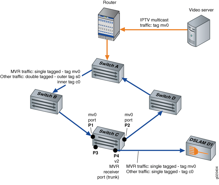
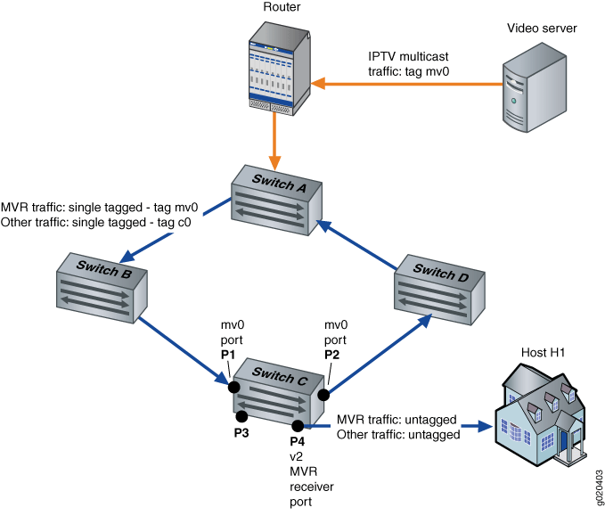
Figure 2 shows the MVR topology in proxy mode. Interfaces P1 and P2 on Switch C belong to MVLAN mv0 and customer VLAN c0. Interface P4 on Switch C is an access port of customer VLAN c0. In the upstream direction of the network, only non-IPTV traffic is being carried on customer VLAN c0. Any IPTV traffic requested by hosts on VLAN c0 is replicated untagged to port P4 based on streams received in MVLAN mv0. IPTV traffic flows from port P4 out to an IPTV-enabled device in Host H1. Other traffic, such as data and voice traffic, also flows from port P4 to other network devices in Host H1.
For information on VLAN tagging, see the topic for your platform:
Configuration
Procedure
CLI Quick Configuration
To quickly configure this example, copy the following commands, paste
them into a text file, remove any line breaks, change any details necessary to match your
network configuration, and then copy and paste the commands into the CLI at the [edit
protocols igmp-snooping] hierarchy level.
set vlan mv0 data-forwarding source groups 225.10.0.0/16 set vlan v2 data-forwarding receiver source-vlans mv0 set vlan v2 data-forwarding receiver install set vlan mv0 proxy source-address 10.1.1.1
Step-by-Step Procedure
The following example requires that you navigate various levels in the configuration hierarchy. For information about navigating the CLI, see Using the CLI Editor in Configuration Mode in the CLI User Guide.
To configure MVR:
Configure VLAN mv0 to be an MVLAN:
[edit protocols igmp-snooping] user@switch# set vlan mv0 data-forwarding source groups 225.10.0.0/16
Configure VLAN v2 to be a multicast receiver VLAN with mv0 as its source:
[edit protocols igmp-snooping]
user@switch# set vlan v2 data-forwarding receiver source-vlans mv0
(Optional) Install forwarding entries in the multicast receiver VLAN v2:
[edit protocols igmp-snooping]
user@switch# set vlan v2 data-forwarding receiver install
(Optional) Configure MVR in proxy mode:
[edit protocols igmp-snooping]
user@switch# set vlan mv0 proxy source-address 10.1.1.1
Results
From configuration mode, confirm your configuration by entering the show command at the [edit protocols igmp-snooping] hierarchy level. If the output
does not display the intended configuration, repeat the instructions in this example to correct
the configuration.
[edit protocols igmp-snooping]
user@switch# show
vlan mv0 {
    proxy {
        source-address 10.1.1.1;
    }
    data-forwarding {
        source {
            groups 225.10.0.0/16;
        }
    }
}
vlan v2 {
    data-forwarding {
        receiver {
            source-vlans mv0;
            install;
        }
    }
}