Junos Multi-Access User Plane Overview
Introduction
The 3rd Generation Partnership Project (3GPP) introduced the Evolved Packet Core (EPC) for core network architecture. As Figure 1 shows, the four main EPC network elements are:
Serving Gateway
Packet Data Network (PDN) Gateway
Mobility Management Entity (MME)
Home Subscriber Server (HSS)
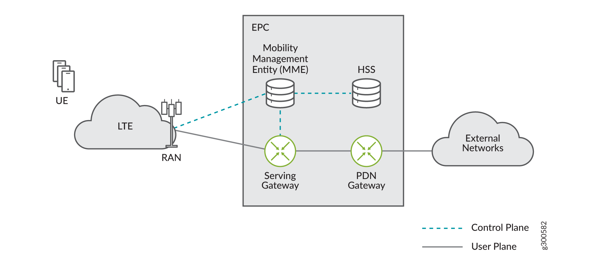
User Equipment (UE) has control path connectivity and data path connectivity to the EPC network elements over eNodeB base stations. The EPC provides data connectivity to external networks such as the Internet.
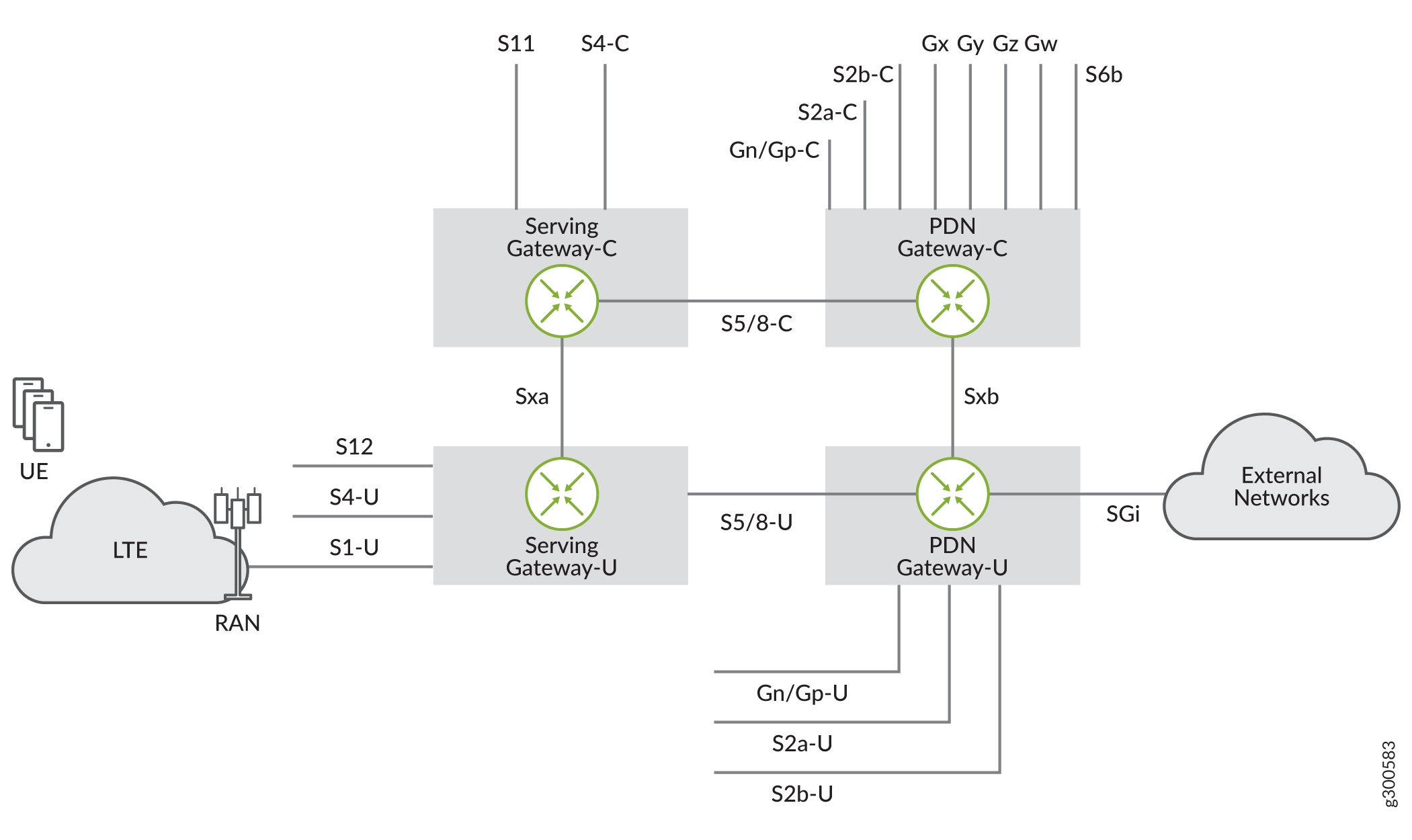
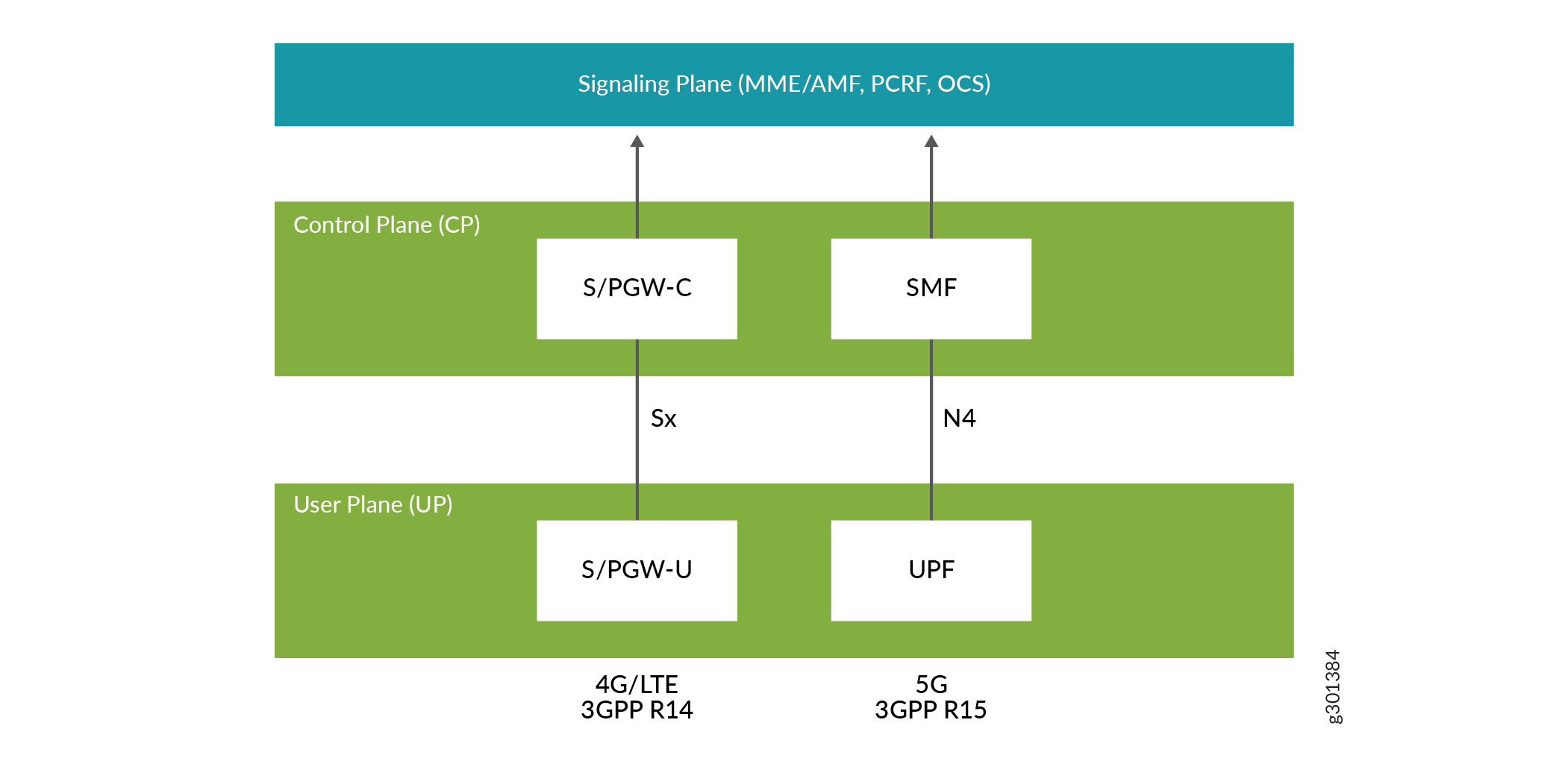
3GPP TS 29.244 Release 14 introduced CUPS, which stands for Control and User Plane Separation. CUPS provides the architecture enhancements for the separation of functionality in the EPC’s serving gateway (SGW) and PDN gateway (PGW). As Figure 2 shows, both the SGW and the PGW of the EPC can be separated into their control plane and user plane functions. CUPS introduces new interfaces, Sxa and Sxb, between the control plane and user plane functions of the SGW and PGW, respectively. CUPS enables control plane and user plane functions to be deployed, scaled and operated separately while integrated over a standard reference interface.
The control plane provides the following functionality:
Receives traffic rules and actions
Triggers accounting
Makes session level announcements
Receives usage information
Receives user plane status information
Northbound integration with the signaling plane
Configures and enables Lawful Intercept sessions
The user plane provides the following functionality:
Subscriber tunnel encapsulations (GTP-U)
Packet routing and forwarding
QoS and buffering
Policy enforcement
Statistics gathering and reporting
Enacts Lawful Intercept requests
Optional advanced services
With this functional separation, the control plane and the user plane have very distinct deployment requirements and can be in different physical locations. While the control plane function is very complex, the user plane function requires high packet processing capability and rich policy enforcement. You can distribute the user plane more than the control plane and locate the user plane closer to end-user access points. This distribution enables higher bandwidth per user while delivering lower latency. Control plane and user plane separation provides the following benefits:
Independent scaling of the user plane and the control plane
Network architecture flexibility including:
Ability to deploy from the edge to the core.
Ability to segregate different traffic types and services across different user planes while maintaining a common or single control plane.
Operational flexibility
Easier migration path from 4G to 5G services. CUPS is optional for 4G, but is an integral part of the 5G network architecture.
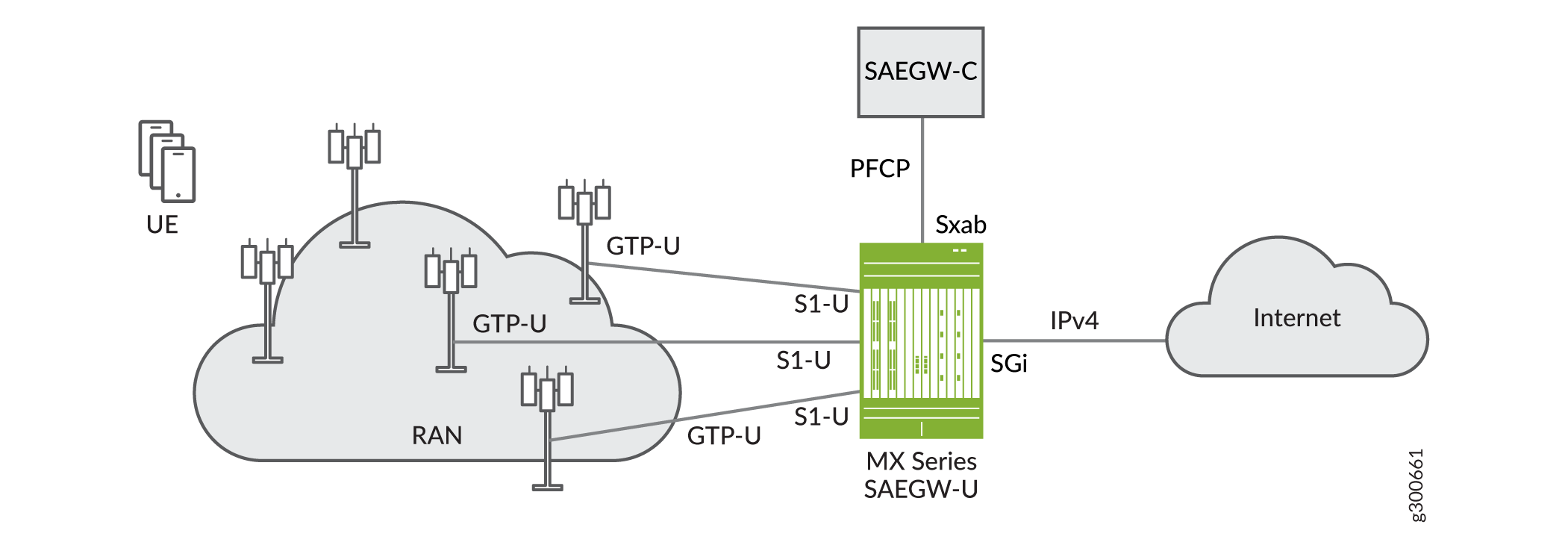
Junos Multi-Access User Plane supports a combined SGW user plane (SGW-U) and PGW user plane (PGW-U) in a single MX series router (see Figure 3). The combined SGW-U/PGW-U is referred to as a SAEGW-U (System Architecture Evolution Gateway-User Plane). Juniper’s MX SAEGW-U can interoperate with a third-party combined SGW-C/PGW-C, referred to as a SAEGW-C, through a combined Sxab interface.
Juniper’s MX SAEGW-U communicates with the third-party SAEGW-C over the Sxab interface through Packet Forwarding Control Protocol (PFCP) as specified in 3GPP TS 29.244.
Junos Multi-Access User Plane also supports running an MX router as either a standalone SGW-U or a standalone PGW-U. A standalone SGW-U enables high-throughput 4G mobility service (relocation of a UE to a new eNodeB, new SGW-U, or new SAEGW-U). Junos Multi-Access User Plane support GTP-U based S5-U and S8-U interfaces, which are links between SGW-U and PGW-U devices. Junos Multi-Access User Plane also provides tunnel relay functionality to forward user plane traffic between S1-U and S5-U/S8-U interfaces and between S5-U/S8-U and SGi interfaces.
Figure 4 shows the basic topology of running MX routers separately as and SGW-U and a PGW-U to enable mobility.
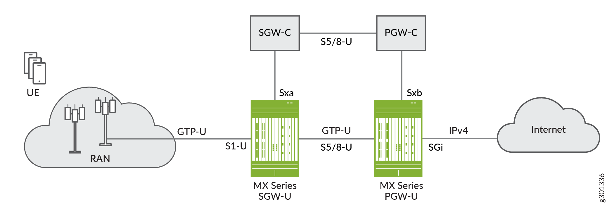
SGW-Cs and PGW-Cs handle logistics of UE handover, including SGW & PGW selection. The SGW-C and PGW-C participate in control protocol exchanges and update their SGW-U/PGW-U counterparts with any new or changed attributes of the UE session and bearers.
We support the following mobility scenarios:
-
Handover with eNodeB and no SGW change
-
Handover with SGW change (direct forwarding)
-
Handover with SGW change (indirect forwarding)
Junos Multi-Access User Plane supports 5G user plane function (UPF) in addition to the SAEGW-U/SGW-U/PGW-U functions (see Figure 5). Junos Multi-Access User Plane supports seamless transition from 4G to 5G services by supporting both networks on the same MX Series router with the same configuration. Junose Multi-Access User Plane supports 4G sessions and 5G sessions simultaneously.
Junos Multi-Access User Plane supports MX routers functioning as user plane functions (UPFs) in accordance with 3GPP Release 15 CUPS architecture. The UPF provides high-throughput 5G fixed wireless and mobile wireless service in non-standalone (NSA) mode.
Figure 6 shows the basic topology of running an MX router as a UPF to enable 5G services.
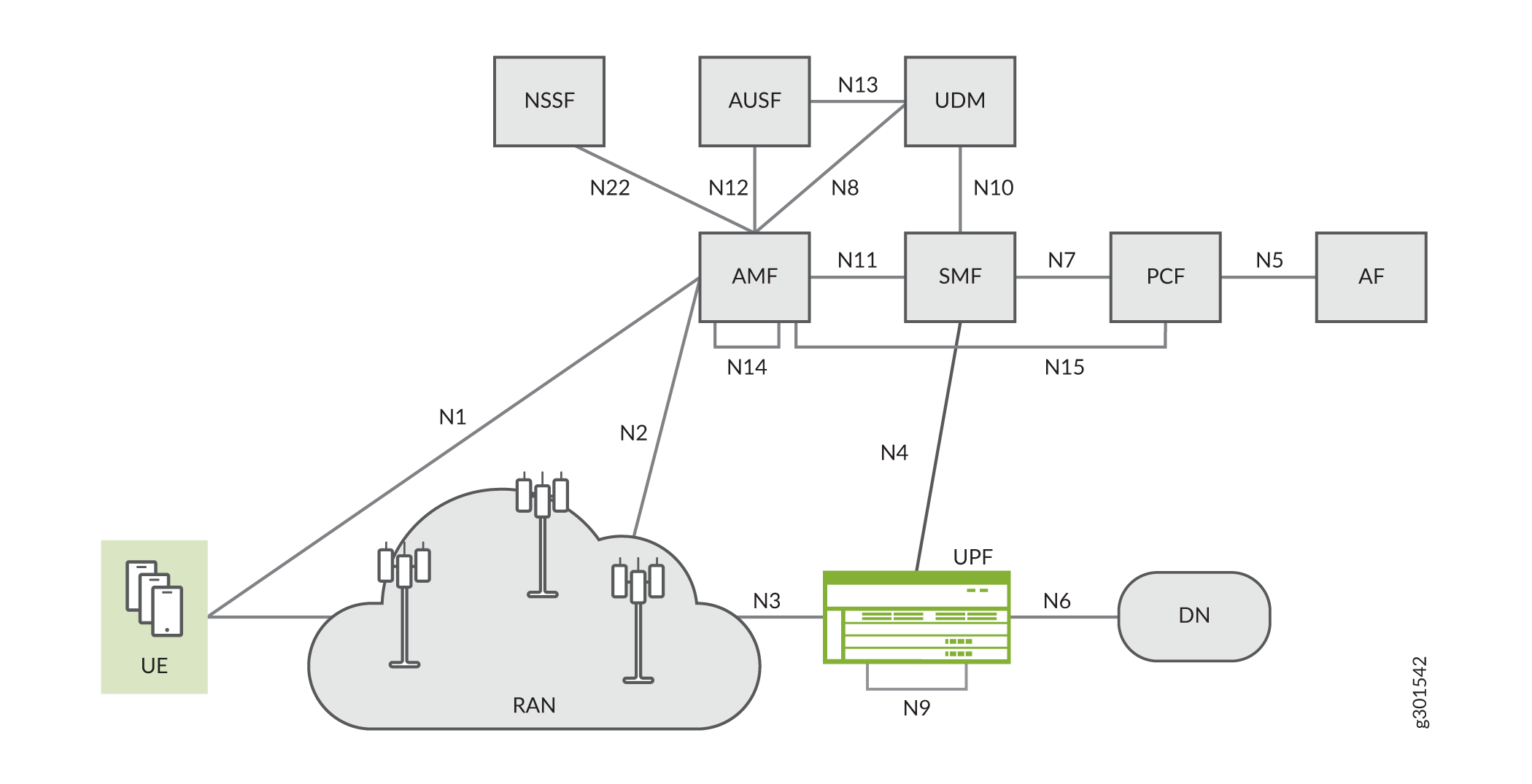
The 5G system architecture consists of the following network functions:
-
Authentication Server Function (AUSF)
-
Access and Mobility Management Function (AMF)
-
Data Network (DN), e.g. operator services, Internet access or 3rd party services
-
Network Slice Selection Function (NSSF)
-
Policy Control Function (PCF)
-
Session Management Function (SMF)
-
Unified Data Management (UDM)
-
User Plane Function (UPF)
-
Application Function (AF)
-
User Equipment (UE)
-
(Radio) Access Network ((R)AN)
The session management function (SMF) includes the following functionality. A single instance of an SMF can support some or all of the SMF functionalities.
-
Session management, e.g. session establishment, modify and release, including tunnel maintain between the UPF and a RAN node
-
UE IP address allocation and management (including optional authorization)
-
DHCPv4 (server and client) and DHCPv6 (server and client) functions
-
Selection and control of the UPF
-
Configure traffic steering at the UPF to route traffic to the proper destination
-
Termination of interfaces towards policy control functions
-
Charging data collection and support of charging interfaces
-
Control and coordination of charging data collection at UPF
-
Termination of SM parts of NAS messages
-
Downlink data notification
-
Initiator of RAN-specific SM information, sent via AMF over N2 to AN
-
Determine SSC mode of a session
-
Roaming functionality:
-
Handle local enforcement to apply QoS SLAs (VPLMN)
-
Charging data collection and charging interface (VPLMN)
-
Support for interaction with external DN for transport of signaling for PDU session authentication/authorization by external DN
-
The user plane function (UPF) includes the following functionality. A single instance of a UPF can support some or all of the UPF functionalities.
-
Anchor point for Intra-/Inter-RAT mobility (when applicable)
-
External PDU session point of interconnect to the data network
-
Packet routing and forwarding
-
Packet inspection
-
User plane part of policy rule enforcement, e.g., gating, redirection, traffic steering)
-
Traffic usage reporting
-
QoS handling for user plane, e.g. uplink/downlink rate enforcement, reflective QoS marking in the downlink direction
-
Uplink traffic verification (SDF to QoS Flow mapping)
-
Transport level packet marking in the uplink and the downlink directions
-
Downlink packet buffering and downlink data notification triggering
-
Sending and forwarding of one or more end marker messages to the source RAN node
Junos Multi-Access User Plane acts as the UPF in the 5G CUPs architecture and includes support for the following:
- N3, N4, N6, and N9 interface support
- Roaming through the N9 interface
- GPRS tunneling protocol, user plane (GTP-U) tunneling to the control plane
- QoS Flow ID (QFI) support for 5G QoS flows
N3, N4, and N6 interfaces are similar to S1-U, Sx, and SGi interfaces in the 4G CUPs architecture, respectively. The N9 interface is similar to the S5/8-U interface. The N9 interface carries GTP-U encapsulated traffic and only connects from one UPF to another. In home-routed roaming scenarios, N9 reference points carry the user plane traffic back to an anchor UPF in the Home Public Land Mobile Network (HPLMN). Junos Multi-Access User Plane supports either a single N9 reference point or a single N6 reference point per PDU session.
QoS in 4G networks is bearer-based where the mapping is one to one between a bearer and a radio bearer. QoS in 5G networks is flow-based where a QFI (QoS Flow Identifier) classifies and marks packets. Multiple QoS flows map to a radio bearer. Each QoS flow is associated with two parameters, a 5G QoS Identifier (5QI) and an allocation and retention priority (ARP).
In summary, starting with Junos OS Release 21.2R1, Junos Multi-Access User Plane supports four different modes of operation on a single MX router:
-
SGW-U, where the MX router acts as an SGW-U for all sessions and connects to a third-party SGW-C over a single Sxa interface and Juniper or third party PGW-Us over multiple S5/8-U interfaces.
-
PGW-U, where the MX router acts as a PGW-U for all sessions and connects to a third-party PGW-C over a single Sxb interface and Juniper or third-party SGW-Us over multiple S5/8-U interfaces.
-
Combined SGW/PGW-U (SAEGW-U), where depending on the UE location, the MX router acts as an SGW-U for some sessions, a PGW-U for another set of sessions and SAEGW-U for the remaining sessions. In this mode, the SAEGW-U connects to an SAEGW-C over a single Sxab interface and to other Juniper or third-party SGW-Us and PGW-Us over multiple S5/8-U interfaces.
-
UPF, where the MX router acts as a UPF for all sessions and connects to a third-party SMF over a single N4 interface and to other Juniper or third-party UPFs over multiple N9 interfaces.
3GPP TS 29.244 Release 15 Support
Junos Multi-Access User Plane supports elements of 3GPP TS 29.244 Release 15, including support for the following functionality:
PDI Optimization Support—Packet Detection Information (PDI) optimization is an optional feature that enables the control plane function (CPF) to optimize the signaling towards the UPF by combining the information that is common to multiple Packet Detection Rules (PDRs) as a Traffic Endpoint with a Traffic Endpoint ID (TEID) and then referring to this Traffic Endpoint in messaging. The Traffic Endpoint ID is unique within a PFCP session.
GTP Path Management—GTP path management provides heartbeat and error indication over GTP-U interfaces. A GTP-U peer can send an echo request on a path to a GTP-U peer to find out if it is alive. Junos Multi-Access User Plane devices support responding to echo requests.
User ID Support—The user ID is an information element (IE) that can be present in a PFCP Session Establishment Request. This IE is useful for troubleshooting problems in the UPF affecting a subscriber. The IE is visible in the output for the
show services mobile-edge sessions extensivecommand. The user ID is an optional, noncritical IE that can be any length up to 16 digits or 8 characters.Transport Level Marking—For EPC, the SGW and PGW perform transport level marking on a per EPS bearer basis. Transport level marking is the process of marking traffic with a DSCP value based on the locally configured mapping from the QCI and optionally the ARP level. The CPF can change the transport level marking by changing the Transport Level Marking IE in the related Forwarding Action Rule (FAR).
Note:Juniper Multi-Access User Plane supports transport level marking per bearer for downlink data only.
Transport Level Marking—For 5GC (5G core), transport level marking occurs on a per QoS flow basis. Transport level marking is the process of marking traffic at the UPF with a DSCP value based on the mapping from the 5QI, the priority level (if explicitly signaled) and, optionally, the ARP priority level configured at the SMF.
DDOS Support—DDOS support is provided for PFCP and GTP path management. To configure DDOS for these protocols, see protocols (DDoS) .
QoS control/enforcement at the bearer level—For QoS control/enforcement at the bearer level, the CPF must create the necessary PRDs to represent the service data flow, bearer, or session. The CPF must also create QERs for the QoS enforcement of the aggregate of the SDFs with the same bearer.
Junos Multi-Access User Plane supports QoS enforcement at either the service data flow (SDF) or the bearer level. If the MX router as UPF receives more than one QER for a bearer, it enforces QoS at the SDF level. If the MX router as UPF receives one QER for a bearer, it enforces QoS at the bearer level.
Hardware and Software Requirements
This section lists the MX Series hardware and software requirements needed to implement Junos Multi-Access User Plane.
Table 1 describes the hardware and software requirements for the Junos Multi-Access User Plane solution.
Junos OS Release |
Supported Platforms |
Line Cards Supporting Anchor PFE Interfaces |
Line Cards Supporting Signaling, Ingress, and Egress Interfaces |
Supported Routing Engines |
|---|---|---|---|---|
|
Starting in Junos OS Release 19.4R1 |
|
|
|
|
|
Starting in Junos OS Release 20.2R1 |
|
|
|
|
|
Starting in Junos OS Release 22.3R1 |
|
|
|
|
|
Starting in Junos OS Release 23.2R1 |
|
|
|
|
|
Note:
One MPC7 line card contains up to two anchor PFE interfaces. Note:
MX204 routers do not support GRES or APFE redundancy. |
||||
Change History Table
Feature support is determined by the platform and release you are using. Use Feature Explorer to determine if a feature is supported on your platform.