Example: Configuring LDP Link Protection
LDP Link Protection Overview
- Understanding Multipoint Extensions to LDP
- Using Multipoint Extensions to LDP on Targeted LDP Sessions
- Current Limitations of LDP Link Protection
- Using RSVP LSP as a Solution
- Understanding Multicast LDP Link Protection
- Different Modes for Providing LDP Link Protection
- Label Operation for LDP Link Protection
- Sample Multicast LDP Link Protection Configuration
- Make-Before-Break
- Caveats and Limitations
Understanding Multipoint Extensions to LDP
An LDP defines mechanisms for setting up point-to-point, multipoint-to-point, point-to-multipoint, and multipoint-to-multipoint LSPs in the network. The point-to-multipoint and multipoint-to-multipoint LSPs are collectively referred to as multipoint LSPs, where traffic flows from a single source to multiple destinations, and from multiple sources to multiple destinations, respectively. The destination or egress routers are called leaf nodes, and traffic from the source traverses one or more transit nodes before reaching the leaf nodes.
Junos OS does not provide support for multipoint-to-multipoint LSPs.
By taking advantage of the MPLS packet replication capability of the network, multipoint LSPs avoid unnecessary packet replication at the ingress router. Packet replication takes place only when packets are forwarded to two or more different destinations requiring different network paths.
Using Multipoint Extensions to LDP on Targeted LDP Sessions
The specification for the multipoint extensions to LDP requires that the two endpoints of an LDP session are directly connected by a Layer 2 medium, or are considered to be neighbors by the network's IGP. This is referred to as an LDP link session. When the two endpoints of an LDP session are not directly connected, the session is referred to as a targeted LDP session.
Past Junos OS implementations support multicast LDP for link sessions only. With the introduction of the LDP link protection feature, the multicast LDP capabilities are extended to targeted LDP sessions. Figure 1 shows a sample topology.
Routers R7 and R8 are the upstream (LSR-U) and downstream (LSR-D) label-switched routers (LSRs), respectively, and deploy multicast LDP. The core router, Router R5, has RSVP-TE enabled.
When LSR-D is setting up the point-to-multipoint LSP with root and LSP ID attributes, it determines the upstream LSR-U as a next-hop on the best path to the root (currently, this next-hop is assumed to be an IGP next hop).
With the multicast LDP support on targeted LDP sessions, you can determine if there is an LSP next hop to LSR-U which is on LSR-D's path to root, where LSR-D and LSR-U are not directly connected neighbors, but targeted LDP peers. The point-to-multipoint label advertised on the targeted LDP session between LSR-D and LSR-U is not used unless there is an LSP between LSR-D and LSR-U. Therefore, a corresponding LSP in the reverse direction from LSR-U to LSR-D is required.
Data is transmitted on the point-to-multipoint LSP using unicast replication of packets, where LSR-U sends one copy to each downstream LSR of the point-to-multipoint LSP.
The data transmission is implemented in the following ways:
-
The point-to-multipoint capabilities on the targeted LDP session are negotiated.
-
The algorithm to select the upstream LSR is changed, where if IGP next hops are unavailable, or in other words, there is no LDP link session between LSR-D and LSR-U, an RSVP LSP is used as the next hop to reach LSR-U.
-
The incoming labels received over the targeted LDP sessions are installed as a branch next hop for this point-to-multipoint FEC route with the LDP label as the inner label and the RSVP label as the outer label.
Current Limitations of LDP Link Protection
When there is a link or node failure in an LDP network deployment, fast traffic recovery should be provided to recover impacted traffic flows for mission-critical services. In the case of multipoint LSPs, when one of the links of the point-to-multipoint tree fails, the subtrees might get detached until the IGP reconverges and the multipoint LSP is established using the best path from the downstream router to the new upstream router.
In fast reroute using local repair for LDP traffic, a backup path (repair path) is pre-installed in the Packet Forwarding Engine. When the primary path fails, traffic is rapidly moved to the backup path without having to wait for the routing protocols to converge. Loop-free alternate (LFA) is one of the methods used to provide IP fast reroute capability in the core and service provider networks.
Without LFA, when a link or a router fails or is returned to service, the distributed routing algorithms compute the new routes based on the changes in the network. The time during which the new routes are computed is referred to as routing transition. Until the routing transition is completed, the network connectivity is interrupted because the routers adjacent to a failure continue to forward the data packets through the failed component until an alternative path is identified.
However, LFA does not provide full coverage in all network deployments because of the IGP metrics. As a result, this is a limitation to the current LDP link protection schemes.
Figure 2 illustrates a sample network with incomplete LFA coverage, where traffic flows from the source router (S) to the destination router (D) through Router R1. Assuming that each link in the network has the same metric, if the link between the Router S and Router R1 fails, Router R4 is not an LFA that protects the S-R1 link, so traffic resiliency is lost. Thus, full coverage is not achieved by using plain LFA. In typical networks, there is always some percentage of LFA coverage gap with plain LFA.
Using RSVP LSP as a Solution
The key to protect the traffic flowing through LDP LSPs is to have an explicit tunnel to re-route the traffic in the event of a link or node failure. The explicit path has to terminate on the next downstream router, and the traffic needs to be accepted on the explicit path, where the RPF check should pass.
RSVP LSPs help overcome the current limitations of loop-free alternate (LFA) for both point-to-point and point-to-multipoint LDP LSPs by extending the LFA coverage in the following methods:
Manually Configured RSVP LSPs
Considering the example used in Figure 2, when the S-R1 link fails, and Router R4 is not an LFA for that particular link, a manually created RSVP LSP is used as a patch to provide complete LFA coverage. The RSVP LSP is pre-signaled and pre-installed in the Packet Forwarding Engine of Router S, so that it can be used as soon as Router S detects that the link has failed.
In this case, an RSVP LSP is created between Routers S, R4, and R3 as illustrated in Figure 3. A targeted LDP session is created between Router S and Router R3, as a result of which, when the S-R1 link fails, traffic reaches Router R3. Router R3 forwards the traffic to Router R2, as it is the shortest path to reach the destination, Router D.
Dynamically Configured RSVP LSPs
In this method, the RSVP LSPs are created automatically and pre-installed in the system so that they can be used immediately when there is a link failure. Here, the egress is the node on the other side of the link being protected, thereby improving the LFA coverage.
Benefits of Enabling Dynamic RSVP LSPs
-
Ease of configuration.
-
100 percent coverage against link failure as long as there is an alternate path to the far end of the link being protected.
-
Setting up and tearing down of the RSVP bypass LSP is automatic.
-
RSVP LSP only used for link protection and not for forwarding traffic while the link being protected is up.
-
Reduces the total number of RSVP LSPs required on the system.
Considering the example used in Figure 2, in order to protect traffic against the potential failure of the S-R1 link, because Router R4 is not an LFA for that particular link, an RSVP bypass LSP is automatically created to Router R1, which is the node on the far side of the protected link as illustrated in Figure 4. From Router R1, traffic is forwarded to its original destination, Router D.
The RSVP LSP is pre-signaled and pre-installed in the Packet Forwarding Engine of Router S so that it can be used as soon as Router S detects that the link has failed.
An alternative mode of operation is not to use LFA at all, and to always have the RSVP LSP created to cover all link failures.
To enable dynamic RSVP LSPs, include the dynamic-rsvp-lsp statement at the [edit protocols ldp interface interface-name link-protection] hierarchy level, in addition to enabling
the RSVP protocol on the appropriate interfaces.
Understanding Multicast LDP Link Protection
A point-to-multipoint LDP label-switched path (LSP) is an LDP-signaled LSP that is point-to-multipoint, and is referred to as multicast LDP.
A multicast LDP LSP can be used to send traffic from a single root or ingress node to a number of leaf or egress nodes traversing one or more transit nodes. Multicast LDP link protection enables fast reroute of traffic carried over point-to-multipoint LDP LSPs in case of a link failure. When one of the links of the point-to-multipoint tree fails, the subtrees might get detached until the IGP reconverges and the multipoint LSP is established using the best path from the downstream router to the new upstream router.
To protect the traffic flowing through the multicast LDP LSP, you can configure an explicit tunnel to re-route the traffic in the event of link failure. The explicit path has to terminate on the next downstream router. The reverse path forwarding for the traffic should be successful.
Multicast LDP link protection introduces the following features and functionality:
-
Use of dynamic RSVP LSP as bypass tunnels
The RSVP LSP's Explicit Route Object (ERO) is calculated using Constrained Shortest Path First (CSPF) with the constraint as the link to avoid. The LSP is signaled and torn down dynamically whenever link protection is necessary.
-
Make-before-break
The make-before-break feature ensures that there is minimum packet loss when attempting to signal a new LSP path before tearing down the old LSP path for the multicast LDP LSP.
-
Targeted LDP session
A targeted adjacency to the downstream label-switching router (LSR) is created for two reasons:
-
To keep the session up after link failure.
-
To use the point-to-multipoint label received from the session to send traffic to the downstream LSR on the RSVP LSP bypass tunnel.
When the downstream LSR sets up the multicast LDP LSP with the root node and LSP ID, it uses that upstream LSR, which is on the best path toward the root.
-
Multicast LDP link protection is not required when there are multiple link adjacencies (parallel links) to the downstream LSR.
Different Modes for Providing LDP Link Protection
Following are three different modes of operation available for unicast and multicast LDP link protection:
-
Case A: LFA only
Under this mode of operation, multicast LDP link protection is provided using an existing viable loop-free alternate (LFA). In the absence of a viable LFA, link protection is not provided for the multicast LDP LSP.
-
Case B: LFA and Dynamic RSVP LSP
Under this mode of operation, multicast LDP link protection is provided using an existing viable LFA. In the absence of a viable LFA, an RSVP bypass LSP is created automatically to provide link protection for the multicast LDP LSP.
-
Case C: Dynamic RSVP LSP only
Under this mode of operation, LFA is not used for link protection. Multicast LDP link protection is provided by using automatically created RSVP bypass LSP.
Figure 5 is a sample topology illustrating the different modes of operation for multicast LDP link protection. Router R5 is the root connecting to two leaf nodes, Routers R3 and R4. Router R0 and Router R1 are the upstream and downstream label-switched routers (LSRs), respectively. A multicast LDP LSP runs among the root and leaf nodes.
Considering that Router R0 needs to protect the multicast LDP LSP in the case that the R0-R1 link fails, the different modes of link protection operate in the following manner:
-
Case A: LFA only
Router R0 checks if a viable LFA path exists that can avoid the R0-R1 link to reach Router R1. Based on the metrics, Router R2 is a valid LFA path for the R0-R1 link and is used to forward unicast LDP traffic. If multiple multicast LDP LSPs use the R0-R1 link, the same LFA (Router R2) is used for multicast LDP link protection.
When the R0-R1 link fails, the multicast LDP LSP traffic is moved onto the LFA path by Router R0, and the unicast LDP label to reach Router R1 (L100) is pushed on top of the multicast LDP label (L21).
-
Case B: LFA and Dynamic RSVP LSP
Router R0 checks if a viable LFA path exists that can avoid the R0-R1 link to reach Router R1. Based on the metrics, Router R2 is a valid LFA path for the R0-R1 link and is used to forward unicast LDP traffic. If multiple multicast LDP LSPs use the R0-R1 link, the same LFA (Router R2) is used for multicast LDP link protection. When the R0-R1 link fails, the multicast LDP LSP traffic is moved onto the LFA path by Router R0.
However, if the metric on the R2-R1 link was 50 instead of 10, Router 2 is a not a valid LFA for the R0-R1 link. In this case, an RSVP LSP is automatically created to protect the multicast LDP traffic traveling between Routers R0 and R1.
-
Case C: Dynamic RSVP LSP only
An RSVP LSP is signaled automatically from Router R0 to Router R1 through Router R2, avoiding interface ge-1/1/0. If multiple multicast LDP LSPs use the R0-R1 link, the same RSVP LSP is used for multicast LDP link protection.
When the R0-R1 link fails, the multicast LDP LSP traffic is moved onto the RSVP LSP by Router R0, and the RSVP label to reach Router R1 (L100) is pushed on top of the multicast LDP label (L21).
Label Operation for LDP Link Protection
Using the same network topology as in Figure 5, Figure 6 illustrates the label operation for unicast and multicast LDP link protection.
Router R5 is the root connecting to two leaf nodes, Routers R3 and R4. Router R0 and Router R1 are the upstream and downstream label-switched routers (LSRs), respectively. A multicast LDP LSP runs among the root and leaf nodes. An unicast LDP path connects Router R1 to Router R5.
The label operation is performed differently under the following modes of LDP link protection:
Case A: LFA Only
Using the show route detail command output on Router
R0, the unicast LDP traffic and multicast LDP traffic can be derived.
user@R0> show route detail
299840 (1 entry, 1 announced)
        *LDP    Preference: 9
                Next hop type: Router
                Address: 0x93bc22c
                Next-hop reference count: 1
                Next hop: 11.0.0.6 via ge-0/0/1.0 weight 0x1, selected
                Label operation: Swap 299824
                Session Id: 0x1
                Next hop: 11.0.0.10 via ge-0/0/2.0 weight 0xf000
                Label operation: Swap 299808
                Session Id: 0x3
                State: <Active Int>
                Age: 3:16        Metric: 1
                Validation State: unverified
                Task: LDP
                Announcement bits (1): 0-KRT
                AS path: I
                Prefixes bound to route: 192.168.0.4/32

299856 (1 entry, 1 announced)
        *LDP    Preference: 9
                Next hop type: Flood
                Address: 0x9340e04
                Next-hop reference count: 3
                Next hop type: Router, Next hop index: 262143
                Address: 0x93bc3dc
                Next-hop reference count: 2
                Next hop: 11.0.0.6 via ge-0/0/1.0 weight 0x1
                Label operation: Swap 299888
                Next hop: 11.0.0.10 via ge-0/0/2.0 weight 0xf000
                Label operation: Swap 299888, Push 299776(top)
                Label TTL action: prop-ttl, prop-ttl(top)
                State: <Active Int AckRequest>
                Age: 3:16       Metric: 1
                Validation State: unverified
                Task: LDP
                Announcement bits (1): 0-KRT
                AS path: I
                FECs bound to route: P2MP root-addr 192.168.0.5, lsp-id 99
Label 299840 is traffic arriving at Router R0 that corresponds to unicast LDP traffic to Router R1. Label 299856 is traffic arriving at Router 0 that corresponds to multicast LDP traffic from the root node R5 to the leaf egress nodes, R3 and R4.
The main path for both unicast and multicast LDP LSPs is through interface ge-0/0/1 (the link to Router R1), and the LFA path is through interface ge-0/0/2 (the link to Router R2). The LFA path is not used unless the ge-0/0/1 interface goes down.
In the label operation for Case A, the LFA-only mode of operation is different for unicast and multicast LDP traffic:
-
Unicast label operation
For unicast LDP traffic, the FECs and associated labels are advertised on all the links in the network on which LDP is enabled. This means that in order to provide LFA action for the unicast LDP traffic to Router R4, instead of swapping the incoming label for label 299824 advertised by Router R1 for FEC R4, Router R0 simply swaps the incoming label for label 299808 advertised by Router R2 for FEC R4. This is the standard Junos OS LFA operation for unicast LDP traffic.
Figure 7 illustrates the label operation for unicast traffic when the R0-R1 link fails. The grey boxes show the label operation for unicast LDP traffic under normal condition, and the dotted boxes show the label operation for unicast LDP traffic when the R0-R1 link fails.
Figure 7: Unicast LDP Label Operation
-
Multicast label operation
The label operation for multicast LDP traffic differs from the unicast LDP label operation, because multipoint LSP labels are only advertised along the best path from the leaf node to the ingress node. As a result, Router R2 has no knowledge of the multicast LDP. To overcome this, the multicast LDP LSP traffic is simply tunneled inside the unicast LDP LSP path through Router R2 that terminates at Router R1.
In order to achieve this, Router R0 first swaps the incoming multicast LDP LSP label 299856 to label 299888 advertised by Router R1. Label 299776 is then pushed on top, which is the LDP label advertised by Router R2 for FEC R1. When the packet arrives at Router R2, the top label is popped out due to penultimate hop-popping. This means that the packet arrives at Router R1 with the multicast LDP label 299888 that Router R1 had originally advertised to Router R0.
Figure 8 illustrates the label operation for multicast LDP traffic when the R0-R1 link fails. The blue boxes show the label operation for multicast LDP traffic under normal condition, and the dotted boxes show the label operation for multicast LDP traffic when the R0-R1 link fails.
Figure 8: Multicast LDP Label Operation
When the metric on the R2-R1 link is set to 1000 instead of 1, Router R2 is not a valid LFA for Router R0. In this case, if Router R2 receives a packet destined for Router R1, R3, or R4 before its IGP has converged, the packet is sent back to Router R0, resulting in looping packets.
Because Router R0 has no viable LFA, no backup paths are installed in the Packet Forwarding Engine. If the R0-R1 link fails, traffic flow is interrupted until the IGP and LDP converge and new entries are installed on the affected routers.
The show route detail command displays the state
when no LFA is available for link protection.
user@host> show route detail
299840 (1 entry, 1 announced)
        *LDP    Preference: 9
                Next hop type: Router, Next hop index: 578
                Address: 0x9340d20
                Next-hop reference count: 2
                Next hop: 11.0.0.6 via ge-0/0/1.0, selected
                Label operation: Swap 299824
                Session Id: 0x1
                State: <Active Int>
                Age: 5:38       Metric: 1
                Validation State: unverified
                Task: LDP
                Announcement bits (1): 0-KRT
                AS path: I
                Prefixes bound to route: 192.168.0.4/32

299856 (1 entry, 1 announced)
        *LDP    Preference: 9
                Next hop type: Flood
                Address: 0x9340e04
                Next-hop reference count: 3
                Next hop type: Router, Next hop index: 579
                Address: 0x93407c8
                Next-hop reference count: 2
                Next hop: 11.0.0.6 via ge-0/0/1.0
                Label operation: Swap 299888
                State: <Active Int AckRequest>
                Age: 5:38       Metric: 1
                Validation State: unverified
                Task: LDP
                Announcement bits (1): 0-KRT
                AS path: I
                FECs bound to route: P2MP root-addr 192.168.0.5, lsp-id 99
Case B: LFA and Dynamic RSVP LSP
In this mode of operation, if there is a viable LFA neighbor, the label operation behavior is similar to that of Case A, LFA only mode. However, if there is no viable LFA neighbor, an RSVP bypass tunnel is automatically created.
If the metric on the link R2-R1 is set to 1000 instead of 1, Router R2 is not an LFA for Router R0. On learning that there are no LFA paths to protect the R0-R1 link failure, an RSVP bypass tunnel is automatically created with Router R1 as the egress node and follows a path that avoids the R0-R1 link (for instance, R0-R2-R1).
If the R0-R1 link fails, the unicast LDP and multicast LDP traffic is tunneled through the RSVP bypass tunnel. The RSVP bypass tunnel is not used for normal forwarding and is used only to provide link protection to LDP traffic in the case of R0-R1 link failure.
Using the show route detail command, the unicast
and multicast LDP traffic can be derived.
user@host> show route detail
299840 (1 entry, 1 announced)
        *LDP    Preference: 9
                Next hop type: Router
                Address: 0x940c3dc
                Next-hop reference count: 1
                Next hop: 11.0.0.6 via ge-0/0/1.0 weight 0x1, selected
                Label operation: Swap 299824
                Session Id: 0x1
                Next hop: 11.0.0.10 via ge-0/0/2.0 weight 0x8001
                Label-switched-path ge-0/0/1.0:BypassLSP->192.168.0.1
                Label operation: Swap 299824, Push 299872(top)
                Label TTL action: prop-ttl, prop-ttl(top)
                Session Id: 0x3
                State: <Active Int NhAckRequest>
                Age: 19         Metric: 1
                Validation State: unverified
                Task: LDP
                Announcement bits (1): 0-KRT
                AS path: I
                Prefixes bound to route: 192.168.0.4/32

299856 (1 entry, 1 announced)
        *LDP    Preference: 9
                Next hop type: Flood
                Address: 0x9340e04
                Next-hop reference count: 3
                Next hop type: Router, Next hop index: 262143
                Address: 0x940c154
                Next-hop reference count: 2
                Next hop: 11.0.0.6 via ge-0/0/1.0 weight 0x1
                Label operation: Swap 299888
                Next hop: 11.0.0.10 via ge-0/0/2.0 weight 0x8001
                Label-switched-path ge-0/0/1.0:BypassLSP->192.168.0.1
                Label operation: Swap 299888, Push 299872(top)
                Label TTL action: prop-ttl, prop-ttl(top)
                State: < Active Int AckRequest>
                Age: 20         Metric: 1
                Validation State: unverified
                Task: LDP
                Announcement bits (1): 0-KRT
                AS path: I
                FECs bound to route: P2MP root-addr 192.168.0.5, lsp-id 99
The main path for both unicast and multicast LDP LSP is through interface ge-0/0/1 (the link to Router R1), and the LFA path is through interface ge-0/0/2 (the link to Router R2). The LFA path is not used unless the ge-0/0/1 interface goes down.
Label 299840 is traffic arriving at Router R0 that corresponds to unicast LDP traffic to Router R4. Label 299856 is traffic arriving at Router 0 that corresponds to multicast LDP traffic from the root node R5 to the leaf egress nodes, R3 and R4.
As seen in the show route detail command output,
the label operations for the protection path are the same for unicast
LDP and multicast LDP traffic. The incoming LDP label at Router R0
is swapped to the LDP label advertised by Router R1 to Router R0.
The RSVP label 299872 for the bypass tunnel is then pushed onto the
packet. Penultimate hop-popping is used on the bypass tunnel, causing
Router R2 to pop that label. Thus the packet arrives at Router R1
with the LDP label that it had originally advertised to Router R0.
Figure 9 illustrates the label operation for unicast LDP and multicast LDP traffic protected by the RSVP bypass tunnel. The grey and blue boxes represent label values used under normal conditions for unicast and multicast LDP traffic, respectively. The dotted boxes represent label values used when the R0-R1 link fails.
Case C: Dynamic RSVP LSP Only
In this mode of operation, LFA is not used at all. A dynamic
RSVP bypass LSP is automatically created in order to provide link
protection. The output from the show route detail command
and the label operations are similar to Case B, LFA and dynamic RSVP
LSP mode.
Sample Multicast LDP Link Protection Configuration
To enable multicast LDP link protection, the following configuration is required on Router R0:
In this sample, multicast LDP link protection is enabled on the ge-1/0/0 interface of Router R0 that connects to Router R1, although typically all the interfaces need to be configured for link protection.
Router R0
protocols {
    rsvp {
        interface all;
        interface ge-0/0/0.0 {
            disable;
        }
    }
    mpls {
        interface all;
        interface ge-0/0/0.0 {
            disable;
        }
    }
    ospf {
        traffic-engineering;
        area 0.0.0.0 {
            interface lo0.0;
            interface ge-0/0/1.0 {
                link-protection;
            }
            interface ge-0/0/2.0;
            interface ge-0/0/3.0;
        }
    }
    ldp {
        make-before-break {
            timeout seconds;
            switchover-delay seconds;
        }
        interface ge-1/1/0.0 {
            link-protection {
                disable;
                dynamic-rsvp-lsp;
            }
        }
    }
}
The following configuration statements apply to the different modes of multicast LDP protection as follows:
-
link-protectionstatement at[edit protocols ospf interface ge-0/0/1.0]This configuration is applied only for Case A (LFA only) and Case B (LFA and dynamic RSVP LSP) modes of multicast LDP link protection. Configuring link protection under an IGP is not required for Case C (dynamic RSVP LSP only).
-
link-protectionstatement at[edit protocols ldp interface ge-0/0/1.0]This configuration is required for all modes of multicast LDP protection. However, if the only LDP traffic present is unicast, and dynamic RSVP bypasses are not required, then this configuration is not required, as the
link-protectionstatement at the[edit protocols ospf interface ge-0/0/1.0]hierarchy level results in LFA action for the LDP unicast traffic. -
dynamic-rsvp-lspstatement at[edit protocols ldp interface ge-0/0/1.0 link-protection]This configuration is applied only for Case B (LFA and dynamic RSVP LSP) and Case C (dynamic RSVP LSP only) modes of LDP link protection. Dynamic RSVP LSP configuration does not apply to Case A (LFA only).
Make-Before-Break
The make-before-break feature is enabled by default on Junos OS and provides some benefits for point-to-multipoint LSPs.
For a point-to-multipoint LSP, a label-switched router (LSR) selects the LSR that is its next hop to the root of the LSP as its upstream LSR. When the best path to reach the root changes, the LSR chooses a new upstream LSR. During this period, the LSP might be temporarily broken, resulting in packet loss until the LSP reconverges to a new upstream LSR. The goal of make-before-break in this case is to minimize the packet loss. In cases where the best path from the LSR to the root changes but the LSP continues to forward traffic to the previous next hop to the root, a new LSP should be established before the old LSP is withdrawn to minimize the duration of packet loss.
Taking for example, after a link failure, a downstream LSR (for instance, LSR-D) still receives and/or forwards packets to the other downstream LSRs, as it continues to receive packets from the one hop RSVP LSP. Once routing converges, LSR-D selects a new upstream LSR (LSR-U) for this point-to-multipoint LSP's FEC (FEC-A). The new LSR might already be forwarding packets for FEC-A to the downstream LSRs other than LSR-D. After LSR-U receives a label for FEC-A from LSR-D, it notifies LSR-D when it has learnt that LSP for FEC-A has been established from the root to itself. When LSR-D receives such a notification, it changes its next hop for the LSP root to LSR-U. This is a route delete and add operation on LSR-D. At this point, LSR-D does an LSP switchover, and traffic tunneled through RSVP LSP or LFA is dropped, and traffic from LSR-U is accepted. The new transit route for LSR-U is added. The RPF check is changed to accept traffic from LSR-U and to drop traffic from the old upstream LSR, or the old route is deleted and the new route is added.
The assumption is that LSR-U has received a make-before-break notification from its upstream router for the FEC-A point-to-multipoint LSP and has installed a forwarding state for the LSP. At that point it should signal LSR-D by means of make-before-break notification that it has become part of the tree identified by FEC-A and that LSR-D should initiate its switchover to the LSP. Otherwise, LSR-U should remember that it needs to send notification to LSR-D when it receives a make-before-break notification from the upstream LSR for FEC-A and installs a forwarding state for this LSP. LSR-D continues to receive traffic from the old next hop to the root node using one hop RSVP LSP or LFA path until it switches over to the new point-to-multipoint LSP to LSR-U.
The make-before-break functionality with multicast LDP link protection includes the following features:
-
Make-before-break capability
An LSR advertises that it is capable of handling make-before-break LSPs using the capability advertisement. If the peer is not make-before-break capable, the make-before-break parameters are not sent to this peer. If an LSR receives a make-before-break parameter from a downstream LSR (LSR-D) but the upstream LSR (LSR-U) is not make-before-break capable, the LSR immediately sends a make-before-break notification to LSR-D, and the make-before-break capable LSP is not established. Instead, the normal LSP is established.
-
Make-before-break status code
The make-before-break status code includes:
-
1—make-before-break request
-
2—make-before-break acknowledgment
When a downstream LSR sends a label-mapping message for point-to-multipoint LSP, it includes the make-before-break status code as 1 (request). When the upstream LSR updates the forwarding state for the point-to-multipoint LSP, it informs the downstream LSR with a notification message containing the make-before-break status code as 2 (acknowledgment). At that point, the downstream LSR does an LSP switchover.
-
Caveats and Limitations
The Junos OS implementation of the LDP link protection feature has the following caveats and limitations:
-
Make-before-break is not supported for the following point-to-multipoint LSPs on an egress LSR:
-
Next-generation multicast virtual private network (MVPN) with virtual routing and forwarding (VRF) label
-
Static LSP
-
-
The following features are not supported:
-
Nonstop active routing for point-to-multipoint LSP in Junos OS Releases 12.3, 13.1 and 13.2
-
Graceful restart switchover point-to-multipoint LSP
-
Link protection for routing instance
-
Example: Configuring LDP Link Protection
This example shows how to configure Label Distribution Protocol (LDP) link protection for both unicast and multicast LDP label-switched paths (LSPs).
Requirements
This example uses the following hardware and software components:
-
Six routers that can be a combination of M Series, MX Series, or T Series routers with one root node and two leaf nodes running a point-to-multipoint LDP LSP.
-
Junos OS Release 12.3 or later running on all the routers.
Before you begin:
-
Configure the device interfaces.
-
Configure the following protocols:
-
RSVP
-
MPLS
-
OSPF or any other IGP
-
LDP
-
Overview
LDP link protection enables fast reroute of traffic carried over LDP LSPs in case of a link failure. LDP point-to-multipoint LSPs can be used to send traffic from a single root or ingress node to a number of leaf nodes or egress nodes traversing one or more transit nodes. When one of the links of the point-to-multipoint tree fails, the subtrees can get detached until the IGP reconverges and multicast LDP initiates label mapping using the best path from the downstream router to the new upstream router. To protect the traffic in the event of a link failure, you can configure an explicit tunnel so that traffic can be rerouted using the tunnel. Junos OS supports make-before-break capabilities to ensure minimum packet loss when attempting to signal a new LSP path before tearing down the old LSP path. This feature also adds targeted LDP support for multicast LDP link protection.
When configuring LDP link protection, be aware of the following considerations:
-
Configure traffic engineering under IGP (if it is not supported by default), and include the interfaces configured for MPLS and RSVP so that constrained-based link protected dynamic RSVP LSP is signaled by RSVP using Constrained Shortest Path First (CSPF). When this condition is not satisfied, RSVP LSP might not come up and LDP cannot use it as a protected next hop.
-
Configure a path between two label-switched routers (LSRs) to provide IP connectivity between the routers when there is a link failure. This enables CSPF to calculate an alternate path for link protection. When the connectivity between the routers is lost, the LDP targeted adjacency does not come up and dynamic RSVP LSP cannot be signaled, resulting in no protection for the LDP forwarding equivalence class (FEC) for which the peer is the downstream LSR.
-
If link protection is active only on one LSR, then the other LSR should not be configured with the
strict-targeted-hellosstatement. This enables the LSR without link protection to allow asymmetric remote neighbor discovery and send periodic targeted hellos to the LSR that initiated the remote neighbor. When this condition is not satisfied, LDP targeted adjacency is not formed. -
LDP must be enabled on the loopback interface of the LSR to create remote neighbors based on LDP tunneling, LDP-based virtual private LAN service (VPLS), Layer 2 circuits, or LDP session protection. When this condition is not satisfied, LDP targeted adjacency is not formed.
-
For unicast LDP LSP, loop-free alternate (LFA) should be configured in IGP.
-
The ingress route to merge point should have at least one next hop avoiding the primary link between the merge point and the point of local repair for unicast LDP LSP.
-
Point of local repair should have a unicast LDP label for the backup next hop to reach the merge point.
Topology
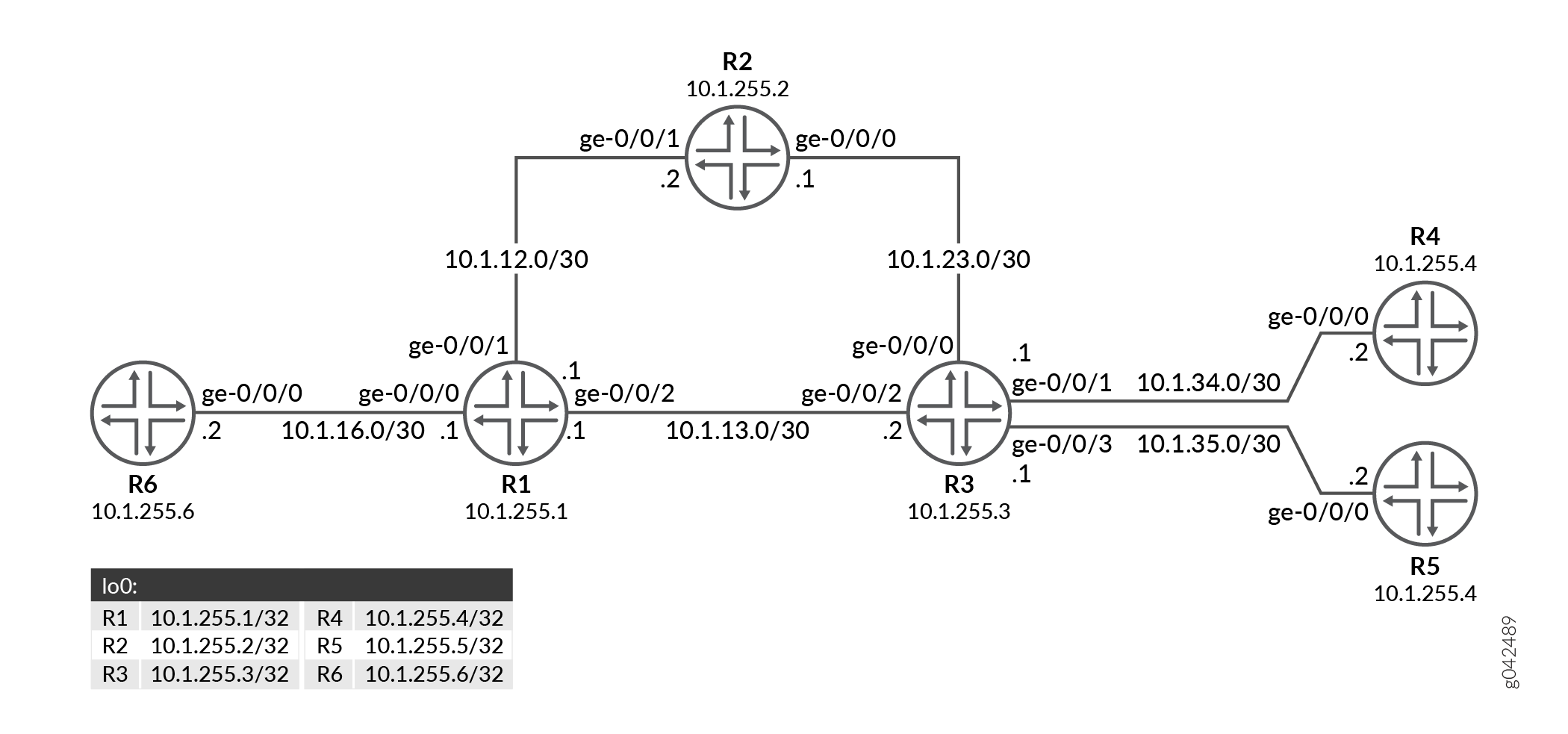
In this example, Router R6 is the root connecting to two leaf nodes, Routers R4 and R5. Router R1 is the point of local repair.
Configuration
CLI Quick Configuration
To quickly configure this example, copy the
following commands, paste them into a text file, remove any line breaks,
change any details necessary to match your network configuration,
copy and paste the commands into the CLI at the [edit] hierarchy
level, and then enter commit from configuration mode.
R1
user@R1# set system host-name R1
user@R1# set interfaces ge-0/0/0 unit 0 family inet address 10.1.16.1/30
user@R1# set interfaces ge-0/0/0 unit 0 family mpls
user@R1# set interfaces ge-0/0/1 unit 0 family inet address 10.1.12.1/30
user@R1# set interfaces ge-0/0/1 unit 0 family mpls
user@R1# set interfaces ge-0/0/2 unit 0 family inet address 10.1.13.1/30
user@R1# set interfaces ge-0/0/2 unit 0 family mpls
user@R1# set interfaces lo0 unit 0 family inet address 10.1.255.1/32
user@R1# set routing-options router-id 10.1.255.1
user@R1# set routing-options autonomous-system 65001
user@R1# set protocols ldp interface all link-protection dynamic-rsvp-lsp
user@R1# set protocols ldp interface fxp0.0 disable
user@R1# set protocols ldp p2mp
user@R1# set protocols mpls interface all
user@R1# set protocols mpls interface fxp0.0 disable
user@R1# set protocols ospf traffic-engineering
user@R1# set protocols ospf area 0.0.0.0 interface all
user@R1# set protocols ospf area 0.0.0.0 interface fxp0.0 disable
user@R1# set protocols rsvp interface all
user@R1# set protocols rsvp interface fxp0.0 disable
R2
user@R2# set system host-name R2
user@R2# set interfaces ge-0/0/0 unit 0 family inet address 10.1.23.1/30
user@R2# set interfaces ge-0/0/0 unit 0 family mpls
user@R2# set interfaces ge-0/0/1 unit 0 family inet address 10.1.12.2/30
user@R2# set interfaces ge-0/0/1 unit 0 family mpls
user@R2# set interfaces lo0 unit 0 family inet address 10.1.255.2/32
user@R2# set routing-options router-id 10.1.255.2
user@R2# set routing-options autonomous-system 65001
user@R2# set protocols ldp interface all link-protection dynamic-rsvp-lsp
user@R2# set protocols ldp interface fxp0.0 disable
user@R2# set protocols ldp p2mp
user@R2# set protocols mpls interface all
user@R2# set protocols mpls interface fxp0.0 disable
user@R2# set protocols ospf traffic-engineering
user@R2# set protocols ospf area 0.0.0.0 interface all
user@R2# set protocols ospf area 0.0.0.0 interface fxp0.0 disable
user@R2# set protocols rsvp interface all
user@R2# set protocols rsvp interface fxp0.0 disable
R3
user@R3# set system host-name R3
user@R3# set interfaces ge-0/0/0 unit 0 family inet address 10.1.23.2/30
user@R3# set interfaces ge-0/0/0 unit 0 family mpls
user@R3# set interfaces ge-0/0/1 unit 0 family inet address 10.1.34.1/30
user@R3# set interfaces ge-0/0/1 unit 0 family mpls
user@R3# set interfaces ge-0/0/2 unit 0 family inet address 10.1.13.2/30
user@R3# set interfaces ge-0/0/2 unit 0 family mpls
user@R3# set interfaces ge-0/0/3 unit 0 family inet address 10.1.35.1/30
user@R3# set interfaces ge-0/0/3 unit 0 family mpls
user@R3# set interfaces lo0 unit 0 family inet address 10.1.255.3/32
user@R3# set routing-options router-id 10.1.255.3
user@R3# set routing-options autonomous-system 65001
user@R3# set protocols ldp interface all link-protection dynamic-rsvp-lsp
user@R3# set protocols ldp interface fxp0.0 disable
user@R3# set protocols ldp p2mp
user@R3# set protocols mpls interface all
user@R3# set protocols mpls interface fxp0.0 disable
user@R3# set protocols ospf traffic-engineering
user@R3# set protocols ospf area 0.0.0.0 interface all
user@R3# set protocols ospf area 0.0.0.0 interface fxp0.0 disable
user@R3# set protocols rsvp interface all
user@R3# set protocols rsvp interface fxp0.0 disable
R4
user@R4# set system host-name R4
user@R4# set interfaces ge-0/0/0 unit 0 family inet address 10.1.34.2/30
user@R4# set interfaces ge-0/0/0 unit 0 family mpls
user@R4# set interfaces lo0 unit 0 family inet address 10.1.255.4/32
user@R4# set routing-options router-id 10.1.255.4
user@R4# set routing-options autonomous-system 65001
user@R4# set protocols ldp interface all link-protection dynamic-rsvp-lsp
user@R4# set protocols ldp interface fxp0.0 disable
user@R4# set protocols ldp p2mp root-address 10.1.255.6 lsp-id 1
user@R4# set protocols mpls interface all
user@R4# set protocols mpls interface fxp0.0 disable
user@R4# set protocols ospf traffic-engineering
user@R4# set protocols ospf area 0.0.0.0 interface all
user@R4# set protocols ospf area 0.0.0.0 interface fxp0.0 disable
user@R4# set protocols rsvp interface all
user@R4# set protocols rsvp interface fxp0.0 disable
R5
user@R5# set system host-name R5
user@R5# set interfaces ge-0/0/0 unit 0 family inet address 10.1.35.2/30
user@R5# set interfaces ge-0/0/0 unit 0 family mpls
user@R5# set interfaces lo0 unit 0 family inet address 10.1.255.5/32
user@R5# set routing-options router-id 10.1.255.5
user@R5# set routing-options autonomous-system 65001
user@R5# set protocols ldp interface all link-protection dynamic-rsvp-lsp
user@R5# set protocols ldp interface fxp0.0 disable
user@R5# set protocols ldp p2mp root-address 10.1.255.6 lsp-id 1
user@R5# set protocols mpls interface all
user@R5# set protocols mpls interface fxp0.0 disable
user@R5# set protocols ospf traffic-engineering
user@R5# set protocols ospf area 0.0.0.0 interface all
user@R5# set protocols ospf area 0.0.0.0 interface fxp0.0 disable
user@R5# set protocols rsvp interface all
user@R5# set protocols rsvp interface fxp0.0 disable
R6
user@R6# set system host-name R6
user@R6# set interfaces ge-0/0/0 unit 0 family inet address 10.1.16.2/30
user@R6# set interfaces ge-0/0/0 unit 0 family mpls
user@R6# set interfaces lo0 unit 0 family inet address 10.1.255.6/32
user@R6# set routing-options router-id 10.1.255.6
user@R6# set routing-options autonomous-system 65001
user@R6# set protocols ldp interface all link-protection dynamic-rsvp-lsp
user@R6# set protocols ldp interface fxp0.0 disable
user@R6# set protocols ldp p2mp
user@R6# set protocols mpls interface all
user@R6# set protocols mpls interface fxp0.0 disable
user@R6# set protocols ospf traffic-engineering
user@R6# set protocols ospf area 0.0.0.0 interface all
user@R6# set protocols ospf area 0.0.0.0 interface fxp0.0 disable
user@R6# set protocols rsvp interface all
user@R6# set protocols rsvp interface fxp0.0 disable
Procedure
- Configuring Device R1 Step-by-Step Procedure
- Configuring Device R2 Step-by-Step Procedure
- Configuring Device R3 Step-by-Step Procedure
- Configuring Device R4 Step-by-Step Procedure
- Configuring Device R5 Step-by-Step Procedure
- Configuring Device R6 Step-by-Step Procedure
Configuring Device R1 Step-by-Step Procedure
The following example requires you to navigate various levels in the configuration hierarchy. For information about navigating the CLI, see Using the CLI Editor in Configuration Mode.
To configure Router R1:
Set the system hostname.
[edit]
user@R1# set system host-name R1
-
Configure the Router R1 interfaces.
[edit]
user@R1# set interfaces ge-0/0/0 unit 0 family inet address 10.1.16.1/30
user@R1# set interfaces ge-0/0/0 unit 0 family mpls
user@R1# set interfaces ge-0/0/1 unit 0 family inet address 10.1.12.1/30
user@R1# set interfaces ge-0/0/1 unit 0 family mpls
user@R1# set interfaces ge-0/0/2 unit 0 family inet address 10.1.13.1/30
user@R1# set interfaces ge-0/0/2 unit 0 family mpls
Assign the loopback addresses to the device.
[edit]
user@R1# set interfaces lo0 unit 0 family inet address 10.1.255.1/32
-
Configure the router ID and autonomous system of Router R1.
[edit]
user@R1# set routing-options router-id 10.1.255.1
user@R1# set routing-options autonomous-system 65001
-
Enable RSVP on all the interfaces (excluding the management interface).
[edit]
user@R1# set protocols rsvp interface all
user@R1# set protocols rsvp interface fxp0.0 disable
-
Enable MPLS on all the interfaces (excluding the management interface).
[edit]
user@R1# set protocols mpls interface all
user@R1# set protocols mpls interface fxp0.0 disable
-
Enable OSPF on all the interfaces (excluding the management interface) and enable traffic engineering capabilities.
[edit]
user@R1# set protocols ospf traffic-engineering
user@R1# set protocols ospf area 0.0.0.0 interface all
user@R1# set protocols ospf area 0.0.0.0 interface fxp0.0 disable
-
Enable LDP on all the interfaces (excluding the management interface) and configure link protection with dynamic RSVP bypass LSP.
[edit]
user@R1# set protocols ldp interface all link-protection dynamic-rsvp-lsp
user@R1# set protocols ldp interface fxp0.0 disable
user@R1# set protocols ldp p2mp
Results
From configuration mode, confirm your configuration by entering the
show configuration command. If the output does
not display the intended configuration, repeat the instructions in
this example to correct the configuration.
user@R1# show configuration
system {
    host-name R1;
}
interfaces {
    ge-0/0/0 {
        unit 0 {
            family inet {
                address 10.1.16.1/30;
            }
            family mpls;
        }
    }
    ge-0/0/1 {
        unit 0 {
            family inet {
                address 10.1.12.1/30;
            }
            family mpls;
        }
    }
    ge-0/0/2 {
        unit 0 {
            family inet {
                address 10.1.13.1/30;
            }
            family mpls;
        }
    }
    lo0 {
        unit 0 {
            family inet {
                address 10.1.255.1/32;
            }
        }
    }
}
routing-options {
    router-id 10.1.255.1;
    autonomous-system 65001;
}
protocols {
    ldp {
        interface all {
            link-protection {
                dynamic-rsvp-lsp;
            }
        }
        interface fxp0.0 {
            disable;
        }
        p2mp;
    }
    mpls {
        interface all;
        interface fxp0.0 {
            disable;
        }
    }
    ospf {
        traffic-engineering;
        area 0.0.0.0 {
            interface all;
            interface fxp0.0 {
                disable;
            }
        }
    }
    rsvp {
        interface all;
        interface fxp0.0 {
            disable;
        }
    }
}
Configuring Device R2 Step-by-Step Procedure
The following example requires you to navigate various levels in the configuration hierarchy. For information about navigating the CLI, see Using the CLI Editor in Configuration Mode.
To configure Router R2:
Set the system hostname.
[edit]
user@R2# set system host-name R2
-
Configure the Router R2 interfaces.
[edit]
user@R2# set interfaces ge-0/0/0 unit 0 family inet address 10.1.23.1/30
user@R2# set interfaces ge-0/0/0 unit 0 family mpls
user@R2# set interfaces ge-0/0/1 unit 0 family inet address 10.1.12.2/30
user@R2# set interfaces ge-0/0/1 unit 0 family mpls
Assign the loopback addresses to the device.
[edit]
user@R2# set interfaces lo0 unit 0 family inet address 10.1.255.2/32
-
Configure the router ID and autonomous system of Router R2.
[edit]
user@R2# set routing-options router-id 10.1.255.2
user@R2# set routing-options autonomous-system 65001
-
Enable RSVP on all the interfaces (excluding the management interface).
[edit]
user@R2# set protocols rsvp interface all
user@R2# set protocols rsvp interface fxp0.0 disable
-
Enable MPLS on all the interfaces (excluding the management interface).
[edit]
user@R2# set protocols mpls interface all
user@R2# set protocols mpls interface fxp0.0 disable
-
Enable OSPF on all the interfaces (excluding the management interface) and enable traffic engineering capabilities.
[edit]
user@R2# set protocols ospf traffic-engineering
user@R2# set protocols ospf area 0.0.0.0 interface all
user@R2# set protocols ospf area 0.0.0.0 interface fxp0.0 disable
-
Enable LDP on all the interfaces (excluding the management interface) and configure link protection with dynamic RSVP bypass LSP.
[edit]
user@R2# set protocols ldp interface all link-protection dynamic-rsvp-lsp
user@R2# set protocols ldp interface fxp0.0 disable
user@R2# set protocols ldp p2mp
Results
From configuration mode, confirm your configuration by entering the
show configuration command. If the output does
not display the intended configuration, repeat the instructions in
this example to correct the configuration.
user@R2# show configuration
system {
    host-name R2;
}
interfaces {
    ge-0/0/0 {
        unit 0 {
            family inet {
                address 10.1.23.1/30;
            }
            family mpls;
        }
    }
    ge-0/0/1 {
        unit 0 {
            family inet {
                address 10.1.12.2/30;
            }
            family mpls;
        }
    }
    lo0 {
        unit 0 {
            family inet {
                address 10.1.255.2/32;
            }
        }
    }
}
routing-options {
    router-id 10.1.255.2;
    autonomous-system 65001;
}
protocols {
    ldp {
        interface all {
            link-protection {
                dynamic-rsvp-lsp;
            }
        }
        interface fxp0.0 {
            disable;
        }
        p2mp;
    }
    mpls {
        interface all;
        interface fxp0.0 {
            disable;
        }
    }
    ospf {
        traffic-engineering;
        area 0.0.0.0 {
            interface all;
            interface fxp0.0 {
                disable;
            }
        }
    }
    rsvp {
        interface all;
        interface fxp0.0 {
            disable;
        }
    }
}
Configuring Device R3 Step-by-Step Procedure
The following example requires you to navigate various levels in the configuration hierarchy. For information about navigating the CLI, see Using the CLI Editor in Configuration Mode.
To configure Router R3:
Set the system hostname.
[edit]
user@R3# set system host-name R3
-
Configure the Router R3 interfaces.
[edit]
user@R3# set interfaces ge-0/0/0 unit 0 family inet address 10.1.23.2/30
user@R3# set interfaces ge-0/0/0 unit 0 family mpls
user@R3# set interfaces ge-0/0/1 unit 0 family inet address 10.1.34.1/30
user@R3# set interfaces ge-0/0/1 unit 0 family mpls
user@R3# set interfaces ge-0/0/2 unit 0 family inet address 10.1.13.2/30
user@R3# set interfaces ge-0/0/2 unit 0 family mpls
user@R3# set interfaces ge-0/0/3 unit 0 family inet address 10.1.35.1/30
user@R3# set interfaces ge-0/0/3 unit 0 family mpls
Assign the loopback addresses to the device.
[edit]
user@R3# set interfaces lo0 unit 0 family inet address 10.1.255.3/32
-
Configure the router ID and autonomous system of Router R3.
[edit]
user@R3# set routing-options router-id 10.1.255.3
user@R3# set routing-options autonomous-system 65001
-
Enable RSVP on all the interfaces (excluding the management interface).
[edit]
user@R3# set protocols rsvp interface all
user@R3# set protocols rsvp interface fxp0.0 disable
-
Enable MPLS on all the interfaces (excluding the management interface).
[edit]
user@R3# set protocols mpls interface all
user@R3# set protocols mpls interface fxp0.0 disable
-
Enable OSPF on all the interfaces (excluding the management interface) and enable traffic engineering capabilities.
[edit]
user@R3# set protocols ospf traffic-engineering
user@R3# set protocols ospf area 0.0.0.0 interface all
user@R3# set protocols ospf area 0.0.0.0 interface fxp0.0 disable
-
Enable LDP on all the interfaces (excluding the management interface) and configure link protection with dynamic RSVP bypass LSP.
[edit]
user@R3# set protocols ldp interface all link-protection dynamic-rsvp-lsp
user@R3# set protocols ldp interface fxp0.0 disable
user@R3# set protocols ldp p2mp
Results
From configuration mode, confirm your configuration by entering the
show configuration command. If the output does
not display the intended configuration, repeat the instructions in
this example to correct the configuration.
user@R3# show configuration
system {
    host-name R3;
}
interfaces {
    ge-0/0/0 {
        unit 0 {
            family inet {
                address 10.1.23.2/30;
            }
            family mpls;
        }
    }
    ge-0/0/1 {
        unit 0 {
            family inet {
                address 10.1.34.1/30;
            }
            family mpls;
        }
    }
    ge-0/0/2 {
        unit 0 {
            family inet {
                address 10.1.13.2/30;
            }
            family mpls;
        }
    }
    ge-0/0/3 {
        unit 0 {
            family inet {
                address 10.1.35.1/30;
            }
            family mpls;
        }
    }
    lo0 {
        unit 0 {
            family inet {
                address 10.1.255.3/32;
            }
        }
    }
}
routing-options {
    router-id 10.1.255.3;
    autonomous-system 65001;
}
protocols {
    ldp {
        interface all {
            link-protection {
                dynamic-rsvp-lsp;
            }
        }
        interface fxp0.0 {
            disable;
        }
        p2mp;
    }
    mpls {
        interface all;
        interface fxp0.0 {
            disable;
        }
    }
    ospf {
        traffic-engineering;
        area 0.0.0.0 {
            interface all;
            interface fxp0.0 {
                disable;
            }
        }
    }
    rsvp {
        interface all;
        interface fxp0.0 {
            disable;
        }
    }
}
Configuring Device R4 Step-by-Step Procedure
The following example requires you to navigate various levels in the configuration hierarchy. For information about navigating the CLI, see Using the CLI Editor in Configuration Mode.
To configure Router R4:
Set the system hostname.
[edit]
user@R4# set system host-name R4
-
Configure the Router R4 interfaces.
[edit]
user@R4# set interfaces ge-0/0/0 unit 0 family inet address 10.1.34.2/30
user@R4# set interfaces ge-0/0/0 unit 0 family mpls
Assign the loopback addresses to the device.
[edit]
user@R4# set interfaces lo0 unit 0 family inet address 10.1.255.4/32
-
Configure the router ID and autonomous system of Router R4.
[edit]
user@R4# set routing-options router-id 10.1.255.4
user@R4# set routing-options autonomous-system 65001
-
Enable RSVP on all the interfaces (excluding the management interface).
[edit]
user@R4# set protocols rsvp interface all
user@R4# set protocols rsvp interface fxp0.0 disable
-
Enable MPLS on all the interfaces (excluding the management interface).
[edit]
user@R4# set protocols mpls interface all
user@R4# set protocols mpls interface fxp0.0 disable
-
Enable OSPF on all the interfaces (excluding the management interface) and enable traffic engineering capabilities.
[edit]
user@R4# set protocols ospf traffic-engineering
user@R4# set protocols ospf area 0.0.0.0 interface all
user@R4# set protocols ospf area 0.0.0.0 interface fxp0.0 disable
-
Enable LDP on all the interfaces (excluding the management interface) and configure link protection with dynamic RSVP bypass LSP.
[edit]
user@R4# set protocols ldp interface all link-protection dynamic-rsvp-lsp
user@R4# set protocols ldp interface fxp0.0 disable
user@R4# set protocols ldp p2mp root-address 10.1.255.6 lsp-id 1
Results
From configuration mode, confirm your configuration by entering the
show configuration command. If the output does
not display the intended configuration, repeat the instructions in
this example to correct the configuration.
user@R4# show configuration
system {
    host-name R4;
}
interfaces {
    ge-0/0/0 {
        unit 0 {
            family inet {
                address 10.1.34.2/30;
            }
            family mpls;
        }
    }
    lo0 {
        unit 0 {
            family inet {
                address 10.1.255.4/32;
            }
        }
    }
}
routing-options {
    router-id 10.1.255.4;
    autonomous-system 65001;
}
protocols {
    ldp {
        interface all {
            link-protection {
                dynamic-rsvp-lsp;
            }
        }
        interface fxp0.0 {
            disable;
        }
        p2mp {
            root-address 10.1.255.6 {
                lsp-id 1;
            }
        }
    }
    mpls {
        interface all;
        interface fxp0.0 {
            disable;
        }
    }
    ospf {
        traffic-engineering;
        area 0.0.0.0 {
            interface all;
            interface fxp0.0 {
                disable;
            }
        }
    }
    rsvp {
        interface all;
        interface fxp0.0 {
            disable;
        }
    }
}
Configuring Device R5 Step-by-Step Procedure
The following example requires you to navigate various levels in the configuration hierarchy. For information about navigating the CLI, see Using the CLI Editor in Configuration Mode.
To configure Router R5:
Set the system hostname.
[edit]
user@R5# set system host-name R5
-
Configure the Router R5 interfaces.
[edit]
user@R5# set interfaces ge-0/0/0 unit 0 family inet address 10.1.35.2/30
user@R5# set interfaces ge-0/0/0 unit 0 family mpls
Assign the loopback addresses to the device.
[edit]
user@R5# set interfaces lo0 unit 0 family inet address 10.1.255.5/32
-
Configure the router ID and autonomous system of Router R5.
[edit]
user@R5# set routing-options router-id 10.1.255.5
user@R5# set routing-options autonomous-system 65001
-
Enable RSVP on all the interfaces (excluding the management interface).
[edit]
user@R5# set protocols rsvp interface all
user@R5# set protocols rsvp interface fxp0.0 disable
-
Enable MPLS on all the interfaces (excluding the management interface).
[edit]
user@R5# set protocols mpls interface all
user@R5# set protocols mpls interface fxp0.0 disable
-
Enable OSPF on all the interfaces (excluding the management interface) and enable traffic engineering capabilities.
[edit]
user@R5# set protocols ospf traffic-engineering
user@R5# set protocols ospf area 0.0.0.0 interface all
user@R5# set protocols ospf area 0.0.0.0 interface fxp0.0 disable
-
Enable LDP on all the interfaces (excluding the management interface) and configure link protection with dynamic RSVP bypass LSP.
[edit]
user@R5# set protocols ldp interface all link-protection dynamic-rsvp-lsp
user@R5# set protocols ldp interface fxp0.0 disable
user@R5# set protocols ldp p2mp root-address 10.1.255.6 lsp-id 1
Results
From configuration mode, confirm your configuration by entering the
show configuration command. If the output does
not display the intended configuration, repeat the instructions in
this example to correct the configuration.
user@R5# show configuration
system {
    host-name R5;
}
interfaces {
    ge-0/0/0 {
        unit 0 {
            family inet {
                address 10.1.35.2/30;
            }
            family mpls;
        }
    }
    lo0 {
        unit 0 {
            family inet {
                address 10.1.255.5/32;
            }
        }
    }
}
routing-options {
    router-id 10.1.255.5;
    autonomous-system 65001;
}
protocols {
    ldp {
        interface all {
            link-protection {
                dynamic-rsvp-lsp;
            }
        }
        interface fxp0.0 {
            disable;
        }
        p2mp {
            root-address 10.1.255.6 {
                lsp-id 1;
            }
        }
    }
    mpls {
        interface all;
        interface fxp0.0 {
            disable;
        }
    }
    ospf {
        traffic-engineering;
        area 0.0.0.0 {
            interface all;
            interface fxp0.0 {
                disable;
            }
        }
    }
    rsvp {
        interface all;
        interface fxp0.0 {
            disable;
        }
    }
}
Configuring Device R6 Step-by-Step Procedure
The following example requires you to navigate various levels in the configuration hierarchy. For information about navigating the CLI, see Using the CLI Editor in Configuration Mode.
To configure Router R6:
Set the system hostname.
[edit]
user@R6# set system host-name R6
-
Configure the Router R6 interfaces.
[edit]
user@R6# set interfaces ge-0/0/0 unit 0 family inet address 10.1.16.2/30
user@R6# set interfaces ge-0/0/0 unit 0 family mpls
Assign the loopback addresses to the device.
[edit]
user@R6# set interfaces lo0 unit 0 family inet address 10.1.255.6/32
-
Configure the router ID and autonomous system of Router R6.
[edit]
user@R6# set routing-options router-id 10.1.255.6
user@R6# set routing-options autonomous-system 65001
-
Enable RSVP on all the interfaces (excluding the management interface).
[edit]
user@R6# set protocols rsvp interface all
user@R6# set protocols rsvp interface fxp0.0 disable
-
Enable MPLS on all the interfaces (excluding the management interface).
[edit]
user@R6# set protocols mpls interface all
user@R6# set protocols mpls interface fxp0.0 disable
-
Enable OSPF on all the interfaces (excluding the management interface) and enable traffic engineering capabilities.
[edit]
user@R6# set protocols ospf traffic-engineering
user@R6# set protocols ospf area 0.0.0.0 interface all
user@R6# set protocols ospf area 0.0.0.0 interface fxp0.0 disable
-
Enable LDP on all the interfaces (excluding the management interface) and configure link protection with dynamic RSVP bypass LSP.
[edit]
user@R6# set protocols ldp interface all link-protection dynamic-rsvp-lsp
user@R6# set protocols ldp interface fxp0.0 disable
user@R6# set protocols ldp p2mp
Results
From configuration mode, confirm your configuration by entering the
show configuration command. If the output does
not display the intended configuration, repeat the instructions in
this example to correct the configuration.
user@R6# show configuration
system {
    host-name R6;
}
interfaces {
    ge-0/0/0 {
        unit 0 {
            family inet {
                address 10.1.16.2/30;
            }
            family mpls;
        }
    }
    lo0 {
        unit 0 {
            family inet {
                address 10.1.255.6/32;
            }
        }
    }
}
routing-options {
    router-id 10.1.255.6;
    autonomous-system 65001;
}
protocols {
    ldp {
        interface all {
            link-protection {
                dynamic-rsvp-lsp;
            }
        }
        interface fxp0.0 {
            disable;
        }
        p2mp;
    }
    mpls {
        interface all;
        interface fxp0.0 {
            disable;
        }
    }
    ospf {
        traffic-engineering;
        area 0.0.0.0 {
            interface all;
            interface fxp0.0 {
                disable;
            }
        }
    }
    rsvp {
        interface all;
        interface fxp0.0 {
            disable;
        }
    }
}
Verification
Verify that the configuration is working properly.
- Verifying the Bypass RSVP LSP Path
- Verifying Label Operation
- Verifying Multicast Routes
- Verifying LDP point-to-multipoint tunnel
- Verifying Multicast Routes
Verifying the Bypass RSVP LSP Path
Purpose
Verify that the bypass RSVP LSP path has been created on the point of local repair (PLR).
Action
From operational mode, run the show route tale
mpls.0 command.
user@R1> show route tale mpls.0
mpls.0: 17 destinations, 17 routes (17 active, 0 holddown, 0 hidden)
+ = Active Route, - = Last Active, * = Both

0                  *[MPLS/0] 1d 19:16:27, metric 1
                       Receive
1                  *[MPLS/0] 1d 19:16:27, metric 1
                       Receive
2                  *[MPLS/0] 1d 19:16:27, metric 1
                       Receive
13                 *[MPLS/0] 1d 19:16:27, metric 1
                       Receive
299776             *[LDP/9] 21:57:32, metric 1
                    >  to 10.1.12.2 via ge-0/0/1.0, Pop
                       to 10.1.13.2 via ge-0/0/2.0, label-switched-path ge-0/0/1.0:BypassLSP->10.1.255.2
299776(S=0)        *[LDP/9] 21:57:32, metric 1
                    >  to 10.1.12.2 via ge-0/0/1.0, Pop
                       to 10.1.13.2 via ge-0/0/2.0, label-switched-path ge-0/0/1.0:BypassLSP->10.1.255.2
299792             *[LDP/9] 21:57:32, metric 1
                    >  to 10.1.13.2 via ge-0/0/2.0, Pop
                       to 10.1.12.2 via ge-0/0/1.0, label-switched-path ge-0/0/2.0:BypassLSP->10.1.255.3
299792(S=0)        *[LDP/9] 21:57:32, metric 1
                    >  to 10.1.13.2 via ge-0/0/2.0, Pop
                       to 10.1.12.2 via ge-0/0/1.0, label-switched-path ge-0/0/2.0:BypassLSP->10.1.255.3
299936             *[RSVP/7/1] 1d 16:10:46, metric 1
                    >  to 10.1.12.2 via ge-0/0/1.0, label-switched-path ge-0/0/0.0:BypassLSP->10.1.255.2
299936(S=0)        *[RSVP/7/1] 1d 16:10:46, metric 1
                    >  to 10.1.12.2 via ge-0/0/1.0, label-switched-path ge-0/0/0.0:BypassLSP->10.1.255.2
299968             *[LDP/9] 21:01:04, metric 1
                    >  to 10.1.16.2 via ge-0/0/0.0, Pop
299968(S=0)        *[LDP/9] 21:01:04, metric 1
                    >  to 10.1.16.2 via ge-0/0/0.0, Pop
300000             *[LDP/9] 20:41:55, metric 1
                    >  to 10.1.13.2 via ge-0/0/2.0, Swap 299984
                       to 10.1.12.2 via ge-0/0/1.0, label-switched-path ge-0/0/2.0:BypassLSP->10.1.255.3
300016             *[LDP/9] 20:41:55, metric 1
                    >  to 10.1.13.2 via ge-0/0/2.0, Swap 300000
                       to 10.1.12.2 via ge-0/0/1.0, label-switched-path ge-0/0/2.0:BypassLSP->10.1.255.3
300032             *[LDP/9] 20:41:55, metric 1
                    >  to 10.1.13.2 via ge-0/0/2.0, Swap 300016
                       to 10.1.12.2 via ge-0/0/1.0, label-switched-path ge-0/0/2.0:BypassLSP->10.1.255.3
300048             *[RSVP/7/1] 00:02:43, metric 1
                    >  to 10.1.13.2 via ge-0/0/2.0, label-switched-path ge-0/0/0.0:BypassLSP->10.1.255.3
300048(S=0)        *[RSVP/7/1] 00:02:43, metric 1
                    >  to 10.1.13.2 via ge-0/0/2.0, label-switched-path ge-0/0/0.0:BypassLSP->10.1.255.3
Meaning
When the R1-R3 link goes down, the RSVP bypass LSP is used to route traffic.
Verifying Label Operation
Purpose
Verify the label swapping at the PLR.
Action
From operational mode, run the show route table
mpls.0 label label extensive command.
user@R1> show route table mpls.0 label 300000 extensive
mpls.0: 17 destinations, 17 routes (17 active, 0 holddown, 0 hidden)
300000 (1 entry, 1 announced)
TSI:
KRT in-kernel 300000 /52 -> {Swap 299984}
        *LDP    Preference: 9
                Next hop type: Router, Next hop index: 0
                Address: 0x872dab4
                Next-hop reference count: 1, Next-hop session id: 0
                Kernel Table Id: 0
                Next hop: 10.1.13.2 via ge-0/0/2.0 weight 0x1, selected
                Label operation: Swap 299984
                Load balance label: Label 299984: None;
                Label element ptr: 0x1740a600
                Label parent element ptr: 0x0
                Label element references: 2
                Label element child references: 0
                Label element lsp id: 0
                Session Id: 0
                Next hop: 10.1.12.2 via ge-0/0/1.0 weight 0x8000
                Label-switched-path ge-0/0/2.0:BypassLSP->10.1.255.3
                Label operation: Swap 299984, Push 299936(top)
                Label TTL action: prop-ttl, prop-ttl(top)
                Load balance label: Label 299984: None; Label 299936: None;
                Label element ptr: 0x17409750
                Label parent element ptr: 0x1740b190
                Label element references: 1
                Label element child references: 0
                Label element lsp id: 9
                Session Id: 0
                State: <Active Int NhAckRequest>
                Local AS: 65001
                Age: 20:42:01   Metric: 1
                Validation State: unverified
                Task: LDP
                Announcement bits (1): 1-KRT
                AS path: I
                Prefixes bound to route: 10.1.255.4/32
                Thread: junos-main
Meaning
The label is bound to reach Router R5, which is a leaf node.
Verifying Multicast Routes
Purpose
Verify the IP multicast forwarding table to make sure that there is an upstream RPF interface list, with a primary and a backup interface.
Action
From operational mode, run the show ldp p2mp path command.
user@R1> show ldp p2mp path
P2MP path type: Transit/Egress
  Output Session (label): 10.1.255.6:0 (300016) (Primary)
  Input Session (label): 10.1.255.3:0 (300000)
  Attached FECs:  P2MP root-addr 10.1.255.6, lsp-id 1 (Active)
Meaning
The output shows primary sessions.
Verifying LDP point-to-multipoint tunnel
Purpose
Verify the LDP point-to-multipoint tunnel table information.
Action
From operational mode, run the show ldp p2mp tunnel command.
user@R6> show ldp p2mp tunnel
Instance    Tunnel type          Tunnel name
0           Name              ldp-p2mp:static:10.1.255.6:1:master
    P2MP root-addr 10.1.255.6, lsp-id 1
    Self id 805306420
Meaning
The output shows LDP point-to-multipoint tunnel table information.
Verifying Multicast Routes
Purpose
Verify the IP multicast forwarding table to make sure that there is an upstream RPF interface list, with a primary and a backup interface.
Action
From operational mode, run the show ldp p2mp path command.
user@R6> show ldp p2mp path
P2MP path type: Ingress
  Input Session (label): 10.1.255.1:0 (300016)
  Attached FECs:  P2MP root-addr 10.1.255.6, lsp-id 1 (Active)
Meaning
The output shows primary sessions.