IPv6-over-Ipv4 Tunnels
Configuring IPv6 Tunneling for MPLS
You can configure the IPv6 tunneling for MPLS to tunnel IPv6 traffic over an MPLS-based IPv4 network. This configuration allows you to interconnect a number of smaller IPv6 networks over an IPv4-based network core, giving you the ability to provide IPv6 service without having to upgrade the switches in your core network. BGP is configured to exchange routes between the IPv6 networks, and data is tunneled between these IPv6 networks by means of IPv4-based MPLS.
To configure IPv6 tunneling for MPLS on your EX Series switch:
Example: Tunneling IPv6 Traffic over MPLS IPv4 Networks
This example shows how to configure the Junos OS to tunnel IPv6 over an MPLS-based IPv4 network. External BGP (EBGP) is used between the customer edge (CE) and provider edge (PE) devices. The remote CE devices have different AS numbers for loop detection.
Requirements
No special configuration beyond device initialization is required before you configure this example.
Overview
Detailed information about the Juniper Networks implementation of IPv6 over MPLS is described in the following Internet drafts:
-
Internet draft draft-ietf-l3vpn-bgp-ipv6-07.txt, BGP-MPLS IP VPN extension for IPv6 VPN (expires January 2006)
-
Internet draft draft-ooms-v6ops-bgp-tunnel-06.txt, Connecting IPv6 Islands over IPv4 MPLS using IPv6 Provider Edge Routers (expires July 2006)
These Internet drafts are available on the IETF website at http://www.ietf.org/.
This example shows you how to interconnect a two IPv6 networks over an IPv4-based network core, giving you the ability to provide IPv6 service without having to upgrade the routers in your core network. Multiprotocol Border Gateway Protocol (MP-BGP) is configured to exchange routes between the IPv6 networks, and data is tunneled between these IPv6 networks by means of IPv4-based MPLS.
In Figure 1, Routers PE1 and PE2 are dual-stack BGP routers, meaning they have both IPv4 and IPv6 stacks. The PE routers link the IPv6 networks through the customer edge (CE) routers to the IPv4 core network. The CE routers and the PE routers connect through a link layer that can carry IPv6 traffic. The PE routers use IPv6 on the CE router-facing interfaces and use IPv4 and MPLS on the core-facing interfaces. Note that one of the connected IPv6 networks could be the global IPv6 Internet.
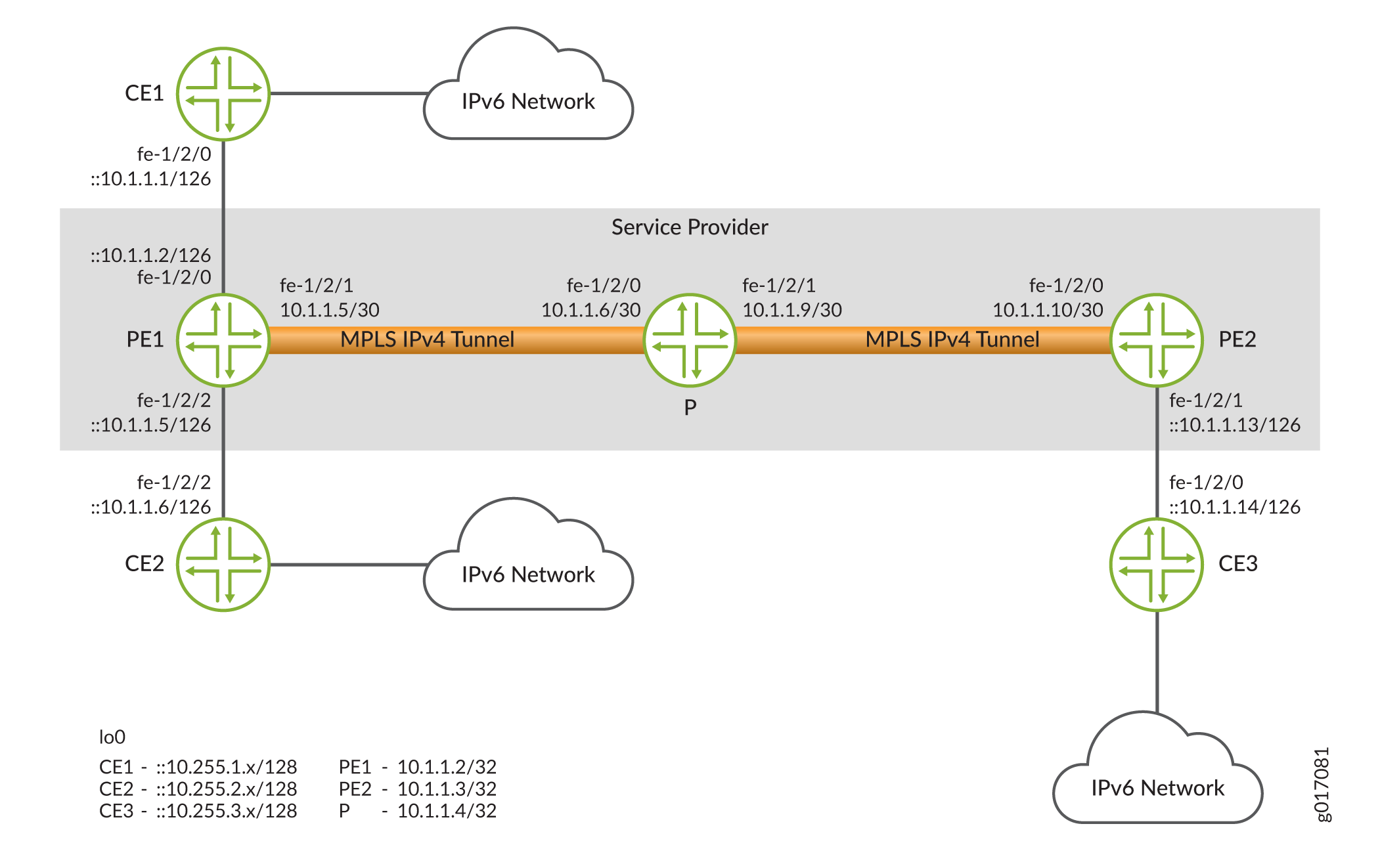
The two PE routers are linked through an MP-BGP session using IPv4 addresses. They use the session to exchange IPv6 routes with an IPv6 (value 2) address family indicator (AFI) and a subsequent AFI (SAFI) (value 4). Each PE router sets the next hop for the IPv6 routes advertised on this session to its own IPv4 address. Because MP-BGP requires the BGP next hop to correspond to the same address family as the network layer reachability information (NLRI), this IPv4 address needs to be embedded within an IPv6 format.
The PE routers can learn the IPv6 routes from the CE routers connected to them using routing protocols Routing Information Protocol next generation (RIPng) or MP-BGP, or through static configuration. Note that if BGP is used as the PE-router-to-CE-router protocol, the MP-BGP session between the PE router and CE router could occur over an IPv4 or IPv6 Transmission Control Protocol (TCP) session. Also, the BGP routes exchanged on that session would have SAFI unicast. You must configure an export policy to pass routes between IBGP and EBGP, and between BGP and any other protocol.
The PE routers have MPLS LSPs routed to each others’ IPv4 addresses. IPv4 provides signaling for the LSPs by means of either LDP or RSVP. These LSPs are used to resolve the next-hop addresses of the IPv6 routes learned from MP-BGP. The next hops use IPv4-mapped IPv6 addresses, while the LSPs use IPv4 addresses.
The PE routers always advertise IPv6 routes to each other using a label value of 2, the explicit null label for IPv6 as defined in RFC 3032, MPLS Label Stack Encoding. As a consequence, each of the forwarding next hops for the IPv6 routes learned from remote PE routers normally push two labels. The inner label is 2 (this label could be different if the advertising PE router is not a Juniper Networks routing platform), and the outer label is the LSP label. If the LSP is a single-hop LSP, then only Label 2 is pushed.
It is also possible for the PE routers to exchange plain IPv6 routes using SAFI unicast. However, there is one major advantage in exchanging labeled IPv6 routes. The penultimate-hop router for an MPLS LSP can pop the outer label and then send the packet with the inner label as an MPLS packet. Without the inner label, the penultimate-hop router would need to discover whether the packet is an IPv4 or IPv6 packet to set the protocol field in the Layer 2 header correctly.
When the PE1 router in Figure 1 receives an IPv6 packet from the CE1 router, it performs a lookup in the IPv6 forwarding table. If the destination matches a prefix learned from the CE2 router, then no labels need to be pushed and the packet is simply sent to the CE2 router. If the destination matches a prefix that was learned from the PE2 router, then the PE1 router pushes two labels onto the packet and sends it to the provider router. The inner label is 2 and the outer label is the LSP label for the PE2 router.
Each provider router in the service provider’s network handles the packet as it would any MPLS packet, swapping labels as it passes from provider router to provider router. The penultimate-hop provider router for the LSP pops the outer label and sends the packet to the PE2 router. When the PE2 router receives the packet, it recognizes the IPv6 explicit null label on the packet (Label 2). It pops this label and treats it as an IPv6 packet, performing a lookup in the IPv6 forwarding table and forwarding the packet to the CE3 router.
This example includes the following settings:
-
In addition to configuring the
family inet6statement on all the CE router–facing interfaces, you must also configure the statement on all the core-facing interfaces running MPLS. Both configurations are necessary because the router must be able to process any IPv6 packets it receives on these interfaces. You should not see any regular IPv6 traffic arrive on these interfaces, but you will receive MPLS packets tagged with Label 2. Even though Label 2 MPLS packets are sent in IPv4, these packets are treated as native IPv6 packets. -
You enable IPv6 tunneling by including the
ipv6-tunnelingstatement in the configuration for the PE routers. This statement allows IPv6 routes to be resolved over an MPLS network by converting all routes stored in the inet.3 routing table to IPv4-mapped IPv6 addresses and then copying them into the inet6.3 routing table. This routing table can be used to resolve next hops for both inet6 and inet6-vpn routes.Note:BGP automatically runs its import policy even when copying routes from a primary routing table group to a secondary routing table group. If IPv4 labeled routes arrive from a BGP session (for example, when you have configured the
labeled-unicaststatement at the[edit protocols bgp family inet]hierarchy level on the PE router), the BGP neighbor’s import policy also accepts IPv6 routes, since the neighbor’s import policy is run while doing the copy operation to the inet6.3 routing table. -
When you configure MP-BGP to carry IPv6 traffic, the IPv4 MPLS label is removed at the destination PE router. The remaining IPv6 packet without a label can then be forwarded to the IPv6 network. To enable this, include the
explicit-nullstatement in the BGP configuration.
Configuration
CLI Quick Configuration
To quickly configure this example, copy the following commands, paste them into a
text file, remove any line breaks, change any details necessary to match your
network configuration, and then copy and paste the commands into the CLI at the
[edit] hierarchy level.
Device PE1
set interfaces fe-1/2/0 unit 0 family inet6 address ::10.1.1.2/126
set interfaces fe-1/2/0 unit 0 family mpls
set interfaces fe-1/2/1 unit 0 family inet address 10.1.1.5/30
set interfaces fe-1/2/1 unit 0 family inet6
set interfaces fe-1/2/1 unit 0 family mpls
set interfaces lo0 unit 0 family inet address 10.1.1.2/32
set protocols mpls ipv6-tunneling
set protocols mpls interface fe-1/2/0.0
set protocols mpls interface fe-1/2/1.0
set protocols bgp group toCE1 type external
set protocols bgp group toCE1 local-address ::10.1.1.2
set protocols bgp group toCE1 family inet6 unicast
set protocols bgp group toCE1 export send-bgp6
set protocols bgp group toCE1 peer-as 65001
set protocols bgp group toCE1 neighbor ::10.1.1.1
set protocols bgp group toPE2 type internal
set protocols bgp group toPE2 local-address 10.1.1.2
set protocols bgp group toPE2 family inet6 labeled-unicast explicit-null
set protocols bgp group toPE2 export next-hop-self
set protocols bgp group toPE2 export send-v6
set protocols bgp group toPE2 neighbor 10.1.1.4
set protocols ospf area 0.0.0.0 interface fe-1/2/1.0
set protocols ospf area 0.0.0.0 interface lo0.0 passive
set protocols ldp interface fe-1/2/1.0
set policy-options policy-statement next-hop-self then next-hop self
set policy-options policy-statement send-bgp6 from family inet6
set policy-options policy-statement send-bgp6 from protocol bgp
set policy-options policy-statement send-bgp6 then accept
set policy-options policy-statement send-v6 from family inet6
set policy-options policy-statement send-v6 from protocol bgp
set policy-options policy-statement send-v6 from protocol direct
set policy-options policy-statement send-v6 then accept
set routing-options router-id 10.1.1.2
set routing-options autonomous-system 65002
Device PE2
set interfaces fe-1/2/0 unit 0 family inet address 10.1.1.10/30
set interfaces fe-1/2/0 unit 0 family inet6
set interfaces fe-1/2/0 unit 0 family mpls
set interfaces fe-1/2/1 unit 0 family inet6 address ::10.1.1.13/126
set interfaces fe-1/2/1 unit 0 family mpls
set interfaces lo0 unit 0 family inet address 10.1.1.4/32
set protocols mpls ipv6-tunneling
set protocols mpls interface fe-1/2/0.0
set protocols mpls interface fe-1/2/1.0
set protocols bgp group toPE1 type internal
set protocols bgp group toPE1 local-address 10.1.1.4
set protocols bgp group toPE1 family inet6 labeled-unicast explicit-null
set protocols bgp group toPE1 export next-hop-self
set protocols bgp group toPE1 export send-v6
set protocols bgp group toPE1 neighbor 10.1.1.2
set protocols bgp group toCE3 type external
set protocols bgp group toCE3 local-address ::10.1.1.13
set protocols bgp group toCE3 family inet6 unicast
set protocols bgp group toCE3 export send-bgp6
set protocols bgp group toCE3 peer-as 65003
set protocols bgp group toCE3 neighbor ::10.1.1.14
set protocols ospf area 0.0.0.0 interface fe-1/2/0.0
set protocols ospf area 0.0.0.0 interface lo0.0 passive
set protocols ldp interface fe-1/2/0.0
set policy-options policy-statement next-hop-self then next-hop self
set policy-options policy-statement send-bgp6 from family inet6
set policy-options policy-statement send-bgp6 from protocol bgp
set policy-options policy-statement send-bgp6 then accept
set policy-options policy-statement send-v6 from family inet6
set policy-options policy-statement send-v6 from protocol bgp
set policy-options policy-statement send-v6 from protocol direct
set policy-options policy-statement send-v6 then accept
set routing-options router-id 10.1.1.4
set routing-options autonomous-system 65002
Device P
set interfaces fe-1/2/0 unit 0 family inet address 10.1.1.6/30
set interfaces fe-1/2/0 unit 0 family inet6
set interfaces fe-1/2/0 unit 0 family mpls
set interfaces fe-1/2/1 unit 0 family inet address 10.1.1.9/30
set interfaces fe-1/2/1 unit 0 family inet6
set interfaces fe-1/2/1 unit 0 family mpls
set interfaces lo0 unit 0 family inet address 10.1.1.3/32
set protocols mpls interface fe-1/2/0.0
set protocols mpls interface fe-1/2/1.0
set protocols ospf area 0.0.0.0 interface fe-1/2/0.0
set protocols ospf area 0.0.0.0 interface fe-1/2/1.0
set protocols ospf area 0.0.0.0 interface lo0.0 passive
set protocols ldp interface fe-1/2/0.0
set protocols ldp interface fe-1/2/1.0
set routing-options router-id 10.1.1.3
set routing-options autonomous-system 65002
Device CE1
set interfaces fe-1/2/0 unit 0 family inet6 address ::10.1.1.1/126
set interfaces lo0 unit 0 family inet6 address ::10.255.1.1/128
set protocols bgp group toPE1 type external
set protocols bgp group toPE1 local-address ::10.1.1.1
set protocols bgp group toPE1 family inet6 unicast
set protocols bgp group toPE1 export send-v6
set protocols bgp group toPE1 peer-as 65002
set protocols bgp group toPE1 neighbor ::10.1.1.2
set policy-options policy-statement send-v6 from family inet6
set policy-options policy-statement send-v6 from protocol direct
set policy-options policy-statement send-v6 then accept
set routing-options router-id 10.255.1.1
set routing-options autonomous-system 65001
Device CE3
set interfaces fe-1/2/0 unit 0 family inet6 address ::10.1.1.14/126
set interfaces lo0 unit 0 family inet6 address ::10.255.1.5/128
set protocols bgp group toPE2 type external
set protocols bgp group toPE2 local-address ::10.1.1.14
set protocols bgp group toPE2 family inet6 unicast
set protocols bgp group toPE2 export send-v6
set protocols bgp group toPE2 peer-as 65002
set protocols bgp group toPE2 neighbor ::10.1.1.13
set policy-options policy-statement send-v6 from family inet6
set policy-options policy-statement send-v6 from protocol direct
set policy-options policy-statement send-v6 then accept
set routing-options router-id 10.255.1.5
set routing-options autonomous-system 65003
Configuring Device PE1
Step-by-Step Procedure
The following example requires you to navigate various levels in the configuration hierarchy. For information about navigating the CLI, see Using the CLI Editor in Configuration Mode in the Junos OS CLI User Guide.
To configure Device PE1:
-
Configure the interfaces.
[edit interfaces]
user@PE1# set fe-1/2/0 unit 0 family inet6 address ::10.1.1.2/126
user@PE1# set fe-1/2/0 unit 0 family mpls
user@PE1# set fe-1/2/1 unit 0 family inet address 10.1.1.5/30
user@PE1# set fe-1/2/1 unit 0 family inet6
user@PE1# set fe-1/2/1 unit 0 family mpls
user@PE1# set lo0 unit 0 family inet address 10.1.1.2/32
-
Configure MPLS on the interfaces.
[edit protocols mpls]
user@PE1# set ipv6-tunneling
user@PE1# set interface fe-1/2/0.0
user@PE1# set interface fe-1/2/1.0
-
Configure BGP.
[edit protocols bgp]
user@PE1# set group toCE1 type external
user@PE1# set group toCE1 local-address ::10.1.1.2
user@PE1# set group toCE1 family inet6 unicast
user@PE1# set group toCE1 export send-bgp6
user@PE1# set group toCE1 peer-as 65001
user@PE1# set group toCE1 neighbor ::10.1.1.1
user@PE1# set group toPE2 type internal
user@PE1# set group toPE2 local-address 10.1.1.2
user@PE1# set group toPE2 family inet6 labeled-unicast explicit-null
user@PE1# set group toPE2 export next-hop-self
user@PE1# set group toPE2 export send-v6
user@PE1# set group toPE2 neighbor 10.1.1.4
-
Configure OSPF
[edit protocols ospf area 0.0.0.0]
user@PE1# set interface fe-1/2/1.0
user@PE1# set interface lo0.0 passive
-
Configure a signaling protocol.
[edit protocols]
user@PE1# set ldp interface fe-1/2/1.0
-
Configure the routing policies.
[edit policy-options]
user@PE1# set policy-statement next-hop-self then next-hop self
user@PE1# set policy-statement send-bgp6 from family inet6
user@PE1# set policy-statement send-bgp6 from protocol bgp
user@PE1# set policy-statement send-bgp6 then accept
user@PE1# set policy-statement send-v6 from family inet6
user@PE1# set policy-statement send-v6 from protocol bgp
user@PE1# set policy-statement send-v6 from protocol direct
user@PE1# set policy-statement send-v6 then accept
-
Configure the router ID and the autonomous system (AS) number.
[edit routing-options]
user@PE1# set router-id 10.1.1.2
user@PE1# set autonomous-system 675002
Results
From configuration mode, confirm your configuration by entering the
show interfaces, show policy-options,
show protocols, and show
routing-options commands. If the output does not display the
intended configuration, repeat the instructions in this example to correct
the configuration.
user@R1# show interfaces
fe-1/2/0 {
    unit 0 {
        family inet6 {
            address ::10.1.1.2/126;
        }
        family mpls;
    }
}
fe-1/2/1 {
    unit 0 {
        family inet {
            address 10.1.1.5/30;
        }
        family inet6;
        family mpls;
    }
}
lo0 {
    unit 0 {
        family inet {
            address 10.1.1.2/32;
        }
    }
}
user@R1# show policy-options
policy-statement next-hop-self {
    then {
        next-hop self;
    }
}
policy-statement send-bgp6 {
    from {
        family inet6;
        protocol bgp;
    }
    then accept;
}
policy-statement send-v6 {
    from {
        family inet6;
        protocol [ bgp direct ];
    }
    then accept;
}
user@R1# show protocols
mpls {
    ipv6-tunneling;
    interface fe-1/2/0.0;
    interface fe-1/2/1.0;
}
bgp {
    group toCE1 {
        type external;
        local-address ::10.1.1.2;
        family inet6 {
            unicast;
        }
        export send-bgp6;
        peer-as 65001;
        neighbor ::10.1.1.1;
    }
    group toPE2 {
        type internal;
        local-address 10.1.1.2;
        family inet6 {
            labeled-unicast {
                explicit-null;
            }
        }
        export [ next-hop-self send-v6 ];
        neighbor 10.1.1.4;
    }
}
ospf {
    area 0.0.0.0 {
        interface fe-1/2/1.0;
        interface lo0.0 {
            passive;
        }
    }
}
ldp {
    interface fe-1/2/1.0;
}
user@R1# show routing-options
router-id 10.1.1.2;
autonomous-system 65002;
If you are done configuring the device, enter commit from
configuration mode. Configure the other devices in the topology, as
shown in CLI Quick Configuration.
Verification
Confirm that the configuration is working properly.
Verifying That the CE Devices Have Connectivity
Purpose
Make sure that the tunnel is operating.
Action
From operational mode, enter the ping command.
user@CE1> ping ::10.1.1.14
PING6(56=40+8+8 bytes) ::10.1.1.1 --> ::10.1.1.14
16 bytes from ::10.1.1.14, icmp_seq=0 hlim=61 time=10.687 ms
16 bytes from ::10.1.1.14, icmp_seq=1 hlim=61 time=9.239 ms
16 bytes from ::10.1.1.14, icmp_seq=2 hlim=61 time=1.842 ms
user@CE3> ping ::10.1.1.1
PING6(56=40+8+8 bytes) ::10.1.1.14 --> ::10.1.1.1
16 bytes from ::10.1.1.1, icmp_seq=0 hlim=61 time=1.484 ms
16 bytes from ::10.1.1.1, icmp_seq=1 hlim=61 time=1.338 ms
16 bytes from ::10.1.1.1, icmp_seq=2 hlim=61 time=1.351 ms
Meaning
The IPv6 CE devices can communicate over the core IPv4 network.