Container LSP Configuration
Dynamic Bandwidth Management Using Container LSP Overview
RSVP LSPs with the autobandwidth feature are increasingly deployed in networks to meet traffic engineering needs. However, the current traffic engineering solutions for point-to-point LSPs are inefficient in terms of network bandwidth utilization, mainly because the ingress routers originating the RSVP LSPs either try to fit the LSPs along a particular path without creating parallel LSPs, or do not interact with the other routers in the network and probe for additional available bandwidth.
This feature provides an ingress router with the capability of acquiring as much network bandwidth as possible by creating parallel LSPs dynamically.
- Understanding RSVP Multipath Extensions
- Junos OS RSVP Multipath Implementation
- Current Traffic Engineering Challenges
- Using Container LSP as a Solution
- Junos OS Container LSP Implementation
- Configuration Statements Supported for Container LSPs
- Impact of Configuring Container LSPs on Network Performance
- Supported and Unsupported Features
Understanding RSVP Multipath Extensions
The RSVP multipath extensions proposed in the IETF [KOMPELLA-MLSP] allow the setup of traffic engineered multipath label-switched paths (container LSPs). The container LSPs, in addition to conforming to traffic engineering constraints, use multiple independent paths from a source to a destination, thereby facilitating load balancing of traffic. The multipath extensions require changes to the RSVP-TE protocol and allow for merging of labels at the downstream nodes (similar to LDP), which also helps in preserving forwarding resources.
The multipath extensions to RSVP provide the following benefits:
Ease of configuration. Typically, multiple RSVP LSPs are configured for either load balancing or bin packing. With a container LSP, there is a single entity to provision, manage, and monitor LSPs. Changes in topology are handled easily and autonomously by the ingress LSP, by adding, changing, or removing member LSPs to rebalance traffic, while maintaining the same traffic engineering constraints.
RSVP equal-cost multipath (ECMP) inherits the standard benefits of ECMP by absorbing traffic surges.
Multipath traffic engineering allows for better and complete usage of network resources.
Knowing the relationship among LSPs helps in computing diverse paths with constraint-based routing. It allows adjustment of member LSPs while other member LSPs continue to carry traffic.
The intermediate routers have an opportunity to merge the labels of member LSPs. This reduces the number of labels that need to get added to the forwarding plane and in turn reduces the convergence time.
If the number of independent ECMP paths is huge, label merging overcomes the platform limitations on maximum (ECMP) next hops. With point-to-point RSVP LSPs that require link or node protection, the next hops are doubled as each LSP is programmed with both primary and backup next hops. RSVP multipath (or ECMP) obviates the need for backup next hops.
When there is a link failure, the router upstream to the link failure can distribute traffic from the failed link to the remaining ECMP branches, obviating the need for bypass LSPs. The bypass LSP approach not only requires more state when signaling backup LSPs, but also suffers from scaling issues that result in merge-point timing out a protected path state block (PSB) before point of local repair (PLR) gets a chance to signal the backup LSP.
Junos OS RSVP Multipath Implementation
In order to deploy RSVP multipath (ECMP) in a network, all the nodes through which ECMP LSPs pass must understand RSVP ECMP protocol extensions. This can be a challenge, especially in a multivendor networks.
Junos OS implements the RSVP multipath extensions without the need for protocol extensions. A single container LSP, which has the characteristics of ECMP and RSVP TE, is provisioned. A container LSP consists of several member LSPs and is set up between the ingress and egress routing device. Each member LSP takes a different path to the same destination. The ingress routing device is configured with all the required parameters to compute the RSVP ECMP LSP. The parameters configured to compute a set of RSVP point-to-point LSPs can be used by the ingress routing device to compute the container LSP as well.
Current Traffic Engineering Challenges
The main challenge for traffic engineering is to cope with the dynamics of both topology and traffic demands. Mechanisms are needed that can handle traffic load dynamics in scenarios with sudden changes in traffic demand and dynamically distribute traffic to benefit form available resources.
Figure 1 illustrates a sample network topology with all the LSPs having the same hold and setup priorities, and admission control restricted on the ingress router. All the links are annotated with a tuple (cost and capacity).
Some of the traffic engineering problems seen in Figure 1 are listed here:
Bin PackingThis problem arises because of a particular order in which LSPs are signaled. The ingress routers might not be able to signal some LSPs with required demands although bandwidth is available in the network, leading to under-utilization of link capacity.
For example, the following LSPs arrive in the sequence mentioned in Table 1.
Table 1: LSP Sequence Order for Bin Packing Time
Source
Destination
Demand
ERO
1
A
E
5
A-C-D-E
2
B
E
10
No ERO
The LSP originating at Router B is not routable as constraint-based routing fails to find a feasible path. However, if Router B is signaled first, both the LSPs are routable. Bin packing happens because of lack of visibility of individual per-LSP, per-device bandwidth demands at the ingress routing device.
Bin packing can also happen when there is no requirement for ordering of LSPs. For example, if there is an LSP with demand X and there are two different paths to the destination from the ingress router with available bandwidths Y1 and Y2, such that Y1 is less than X, Y2 is less than X, and Y1 plus Y2 is greater than or equal to X.
In this case, even though there are enough network resources in terms of available bandwidth to satisfy the aggregate LSP demand X, the LSP might not be signaled or re-optimized with the new demand. In Figure 1, with container LSP support, the ingress B creates two LSPs each of size 5 when demand 10 is posed. One LSP is routed along B-C-E and another one along B-C-D-E.
DeadlockConsidering Figure 1, the LSPs follow the sequence mentioned in Table 2.
Table 2: LSP Sequence Order for Deadlock Time
Source
Destination
Demand
ERO
Event
1
A
E
2
A-C-D-E
Constraint-based routing with RSVP signaling
2
B
E
2
B-C-D-E
Constraint-based routing with RSVP signaling
3
A
E
2 to 20
A-C-D-E
Constraint-based routing fails, no RSVP signaling
At time 3, the demand on LSP from A to E increases from 2 to 20. If autobandwidth is configured, the change does not get detected until the adjustment timer expires. In the absence of admission control at A, the increased traffic demand might cause traffic to drop on other LSPs that share common links with the mis-behaving LSP.
This happens due to the following reasons:
Lack of global state at all the ingress routers
Signaling of mis-behaving demands
Tearing down of mis-behaving demands
With container LSP configured, ingress A has more chances of splitting the load (even incrementally if not fully) across multiple LSPs. So, LSP from A is less likely to see prolonged traffic loss.
Latency InflationLatency inflation is caused by the autobandwidth and other LSPs parameters. Some of the other factors that contribute to latency inflation include:
LSP priority
LSPs choose longer paths because shorter paths between data centers located in the same city can be congested. The bandwidth on the shorter paths can get exhausted by equal or higher priority LSPs. Due to periodic LSP optimization by autobandwidth, LSP can get rerouted to a higher delay path. When many LSPs undergo less than optimal path selection, they can potentially form a chain of dependencies. Modifing the LSP priorities dynamically is a workaround to the issue; however, dynamically adjusting LSP priorities to find shorter paths is a challenging task.
All or Nothing policy
When the demand on an LSP increases and at least one of the links along the shorter path is close to its reservation limit, LSP optimization can force the LSP to move to a longer latency path. LSP has to traverse a long path even though the short path is capable of carrying most of the traffic.
Minimum and maximum bandwidth
Minimum and maximum bandwidth specify the boundaries for LSP sizes. If minimum bandwidth is small, an LSP is more prone to autobandwidth adjustment because a small change in bandwidth is enough to cross the threshold limits. LSPs might reroute although bandwidth is available. On the other hand, if the minimum bandwidth is large, network bandwidth might be wasted. If the maximum bandwidth value is small, a large number of LSPs might be needed at the ingress router to accommodate the application demand. If the maximum bandwidth is large, the LSPs can grow larger in size. Such LSPs can suffer because of an all or nothing policy.
Autobandwidth adjustment threshold
Bandwidth threshold dictates if LSPs need to be re-optimized and resized. If the value is small, LSPs are frequently re-optimized and rerouted. That might cause CPU spike because applications or protocols, such as BGP resolving over the LSPs, might keep the Routing Engine busy doing next-hop resolution. A large value might make an LSP immobile. With container LSP configured, an LSP is less likely to get subjected to one or no policy. An ingress router originates multiple LSPs, although not all LSPs potentially traverse high latency paths.
PredictabilityService providers often want predictable behavior in terms of how LSPs get signaled and routed. Currently, without any global coordination, it is difficult to set up the same set of LSPs in a predictable way. Consider the two different orderings in Table 3 and Table 4. The ERO that an LSP uses depends on its signaling time.
Table 3: LSP Sequence Order for Predictability Time
Source
Destination
Demand
ERO
1
A
E
5
A-C-D-E
2
B
E
5
B-C-E
Table 4: LSP Sequence Order for Predictability Time
Source
Destination
Demand
ERO
1
B
E
5
B-C-E
2
A
E
5
A-C-D-E
Container LSP does not directly help LSPs find predictable EROs. If LSPs are getting rerouted because of an all or no policy without container LSP configured, such LSPs might see less churn if container LSPs are configured, because smaller LSPs have better chances of finding a shorter or same path.
Using Container LSP as a Solution
A container LSP can be used as a solution to the challenges faced by the current traffic engineering features. Considering Figure 1, when the demand X on a container LSP increases with the network capacity (max-flow) being more than the demand, the following approaches come into effect with a container LSP:
- Accommodating the New Demand X
- Creating New LSPs to Meet Demand X
- Assigning Bandwidth to the New LSPs
- Controlling the LSP Paths
Accommodating the New Demand X
In the current implementation, autobandwidth attempts to re-signal an LSP with the new demand X and follows the all or nothing policy as mentioned earlier.
The container LSP approach computes several small (smaller than demand X) bandwidth LSPs such that the aggregate bandwidth is not less than X, and the ingress router performs this adjustment periodically. One of the triggers to create new LSPs or to delete old LSPs can be changed in aggregate bandwidth. The ingress router then load-balances the incoming traffic across the newly created LSPs.
Creating New LSPs to Meet Demand X
Although the number of new LSPs created can be a maximum of the allowed configurable limit, there is not much benefit from these LSPs once the number of LSPs exceeds the number of possible diverse paths or equal-cost multipaths (ECMPs). The benefit of creating the smaller LSPs is seen when an ingress router uses the newly created LSPs for load-balancing traffic. This, however, depends on the network topology and state.
Creating multiple parallel LSPs by all the ingress routers in the network can lead to scaling issues at the transit routers. Thus, the number of new LSPs to be created depends on the size of the individual LSPs and the given aggregate demand, X in this case.
Assigning Bandwidth to the New LSPs
In general, there can be a number of heuristics to allocate bandwidths to the newly created LSPs. An ingress router can solve an optimization problem in which it can maximize a given utility function. The output of an optimization problem is assigning optimal bandwidth values. However, to solve an optimization problem, the number of newly created LSPs has to be fixed. Therefore, it is complex to optimize the number and size of each LSP. Thus, to simplify the problem, the same amount of bandwidth is assumed for all the newly created LSPs, and then the number of required LSPs is computed.
Controlling the LSP Paths
The flexibility to control the LSP paths is expressed in terms of the configuration for point-to-point LSPs and container LSPs. Controlling the LSP paths using the configuration parameters can be applied under two different aspects:
Topology—There are no topology constraints with this feature. Each member LSP is treated like a point-to-point LSP and is re-optimized individually. An ingress router does not try to compute equal IGP cost paths for all its LSPs, but instead it computes paths for all the LSPs using current traffic engineering database information. While computing a path, constraint-based routing adheres to any constraints specified through the configuration, although there is no change in the constraint-based routing method for path computation.
When to create a new LSP—When to create a new LSP can be explicitly specified. By default, an ingress router periodically computes the aggregate traffic rate by adding up the traffic rate of all the individual LSPs. Looking at the aggregate bandwidth and configuration, the ingress router recomputes the number of LSPs and the bandwidths of the LSPs. The new LSPs are then signaled or the existing LSPs are re-signaled with the updated bandwidth. Instead of looking at the instantaneous aggregate rate, the ingress routers can compute an average (of aggregates) over some duration by removing outlier samples (of aggregates). Managing the LSPs that remain outstanding and active by considering aggregate bandwidth is more scalable than creating the new LSPs based on the usage of a particular LSP. The intervals and thresholds can be configured to track the aggregate traffic and trigger adjustment. These dynamic LSPs co-exist and interoperate with per-LSP autobandwidth configuration.
Junos OS Container LSP Implementation
A container LSP is an ECMP TE LSP that acts like a container LSP consisting of one or more member LSPs. A point-to-point TE LSP is equivalent to a container LSP with a single member LSP. Member LSPs are added to the container LSP through a process called splitting, and removed from the container LSP through a process called merging.
- Container LSP Terminology
- LSP Splitting
- LSP Merging
- Node and Link Protection
- Naming Convention
- Normalization
- Constraint-Based Routing Path Computation
- Sampling
- Support for NSR, IPG-FA, and Static Routes
Container LSP Terminology
The following terms are defined in the context of a container LSP:
Normalization—An event occurring periodically when an action is taken to adjust the member LSPs, either to adjust their bandwidths, their number, or both. A normalization process is associated with a sampling process and periodically estimates aggregate utilization of a container LSP.Nominal LSP—The instance of a container LSP that is always present.Supplementary LSP—The instances or sub-LSPs of a container LSP, which are dynamically created or removed.Autobandwidth is run over each of the member LSPs, and each LSP is resized according to the traffic it carries and the autobandwidth configuration parameters. The aggregate demand on a container LSP is tracked by adding up the bandwidth across all the member LSPs.
Minimum signaling-bandwidth—The minimum bandwidth with which a member LSP is signaled at the time of normalization or initialization. This could be different from the minimum-bandwidth defined under autobandwidth.Maximum signaling-bandwidth—The maximum bandwidth with which a member LSP is signaled at the time of normalization or initialization. This could be different from the maximum-bandwidth defined under autobandwidth.Merging-bandwidth—Specifies the lower bandwidth threshold on the aggregate bandwidth usage, such that if the aggregate usage falls below this value, the ingress router merges the member LSPs at the time of normalization.Splitting-bandwidth—Specifies the upper bandwidth threshold on the aggregate bandwidth usage, such that if the aggregate usage exceeds this value, the ingress router splits the member LSPs at the time of normalization.Aggregate minimum-bandwidth—Sum of merging-bandwidth of the current active member LSPs. This minimum bandwidth is different from the autobandwidth minimum-bandwidth.Aggregate maximum-bandwidth—Sum of the splitting-bandwidth of the current active member LSPs. This maximum bandwidth is different from the autobandwidth maximum-bandwidth.
LSP Splitting
Operational Overview
The LSP splitting mechanism enables an ingress router to create new member LSPs or to re-signal existing LSPs with different bandwidths within a container LSP when a demand X is placed on the container LSP. With LSP splitting enabled, an ingress router periodically creates a number of LSPs (by signaling new ones or re-signaling existing ones) to accommodate a new aggregate demand X. In the current implementation, an ingress router tries to find an LSP path satisfying a demand X and other constraints. If no path is found, either the LSP is not signaled or it remains up, but with the old reserved bandwidth.
Between two normalization events (splitting or merging), individual LSPs might get re-signaled with different bandwidths due to the autobandwidth adjustments. If a container LSP is not configured with autobandwidth, then the member LSPs are signaled with the static bandwidth value, if configured. There is no dynamic splitting in this case, as there is no dynamic estimation of aggregate bandwidth. The splitting adjustments with a specific bandwidth value can be manually triggered.
Be aware of the following considerations for LSP splitting:
After LSP splitting, the ingress router continues to inject one forwarding adjacency. Forwarding adjacencies are not supported in IGP for this feature.
Between two normalization events, two LSPs might have different bandwidths subjected to autobandwidth constraints.
After LSPs are split (or merged), make-before-break uses the fixed filter (FF) style sharing unless the
adaptiveoption is configured. However, two different LSPs do not do the shared explicit (SE) style sharing for this feature.When LSPs are re-signaled with modified bandwidths, some of the LSPs might not get signaled successfully, leading to failover options.
Operational Constraints
LSP splitting has the following operational constraints:
LSP bandwidth—Although there are a number of ways to allocate bandwidth values to the LSPs, the Junos OS implementation supports only an equal-bandwidth allocation policy when normalization is done, wherein all the member LSPs are signaled or re-signaled with equal bandwidth.
Number of LSPs—If an ingress router is configured to have a minimum number of LSPs, it maintains the minimum number of LSPs even if the demand can be satisfied with less than the minimum number of LSPs. In case the ingress router is unable to do constraint-based routing for computations on the sufficient number of LSPs or signal sufficient number of LSPs, the ingress router resorts to a number of failback options.
By default, an incremental approach is supported as a fallback option (unless configured differently), where an ingress router makes attempts to bring up the sufficient number of LSPs, such that the new aggregate bandwidth exceeds the old aggregate bandwidth (and is as close to the desired demand as possible). The ingress router then load-balances traffic using the LSPs. The LSPs that could not be brought up are removed by the ingress router.
Supported Criteria
When a container LSP signals a member LSP, the member LSP gets signaled with minimum-signaling-bandwidth. Since each member LSP is configured with autobandwidth, between two normalization events, each LSP can undergo autobandwidth adjustment multiple times. As the traffic demand increases, the ingress router creates additional supplementary LSPs . All member LSPs are used for ECMP, so they should roughly have the same reserved bandwidth after normalization.
For example, if there are K LSPs signaled after normalization, each LSP is signaled with equal bandwidth B. The total aggregate bandwidth reserved is B.K, where B satisfies the following condition:
Minimum signaling-bandwidth is less than or equal to B, which is turn is less than or equal to the maximum signaling-bandwidth
(minimum-signaling-bandwidth ≤ B ≤ maximum-signaling-bandwidth)
Until the next normalization event, each member LSP undergoes several autobandwidth adjustments. After any autobandwidth adjustment, if there are N LSPs with reserved bandwidths bi, where i=1,2,.., N, each bi should satisfy the following the condition:
Minimum bandwidth is less than or equal to bi, which in turn is less than or equal to the maximum bandwidth
(minimum-bandwidth ≤ bi ≤ maximum-bandwidth)
Both the above-mentioned conditions are applicable for per member LSP (nominal and supplementary), and essentially have the reserved bandwidth to exist within a range.
Splitting Triggers
Every time the normalization timer expires, the ingress router decides if LSP splitting is required. The ingress router works with the aggregate bandwidth instead of the individual LSP bandwidths. The following two variables are defined for aggregate bandwidth:
Current-Aggr-Bw—Sum of reserved bandwidths of all current member LSPs.New-Aggr-Bw—Sum of traffic rates on all current member LSPs based on sampling.
Taking for example, if there are N member LSPs in the network at the time of normalization, the two approaches to trigger LSP splitting are as follows:
Absolute trigger—LSP splitting is performed when
New-Aggr-Bwis greater thanAggregate-maximum-bandwidth.(
New-Aggr-Bw>Aggregate-maximum-bandwidth)Relative trigger—Under relative triggering, a dynamic calculation is performed. The
Current-Aggr-Bwis compared withNew-Aggr-Bwat the ingress routing device. LSP splitting is performed when the difference in bandwidth is greater than or equal to a calculated threshold amount. The following equation describes the desired state:([1-a] x
Current-Aggr-Bw<New-Aggr-Bw< [1+a] xCurrent-Aggr-Bw, where 0 </= a </= 1)Note:In the above condition, "a" is the adjustment threshold and its default value is 10 percent (that is, 0.10). You can configure the adjustment threshold using the
splitting-merging-thresholdstatement at the[edit protocols mpls container-label-switched-path lsp-name]hierarchy level. The value is also displayed in theshow mpls container-lsp extensivecommand output.When
New-Aggr-Bwis greater thanCurrent-Aggr-Bwmultiplied by [1+a], thus exceeding the calculated threshold, the ingress routing device does not perform normalization. Instead because this is a relative triggering situation, LSP splitting is performed. However, when both LSP splitting and LSP merging are configured on the ingress router, LSP splitting is triggered on the ingress router when one of the two conditions is satisfied.
LSP Merging
Operational Overview
Junos OS supports two kinds of LSPs – CLI-configured LSPs and dynamically created LSPs. The CLI-configured LSPs are created manually and remain in the system until the configuration is modified. The dynamic LSPs are created dynamically by next generation MVPN, BGP virtual private LAN service (VPLS), or LDP, based on a template configuration, and are removed from the system when not used by any application for a certain duration. LSP merging follows a similar approach as dynamic LSPs.
LSP merging enables an ingress routing device to dynamically eliminate some member LSPs of the container LSP so less state information is maintained in the network. If an ingress router provisions several member LSPs between the ingress and egress routers, and there is an overall reduction in aggregate bandwidth (resulting in some LSPs being under-utilized), the ingress router distributes the new traffic load among fewer LSPs.
Although there are a number of ways to merge the member LSPs, Junos OS supports only overall-merge when normalization is being performed. An ingress router considers the aggregate demand and the minimum (or maximum) number of LSPs and revises the number of LSPs that should be active at an ingress routing device. As a result, the following can take place periodically as the normalization timer fires:
Re-signaling some of the existing LSPs with updated bandwidth
Creating new LSPs
Removing some of the existing LSPs
Operational Constraints
If a container LSP is not configured with autobandwidth, then the member LSPs are signaled with the static bandwidth value, if configured. LSP merging does not happen because there is no dynamic estimation of aggregate bandwidth. However, a manual trigger for splitting and adjusting with a specific bandwidth value can be configured.
Nominal LSPs are never deleted as part of LSP merging.
Before deleting an LSP, the LSP is made inactive, so that traffic shifts to other LSPs before removing the LSP. This is because RSVP sends PathTear before deleting routes and next hops from the Packet Forwarding Engine.
When member LSPs are re-signaled with modified bandwidth, it might happen that some LSPs do not get signaled successfully.
Merging Triggers
Every time the normalization timer expires, the ingress router decides if LSP merging is required. The ingress router works with the aggregate bandwidth instead of the individual LSP bandwidths. The following two variables are defined for aggregate bandwidth:
Current-Aggr-Bw—Sum of reserved bandwidths of all current member LSPs.New-Aggr-Bw—Sum of traffic rates on all current member LSPs based on sampling.
For example, if there are N member LSPs in the network at the time of normalization, the two approaches to trigger LSP merging are as follows:
Absolute trigger—LSP merging is performed when
New-Aggr-Bwis less thanAggregate-minimum-bandwidth.(
New-Aggr-Bw<Aggregate-minimum-bandwidth)Relative trigger—The
Current-Aggr-Bwis compared withNew-Aggr-Bwat the ingress routing device. LSP merging is performed when the difference in the bandwidth amount is off by a threshold.([1-a] x
Current-Aggr-Bw<New-Aggr-Bw< [1+a] xCurrent-Aggr-Bw, where 0 </= a </= 1)Note:In the above condition, "a" is the adjustment threshold and its default value is 10 percent (that is, 0.10). You can configure the adjustment threshold using the
splitting-merging-thresholdstatement at the[edit protocols mpls container-label-switched-path lsp-name]hierarchy level. The value is also displayed in theshow mpls container-lsp extensivecommand output.When the
New-Aggr-Bwvalue is less than or equal to [1+a] multiplied by theCurrent-Aggr-Bwvalue, the ingress routing device does not perform normalization, but instead LSP merging is done. However, when both LSP splitting and LSP merging are configured on the ingress router, LSP splitting is triggered on the ingress router when one of the two conditions is satisfied.
Node and Link Protection
Junos OS supports the following mechanisms for node and link protection:
Fast-reroute
Link protection
Node-link protection
Only one of the above-mentioned modes of protection can be configured on an ingress routing device at any given time. All member LSPs (nominal and supplementary) use the same mode of protection that is configured.
Naming Convention
While configuring a container LSP, a name is assigned to the LSP. The name of a nominal and a supplementary LSP is formed by adding the configured-name suffix and an auto-generated suffix to the name of the container LSP. The name of the container LSP is unique and is checked for accuracy during the configuration parsing. The container LSP name should uniquely identify parameters, such as the ingress and egress router names.
A container LSP member LSP and a point-to-point LSP on an ingress routing device cannot have the same LSP name.
The container LSPs follow a number-based LSP naming convention.
For example, if the nominal LSP's configured name is bob and the number of member LSPs is N, the member LSPs are named bob-<configured-suffix>-1, bob-<configured-suffix>-2, ..., and bob-<configured-suffix>-N.
After a normalization event, the number of member LSPs can change.
For example, if the number of member LSPs increases from six to eight,
then the ingress routing device keeps the first six LSPs named bob-<configured-suffix>-1, bob-<configured-suffix>-2, ..., and bob-<configured-suffix>-6. The two additional LSPs
are named bob-7 and bob-8. The original LSPs
might need to be re-optimized if their signaled bandwidth changes.
Similarly, if the number of member LSPs reduces from eight to
six, the ingress routing device re-signals the member LSPs in such
as a way that the remaining active LSPs in the system are named bob-<configured-suffix>-1, bob-<configured-suffix>-2, ..., and bob-<configured-suffix>-6.
In the process of creating new LSPs, an RSVP LSP named bob-<configured-suffix>-7 can be configured.
Normalization
Operational Overview
Normalization is an event that happens periodically. When it happens, a decision is made on the number of member LSPs that should remain active and their respective bandwidths in a container LSP. More specifically, the decision is made on whether new supplementary LSPs are to be created, or any existing LSPs are required to be re-signaled or deleted during the normalization event.
Between two normalization events, a member LSP can undergo several autobandwidth adjustments. A normalization timer, similar to re-optimization timer, is configured. The normalization timer interval should be no less than the adjustment interval or optimization timer.
Normalization is not triggered based on network events, such as topology changes.
Operational Constraints
Normalization has the following operational constraints:
Normalization happens only when none of the member LSPs are undergoing re-optimization or make-before-break. Normalization starts when all the member LSPs complete their ongoing make-before-break. If normalization is pending, new optimization should not be attempted until the normalization is complete.
After normalization, an ingress routing device first computes a set of bandwidth-feasible paths using constraint-based routing computations. If enough constraint-based routing computed paths are not brought up with an aggregate bandwidth value that exceeds the desired bandwidth, several failover actions are taken.
After a set of bandwidth-feasible paths are available, the ingress routing device signals those paths while keeping the original set of paths up with the old bandwidth values. The make-before-break is done with shared explicit (SE) sharing style, and when some of the LSPs do not get successfully re-signaled, a bounded number of retries is attempted for a specified duration. Only when all the LSPs are successfully signaled does the ingress router switch from the old instance of the container LSP to the newer instance. If all LSPs could not be successfully signaled, the ingress router keeps those instances of members that are up with higher bandwidth values.
For example, if the bandwidth of an old instance of a member LSP (LSP-1) is 1G, the LSP is split into LSP-1 with bandwidth 2G and LSP-2 with bandwidth 2G. If the signaling of LSP-1 with bandwidth 2G fails, the ingress router keeps LSP-1 with bandwidth 1G and LSP-2 with bandwidth 2G.
When there is a signaling failure, the ingress routing device stays in the error state, where some LSPs have updated bandwidth values only if the aggregate bandwidth has increased. The ingress router makes an attempt to bring up those LSPs that could not be successfully signaled, resulting in minimum traffic loss.
If an LSP goes down between two normalization events, it can increase the load on other LSPs that are up. In order to prevent overuse of other LSPs, premature normalization can be configured in case of LSP failure. LSPs can go down because of pre-emption or lack of node or link protection. It might not be necessary to bring up the LSPs that are down because the normalization process re-runs the constraint-based routing path computations.
Inter-Operation with Autobandwidth
Taking as an example, there is one nominal LSP named LSP-1 configured with the following parameters:
Splitting-bandwidth and maximum-signaling-bandwidth of 1G
Merging-bandwidth and minimum-signaling-bandwidth of 0.8G
Autobandwidth
Normalization is performed differently in the following scenarios:
Changes in Per-LSP Autobandwidth Adjustments
Table 5 illustrates how normalization splits and merges member LSPs as autobandwidth adjustments change per-LSP bandwidth with unconditional normalization.
Normalization Time |
Current State |
Events |
Adjusted State |
|---|---|---|---|
T0 |
No state. |
Initialization |
LSP-1 is signaled with bandwidth of 0.8G |
T1 |
LSP-1 usage increases to 1.5G |
|
LSP-1 = 0.8G LSP-2 = 0.8G |
T2 |
LSP-1 usage increase to 2G LSP-2 usage increases to 0.9G (within limits) |
|
LSP-1 = 1G LSP-2 = 1G LSP-3 = 1G |
T3 |
LSP-3 usage increases to 1.5G |
|
LSP-1 = 1G LSP-2 = 1G LSP-3 = 1G LSP-4 = 1G |
T4 |
LSP-2 usage drops to 0.5G |
|
LSP-1 = 1G LSP-2 = 1G LSP-3 = 1G |
Because autobandwidth is configured on a per-LSP basis, every
time there is an autobandwidth adjustment, the ingress router re-signals
each LSP with Max Avg Bw.
Another approach to handling the changes in per-LSP autobandwidth adjustments is to not allow individual LSPs to run autobandwidth on the ingress router, but to run autobandwidth in passive (monitor) mode. This way, sampling is done at every statistics interval for member LSPs only, and normalization is performed for the container LSP alone instead of acting on individual LSPs adjustment timer expiry.
As a result, the number of re-signaling attempts and bandwidth fluctuations for a given member LSP is reduced. Only the computed bandwidth-values per-member LSP is used by the ingress router to find an aggregate bandwidth to be used during normalization. Configuring autobandwidth adjustment followed by normalization (adjustments and normalization intervals are comparable) can lead to considerable overhead because of re-signaling.
Taking the same example, and applying the second approach, LSP-1 goes from 0.8G to 1.5G and then back to 0.8G. If the normalization timer is of the same order as the adjustment interval, the ingress router leaves LSP-1 alone with its original 0.8G and only signals LSP-2 with 0.8G. This helps achieve the final result of normalization, thus avoiding the extra signaling attempt on LSP-1 with 1.5G at adjustment timer expiry.
Because member LSPs always use equal bandwidth, any adjustment done on member LSPs is undone. The member LSPs are re-signaled with reduced bandwidth when compared to the reserved capacity in adjustment trigger with normalization trigger. Therefore, avoiding adjustment trigger for member LSPs might be useful assuming that normalization and adjustment intervals are of the same order.
We recommend that the normalization timer be higher than the autobandwidth adjustment interval and regular optimization duration, as the traffic trends are observed at a longer time scale and normalization is performed one-to-three times per day. An LSP can undergo optimization for the following reasons:
Normal optimization
Autobandwidth adjustment
Normalization
Changes in Traffic Growth
Table 6 illustrates how normalization is performed when traffic grows in large factor.
Normalization Time |
Current State |
Events |
Adjusted State |
|---|---|---|---|
T0 |
No state |
LSP-1 is signaled with bandwidth of 0.8G |
|
T1 |
LSP-1 usage increase to 3G |
|
LSP-1 = 1G LSP-2 = 1G LSP-3 = 1G |
Having fewer LSPs is preferred over signaling four LSPs each with 0.8G bandwidth, unless there is a constraint on the minimum number of LSPs.
Computed Range and Configured Feasible Ranges
When an ingress router is configured with the minimum and maximum number of LSPs, and per LSP splitting-bandwidth and merging-bandwidth values, the bandwidth thresholds are used for splitting and merging. For this, the number of LSPs (N) should satisfy the following constraints:
minimum-member-lsps ≤ N ≤ maximum-member-lsps
At the time of normalization, based on the aggregate demand X:
[X/splitting-bandwidth] ≤ N ≤ [X/merging-bandwidth]
The above-mentioned constraints provide two ranges for N to work from. If the two ranges for N are overlapping, N will be selected from the overlapping interval (lowest possible N) to keep the number of LSPs small in the network.
Otherwise, if maximum-member-lsps is less than [X/splitting-bandwidth], the ingress router keeps (at maximum) the maximum-member-lsps in the system, and the bandwidth of each LSP is [X/maximum-member-lsps] or the maximum-signaling-bandwidth, whichever is less. It is possible that some LSPs might not get signaled successfully.
Similarly, if minimum-member-lsps is greater than [X/merging-bandwidth], the ingress router keeps (at minimum) the minimum-member-lsps in the system, and the bandwidth of each LSP is [X/minimum-member-lsps] or the minimum-signaling-bandwidth, whichever is less.
Taking as an example, normalization is performed as following in these cases:
Case 1
minimum-member-lsps = 2
maximum-member-lsps = 10
aggregate demand = 10G
merging-bandwidth = 1G
splitting-bandwidth = 2.5G
In this case, the ingress routing device signals four member LSPs each with a bandwidth of 2G.
Case 2
minimum-member-lsps = 5
maximum-member-lsps = 10
aggregate demand = 10G
merging-bandwidth = 2.5G
splitting-bandwidth = 10G
In this case, the ingress routing device signals five member LSPs each with a bandwidth of 2G. Here, the static configuration on the number of member LSPs takes precedence.
Case 3
minimum-signaling-bandwidth = 5G
maximum-signaling-bandwidth = 40G
merging-bandwidth = 10G
splitting-bandwidth = 50G
When a container LSP comes up, the nominal LSP is signaled with minimum-signaling-bandwidth. At the time of normalization, the new-aggregate-bandwidth is 100G. To find N and the bandwidth of each LSP, N should satisfy the following constraint:
100/50 ≤ N ≤ 100/10, which gives 2 ≤ N ≤ 10
Therefore, N is equal to:
N = 2, bandwidth = min {100/2G, 40G} = 40G
This option does not satisfy the new aggregate of 100G.
N = 3, bandwidth = min {100/3G, 40G} = 33.3G
This option makes the aggregate bandwidth equal to 100G.
In this case, the ingress routing device signals three LSPs each with a bandwidth of 33.3G.
Note:The ingress router does not signal an LSP smaller than the minimum-signaling-bandwidth.
Constraint-Based Routing Path Computation
Although there are no changes in the general constraint-based routing path computation, with a container LSP, there is a separate module that oversees the normalization process, schedules constraint-based routing events, and schedules switchover from an old instance to a new instance, when appropriate. An ingress routing device has to handle the constraint-based routing path computation periodically. When normalization occurs, an ingress router has to compute constraint-based routing paths, if the number of LSPs or the bandwidth of the LSPs needs to be changed.
For example, there are K LSPs at the ingress router with bandwidth values X-1, X-2, …, and X-K. The current aggregate bandwidth value is Y, which is the sum of X-1 plus X-2 plus X-K. If there is a new demand of W, the ingress router first computes how many LSPs are required. If the ingress router only needs N LSPs (LSP-1, LSP-2, .., and LSP-N) each with bandwidth value B, the task of the constraint-based routing module is to provide a set of bandwidth-feasible LSPs that can accommodate the new aggregate demand which is not less than Y.
The ingress router then tries to see if the constraint-based routing paths can be computed successfully for all N LSPs. If the paths for all the LSPs are found successfully, the constraint-based routing module returns the set to the normalization module.
It is possible that the constraint-based routing computation is not successful for some LSPs. In this case, the ingress routing device takes the following action:
If the configuration allows for incremental-normalization, implying if the ingress router has enough LSPs whose aggregate exceeds Y, the constraint-based routing module returns that set of paths.
Whether increment-normalization is configured or not, if constraint-based routing paths could not be computed for a sufficient number of LSPs, the ingress router has to repeat the process of finding a new set of LSPs. Initially, the ingress router starts with the lowest value of N from the feasible region. Every time, the ingress router has to revise the number, it linearly increases it by 1. As a result, per LSP bandwidth becomes less and therefore, there is a greater chance of successful signaling. The process is repeated for all feasible values of N (or some bounded number of times or duration as configured).
The ingress router signals the LSPs after successful computations of the constraint-based routing path computation. It might happen that when the LSPs are signaled, signaling of many LSPs fail. In addition to the constraint-based routing path computations to be successful, the RSVP signaling should also succeed, such that the new aggregate is not less than the old aggregate bandwidth.
Sampling
Sampling is important for normalization to function. With sampling configured, an ingress routing device is able to make a statistical estimate of the aggregate traffic demands. Every time the sampling timer fires, the ingress routing device can consider traffic rates on different LSPs and compute an aggregate bandwidth sample. This sampling timer is different from the statistics sampling done periodically by RSVP on all LSPs. The aggregate bandwidth is a sample to be used at the time of normalization. An ingress routing device can save past samples to compute an average (or some other statistical measure) and use it the next time normalization happens.
To remove any outlier samples, a sampling token is configured. In other words, from all the aggregate samples collected during the configured time, the bottom and top outliers are ignored before computing a statistical measure from the remaining samples.
The following two methods of computing an aggregate bandwidth value are supported:
Average—All the aggregate bandwidth samples are considered by the ingress routing device, and then all the outlier samples are removed. The average bandwidth value is computed from the remaining samples to be used during normalization.
Max—All the aggregate bandwidth samples are considered by the ingress routing device, and then all the outlier samples are removed. The maximum bandwidth value is picked from the remaining samples to be used during normalization.
The time duration, the number of past aggregate samples to store, the percentile value to determine, and the ignore outliers are user-configurable parameters.
Support for NSR, IPG-FA, and Static Routes
Starting with Junos OS Release 15.1, container label-switched paths (LSPs) provide support for nonstop active routing (NSR), IGP forwarding adjacency (FA), and static routes to address the requirements of wider business cases.
NSR Support
A container LSP has the characteristics of ECMP and RSVP traffic engineering. Because a container LSP consists of several member LSPs between an ingress and an egress router, with each member LSP taking a different path to the same destination, the ingress router is configured with all the parameters necessary to compute an RSVP ECMP LSP. These parameters along with the forwarding state information have to be synchronized between the primary and backup Routing Engines to enable the support for nonstop active routing (NSR) for container LSPs. While some of the forwarding state information on the backup Routing Engine is locally built based on the configuration, most of it is built based on periodic updates from the primary Routing Engine. The container LSPs are created dynamically using the replicated states on the backup Routing Engine.
By default, normalization occurs once in every 6 hours and during this time, a number of autobandwidth adjustments happen over each member LSP. A member LSP is resized according to the traffic it carries and the configured autobandwidth configuration parameters. The aggregate demand on a container LSP is tracked by summing up the bandwidth across all the member LSPs.
For RSVP point-to-point LSPs, a Routing Engine switchover can be under any one of the following:
Steady state
In the steady state, the LSP state is up and forwards traffic; however, no other event, such as the make-before-break (MBB), occurs on the LSP. At this stage, the RPD runs on both the Routing Engines, and the switchover event toggles between the primary and backup Routing Engine. The backup Routing Engine has the LSP information replicated already. After the switchover, the new primary uses the information of the replicated structure to construct the container LSP and en-queues the path (ERO) of LSP in the retrace mode. RSVP signals and checks if the path mentioned in the ERO is reachable. If the RSVP checks fail, then the LSP is restarted. If the RSVP checks succeed, the LSP state remains up.
Action leading to make-before-break (MBB)
A container LSP can be optimized with updated bandwidth, and this change is done in a MBB fashion. During an MBB process, there are two path instances for a given LSP, and the LSP switches from one instance to another. For every Routing Engine switchover, the path is checked to find out where in the MBB process the path is. If the path is in the middle of the MBB process, with the main instance being down and the re-optimized path being up, then MBB can switch over to the new instance. The
show mpls lsp extensivecommand output, in this case, is as follows:13 Dec 3 01:33:38.941 Make-before-break: Switched to new instance 12 Dec 3 01:33:37.943 Record Route: 10.1.1.1 11 Dec 3 01:33:37.942 Up 10 Dec 3 01:33:37.942 Automatic Autobw adjustment succeeded: BW changes from 100 bps to 281669 bps 9 Dec 3 01:33:37.932 Originate make-before-break call 8 Dec 3 01:33:37.931 CSPF: computation result accepted 10.1.1.1 7 Dec 3 01:28:44.228 CSPF: ERO retrace was successful 10.1.1.1 6 Dec 3 01:19:39.931 10.1.1.2 Down: mbb/reopt 5 Dec 3 01:18:29.286 Up: mbb/reopt 4 Dec 3 01:14:47.119 10.1.1.2 Down: mbb/reopt 3 Dec 3 01:13:29.285 Up: mbb/reopt 2 Dec 3 01:10:59.755 Selected as active path: selected by master REA similar behavior is retained for member LSPs during bandwidth optimization.
A Routing Engine switchover under the steady state (when normalization is not in progress), keeps the container LSPs up and running without any traffic loss. Events, such as an MBB due to autobandwidth adjustments, link status being down, or double failure, in the steady state are similar to a normal RSVP point-to-point LSP.
If the container LSP is in the process of normalization, and the normalization event is triggered either manually or periodically, it goes through the computation and execution phase. In either of the cases, zero percent traffic loss is not guaranteed.
Normalization in the computation phase
During the computation phase, the primary Routing Engine calculates the targeted member LSP count and bandwidth with which each member LSP should be re-signaled. The backup Routing Engine has limited information about the container LSP, such as the LSP name, LSP ID, current bandwidth of its member LSP, member LSP count, and the normalization retry count. If the switchover happens during the computation phase, then the backup Routing Engine is not aware of the targeted member LSP count and the bandwidth to be signaled. Since traffic statistics are not copied to the backup Routing Engine, it cannot compute the targeted member count and bandwidth. In this case, the new primary Routing Engine uses the old data stored in the targeted member LSP count and the targeted bandwidth to signal the LSPs.
Normalization in the execution phase
During the execution phase, RSVP of the primary Routing Engine tries to signal the LSPs with the newly calculated bandwidth. If the switchover occurs during the signaling of LSPs with greater bandwidth or during LSP splitting or merging, then the new primary Routing Engine uses the information of the targeted member count and bandwidth value to be signaled with, to bring up the LSPs.
IPG-FA Support
A forwarding adjacency (FA) is a traffic engineering label-switched path (LSP) that is configured between two nodes and used by an interior gateway protocol (IGP) to forward traffic. By default, an IGP does not consider MPLS traffic-engineering tunnels between sites, for traffic forwarding. Forwarding adjacency treats a traffic engineering LSP tunnel as a link in an IGP topology, thus allowing the nodes in the network also to forward the IP traffic to reach the destination over this FA LSP. A forwarding adjacency can be created between routing devices regardless of their location in the network.
To advertise a container LSP as an IGP-FA, the LSP name needs to be configured either under IS-IS or OSPF. For example:
IS-IS
[edit]
protocols {
    isis {
        label-switched-path container-lsp-name;
    }
}
OSPF
[edit]
protocols {
    ospf {
        area 0.0.0.0 {
            label-switched-path container-lsp-name;
        }
    }
}
The IGP-FA is applied to both container LSPs and regular point-to-point LSPs. If a container LSP and a point-to-point LSP share the same name, the point-to-point LSP is given preference for FA.
Static Route Support
Static routes often include only one or very few paths to a destination and generally do not change. These routes are used for stitching services when policies and other protocols are not configured.
To advertise a container LSP as a static route, the LSP name needs to be configured under the static route configuration. For example:
Static Route
[edit]
routing-options {
    static {
        route destination {
            lsp-next-hop container-lsp-name;
        }
    }
}
The static route support is applied to both container LSPs and regular point-to-point LSPs. If a container LSP and a point-to-point LSP share the same name, the point-to-point LSP is given preference for static routing.
Configuration Statements Supported for Container LSPs
Table 7 lists the MPLS LSP configuration statements that apply to RSVP LSP and a container LSP (nominal and supplementary).
The configuration support is defined using the following terms:
Yes—The configuration statement is supported for this type of LSP.
No—The configuration statement is not supported for this type of LSP.
N/A—The configuration statement is not applicable for this type of LSP.
Configuration Statement |
RSVP LSP (Ingress) |
Member LSP (Ingress) |
|---|---|---|
adaptive (Default: non-adaptive) |
Yes |
Yes |
admin-down |
Yes |
Yes |
admin-group |
Yes |
Yes |
admin-groups-except |
Yes |
Yes |
apply-groups |
Yes |
Yes |
apply-groups-except |
Yes |
Yes |
associate-backup-pe-groups |
Yes |
No |
associate-lsp (No bidirectional support) |
Yes |
No |
auto-bandwidth |
Yes |
Yes |
backup |
Yes |
No |
bandwidth |
Yes |
Yes |
class-of-service |
Yes |
Yes |
corouted-bidirectional (No bidirectional support) |
Yes |
No |
corouted-bidirectional-passive (No bidirectional support) |
Yes |
No |
description |
Yes |
Yes |
disable |
Yes |
Yes |
egress-protection |
Yes |
No |
exclude-srlg |
Yes |
Yes |
fast-reroute (Same fast reroute for all member LSPs) |
Yes |
Yes |
from |
Yes |
Yes |
hop-limit |
Yes |
Yes |
install |
Yes |
Yes |
inter-domain (Same termination router) |
Yes |
Yes |
secondary (All LSPs are primary) |
Yes |
No |
ldp-tunneling (All LSPs do tunneling) |
Yes |
Yes |
least-fill |
Yes |
Yes |
link-protection (All LSPs share same link protection mechansim) |
Yes |
Yes |
lsp-attributes |
Yes |
Yes |
lsp-external-controller |
Yes |
No |
metric (All LSPs are same) |
Yes |
Yes |
most-fill |
Yes |
Yes |
no-cspf (LSPs use IGP) |
Yes |
Yes |
no-decrement-ttl (All LSPs share same TTL behavior) |
Yes |
Yes |
no-install-to-address |
Yes |
Yes |
no-record |
Yes |
Yes |
node-link-protection (Al LSPs share same node-link protection mechanism) |
Yes |
Yes |
oam |
Yes |
Yes |
optimize-hold-dead-delay (All LSPs have same value) |
Yes |
Yes |
optimize-switchover-delay (All LSPs have same value) |
Yes |
Yes |
optimize-timer (All LSPs have same value) |
Yes |
Yes |
p2mp |
Yes |
N/A |
policing (Variable traffic) |
Yes |
No |
preference |
Yes |
Yes |
primary (All paths are primary) |
Yes |
No |
random |
Yes |
Yes |
record |
Yes |
Yes |
retry-limit (Applicable to members) |
Yes |
Yes |
retry-timer (Applicable to members) |
Yes |
Yes |
revert-timer (No secondary LSP) |
Yes |
No |
secondary (All LSPs are primary) |
Yes |
No |
soft-preemption |
Yes |
Yes |
standby (All LSPs are standby) |
Yes |
No |
template |
Yes |
No |
to |
Yes |
Yes |
traceoptions |
Yes |
Yes |
ultimate-hop-popping |
Yes |
Yes |
Impact of Configuring Container LSPs on Network Performance
A container LSP is a container LSP that allows multiple member LSPs to co-exist and be managed as a bundle. The member LSPs are similar to independent point-to-point RSVP LSPs. As a result, resource consumption is similar to the sum of resources consumed by each point-to-point RSVP LSP. However, provisioning a container LSP is more efficient, as under-utilized member LSPs are dynamically removed, thus saving memory and CPU resources.
The container LSP features are dependent on the presence of a functional base MPLS RSVP implementation. As a result, a container LSP does not introduce any security considerations beyond the existing considerations for the base MPLS RSVP functionality. The categories of possible attacks and countermeasures are as follows:
Interaction with processes and router configuration
No new communication mechanisms with external hosts are required for a container LSP. Data arrives at the RSVP module through local software processes and router configuration, other than RSVP neighbor adjacency. Junos OS provides security controls on access to the router and router configuration.
Communication with external RSVP neighbors
RSVP signaled MPLS LSPs depend on the services of RSVP and IGP to communicate RSVP messages among neighboring routers across the network . Because the RSVP sessions involve communication outside of the local router, they are subject to many forms of attack, such as spoofing of peers, injection of falsified RSVP messages and route updates, and attacks on the underlying TCP/UDP transport for sessions. Junos OS provides countermeasures for such attack vectors.
Resource limits and denial of service
Junos OS provides several mechanisms through policers and filters to protect against denial-of-service attacks based on injecting higher than the expected traffic demands. At the MPLS LSP level, Junos OS allows operators to configure limits on the LSP bandwidth and the number of LSPs. However, like point-to-point RSVP LSPs, container LSPs do not enforce limits on the volume of traffic forwarded over these LSPs.
Supported and Unsupported Features
Junos OS supports the following container LSP features:
Equal-bandwidth-based LSP splitting mechanism
Aggregate-bandwidth-based LSP splitting and merging in a make-before-break way
LSP-number-based naming mechanism for dynamically created member LSPs
Periodic sampling mechanisms to estimate aggregate bandwidth
Interoperability with auto-bandwidth feature
ECMP using the dynamically created LSPs
LDP-tunneling on the dynamically created LSP
Configuring container LSP using IGP shortcuts
Aggregated Ethernet links
Logical systems
Junos OS does not support the following container LSP functionality:
Node and link disjoint paths for different LSPs between an ingress and an egress routing device
Bandwidth allocation policy different from equal bandwidth policy at the normalization event
Constraint-based routing path computation to find equal IGP cost paths for different LSPs
RSVP objects, such as
MLSP_TUNNEL Sender Template, andMLSP_TUNNEL Filter Specificationdefined in [KOMPELLA-MLSP]Change in topology as a trigger for LSP splitting and merging
Change in topology and link failure as a trigger for normalization, unless member LSPs go down
Egress protection on container LSP
Container LSP as a backup LSP for IGP interface
Container LSP as provider tunnel for multicast VPNs
Dynamic LSPs for normalization
CCC using container LSP
Secondary paths for container LSP
Bidirectional container LSP
Policing
Static routes using container LSPs as next hops on a best-effort basis
External path computing entity, such as PCE
Multichassis
IPv6
Example: Configuring Dynamic Bandwidth Management Using Container LSP
This example shows how to enable dynamic bandwidth management by configuring container label-switched paths (LSPs) that enable load balancing across multiple point-to-point member LSPs.
Requirements
This example uses the following hardware and software components:
-
Five routers that can be a combination of M Series, MX Series, or T Series routers, out of which two routers are provider edge (PE) routers and three routers are provider (P) routers
-
Junos OS Release 14.2 or later running on all the routers
Before you begin:
-
Configure the device interfaces.
-
Configure the autonomous system numbers and router IDs for the devices.
-
Configure the following protocols:
-
RSVP
-
MPLS
-
BGP
-
OSPF
-
Overview
Starting with Junos OS Release 14.2, a new type of LSP, called a container LSP, is introduced to enable load balancing across multiple point-to-point LSPs. A container LSP includes one or more member LSPs between the same ingress and egress routing devices. The member LSPs are similar to independent point-to-point LSPs, and each member LSP takes a different path to the same destination and can be routed along a different IGP cost path.
A container LSP provides support for dynamic bandwidth management by enabling the ingress router to dynamically add and remove member LSPs through a process called LSP splitting and LSP merging, respectively, based on configuration and aggregate traffic. Besides addition and deletion, member LSPs can also be re-optimized with different bandwidth values in a make-before-break way.
Topology
Figure 2 is a sample topology configured with container LSPs.
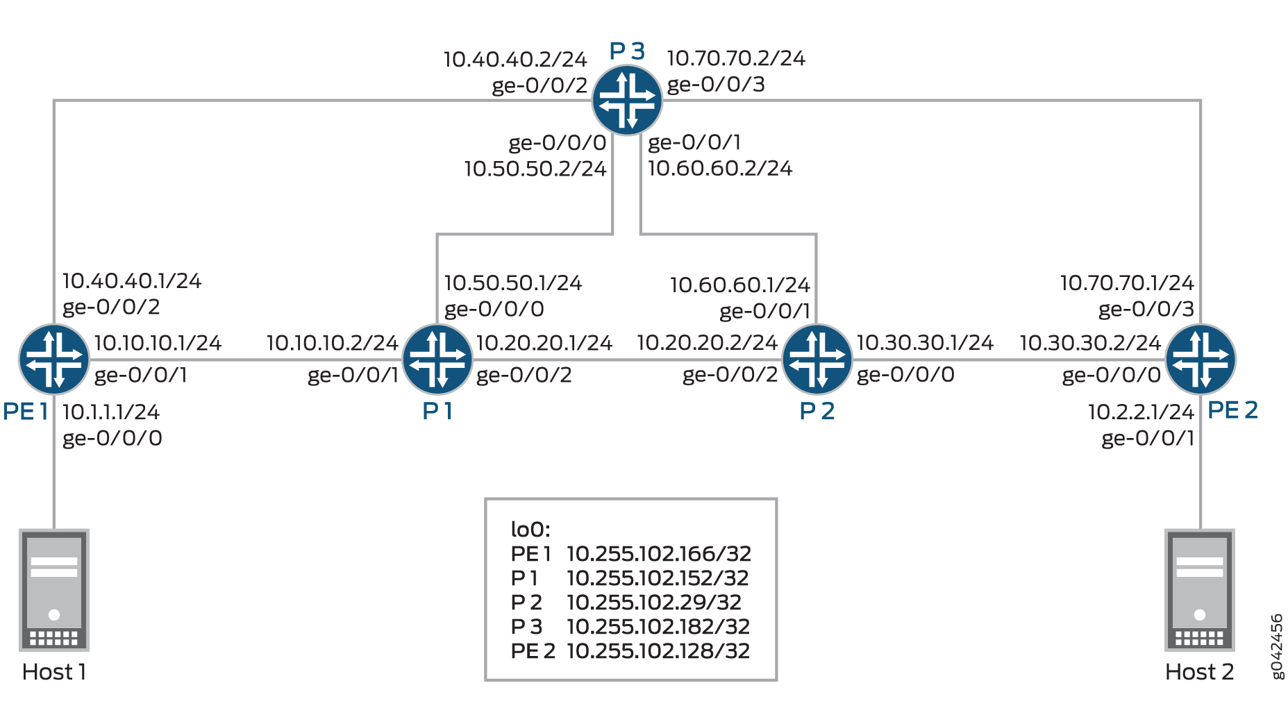
In this example, Routers PE1 and PE2 are the PE routers connected to hosts Host1 and Host2, respectively. The core routers, Routers P1, and P2, and P3 connect to the PE routers.
Configuration
CLI Quick Configuration
To quickly configure this example, copy the following commands, paste them into a
text file, remove any line breaks, change any details necessary to match your
network configuration, copy and paste the commands into the CLI at the
[edit] hierarchy level, and then enter
commit from configuration mode.
PE1
set interfaces ge-0/0/0 unit 0 family inet address 10.1.1.1/24
set interfaces ge-0/0/1 unit 0 family inet address 10.10.10.1/24
set interfaces ge-0/0/1 unit 0 family mpls
set interfaces ge-0/0/2 unit 0 family inet address 10.40.40.1/24
set interfaces ge-0/0/2 unit 0 family mpls
set interfaces lo0 unit 0 family inet address 10.255.102.166/32
set interfaces lo0 unit 0 family mpls
set routing-options router-id 10.255.102.166
set routing-options autonomous-system 65034
set routing-options forwarding-table export pplb
set protocols rsvp preemption aggressive
set protocols rsvp interface all aggregate
set protocols rsvp interface fxp0.0 disable
set protocols rsvp interface ge-0/0/1.0
set protocols rsvp interface ge-0/0/2.0
set protocols mpls statistics file auto-bw
set protocols mpls statistics file size 10m
set protocols mpls statistics interval 10
set protocols mpls statistics auto-bandwidth
set protocols mpls label-switched-path PE1-to-PE2-template1 template
set protocols mpls label-switched-path PE1-to-PE2-template1 optimize-timer 30
set protocols mpls label-switched-path PE1-to-PE2-template1 link-protection
set protocols mpls label-switched-path PE1-to-PE2-template1 adaptive
set protocols mpls label-switched-path PE1-to-PE2-template1 auto-bandwidth adjust-interval 300
set protocols mpls label-switched-path PE1-to-PE2-template1 auto-bandwidth adjust-threshold 5
set protocols mpls label-switched-path PE1-to-PE2-template1 auto-bandwidth minimum-bandwidth 10m
set protocols mpls label-switched-path PE1-to-PE2-template1 auto-bandwidth maximum-bandwidth 10m
set protocols mpls container-label-switched-path PE1-PE2-container-100 label-switched-path-template PE1-to-PE2-template1
set protocols mpls container-label-switched-path PE1-PE2-container-100 to 10.255.102.128
set protocols mpls container-label-switched-path PE1-PE2-container-100 splitting-merging maximum-member-lsps 20
set protocols mpls container-label-switched-path PE1-PE2-container-100 splitting-merging minimum-member-lsps 2
set protocols mpls container-label-switched-path PE1-PE2-container-100 splitting-merging splitting-bandwidth 40m
set protocols mpls container-label-switched-path PE1-PE2-container-100 splitting-merging merging-bandwidth 6m
set protocols mpls container-label-switched-path PE1-PE2-container-100 splitting-merging maximum-signaling-bandwidth 10m
set protocols mpls container-label-switched-path PE1-PE2-container-100 splitting-merging minimum-signaling-bandwidth 10m
set protocols mpls container-label-switched-path PE1-PE2-container-100 splitting-merging normalization normalize-interval 400
set protocols mpls container-label-switched-path PE1-PE2-container-100 splitting-merging normalization failover-normalization
set protocols mpls container-label-switched-path PE1-PE2-container-100 splitting-merging normalization normalization-retry-duration 20
set protocols mpls container-label-switched-path PE1-PE2-container-100 splitting-merging normalization normalization-retry-limits 3
set protocols mpls container-label-switched-path PE1-PE2-container-100 splitting-merging sampling cut-off-threshold 1
set protocols mpls container-label-switched-path PE1-PE2-container-100 splitting-merging sampling use-percentile 90
set protocols mpls interface all
set protocols mpls interface fxp0.0 disable
set protocols bgp group to-PE2 type internal
set protocols bgp group to-PE2 local-address 10.255.102.166
set protocols bgp group to-PE2 family inet-vpn unicast
set protocols bgp group to-PE2 export direct
set protocols bgp group to-PE2 neighbor 10.255.102.128
set protocols ospf traffic-engineering
set protocols ospf area 0.0.0.0 interface all
set protocols ospf area 0.0.0.0 interface fxp0.0 disable
set protocols ospf area 0.0.0.0 interface ge-0/0/2.0 metric 100
set policy-options policy-statement direct term 1 from protocol direct
set policy-options policy-statement direct term 1 then accept
set policy-options policy-statement pplb then load-balance per-packet
set routing-instances vpn1 instance-type vrf
set routing-instances vpn1 interface ge-0/0/0.0
set routing-instances vpn1 route-distinguisher 10.255.102.166:1
set routing-instances vpn1 vrf-target target:1:1
set routing-instances vpn1 vrf-table-label
P1
set interfaces ge-0/0/0 unit 0 family inet address 10.50.50.1/24
set interfaces ge-0/0/0 unit 0 family mpls
set interfaces ge-0/0/1 unit 0 family inet address 10.10.10.2/24
set interfaces ge-0/0/1 unit 0 family mpls
set interfaces ge-0/0/2 unit 0 family inet address 10.20.20.1/24
set interfaces ge-0/0/2 unit 0 family mpls
set interfaces lo0 unit 0 family inet address 10.255.102.152/32
set protocols rsvp interface all aggregate
set protocols rsvp interface fxp0.0 disable
set protocols mpls interface all
set protocols mpls interface fxp0.0 disable
set protocols ospf traffic-engineering
set protocols ospf area 0.0.0.0 interface all
set protocols ospf area 0.0.0.0 interface fxp0.0 disable
set protocols ospf area 0.0.0.0 interface ge-0/0/0.0 metric 100
P2
set interfaces ge-0/0/0 unit 0 family inet address 10.30.30.1/24
set interfaces ge-0/0/0 unit 0 family mpls
set interfaces ge-0/0/1 unit 0 family inet address 10.60.60.1/24
set interfaces ge-0/0/1 unit 0 family mpls
set interfaces ge-0/0/2 unit 0 family inet address 10.20.20.2/24
set interfaces ge-0/0/2 unit 0 family mpls
set interfaces lo0 unit 0 family inet address 10.255.102.29/32
set protocols rsvp interface all aggregate
set protocols rsvp interface fxp0.0 disable
set protocols mpls statistics file auto_bw
set protocols mpls statistics file size 10m
set protocols mpls statistics interval 5
set protocols mpls statistics auto-bandwidth
set protocols mpls icmp-tunneling
set protocols mpls interface all
set protocols mpls interface fxp0.0 disable
set protocols ospf traffic-engineering
set protocols ospf area 0.0.0.0 interface all
set protocols ospf area 0.0.0.0 interface fxp0.0 disable
set protocols ospf area 0.0.0.0 interface ge-0/0/1.0 metric 100
P3
set interfaces ge-0/0/0 unit 0 family inet address 10.50.50.2/24
set interfaces ge-0/0/0 unit 0 family mpls
set interfaces ge-0/0/1 unit 0 family inet address 10.60.60.2/24
set interfaces ge-0/0/1 unit 0 family mpls
set interfaces ge-0/0/2 unit 0 family inet address 10.40.40.2/24
set interfaces ge-0/0/2 unit 0 family mpls
set interfaces ge-0/0/3 unit 0 family inet address 10.70.70.2/24
set interfaces ge-0/0/3 unit 0 family mpls
set interfaces lo0 unit 0 family inet address 10.255.102.182/32
set protocols rsvp interface all aggregate
set protocols rsvp interface fxp0.0 disable
set protocols mpls icmp-tunneling
set protocols mpls interface all
set protocols mpls interface fxp0.0 disable
set protocols ospf traffic-engineering
set protocols ospf area 0.0.0.0 interface all
set protocols ospf area 0.0.0.0 interface fxp0.0 disable
PE2
set interfaces ge-0/0/0 unit 0 family inet address 10.30.30.2/24
set interfaces ge-0/0/0 unit 0 family mpls
set interfaces ge-0/0/1 unit 0 family inet address 10.2.2.1/24
set interfaces ge-0/0/3 unit 0 family inet address 10.70.70.1/24
set interfaces ge-0/0/3 unit 0 family mpls
set interfaces lo0 unit 0 family inet address 10.255.102.128/32
set interfaces lo0 unit 0 family mpls
set routing-options router-id 10.255.102.128
set routing-options autonomous-system 65034
set protocols rsvp interface all aggregate
set protocols rsvp interface fxp0.0 disable
set protocols mpls interface all
set protocols mpls interface fxp0.0 disable
set protocols bgp group to-PE1 type internal
set protocols bgp group to-PE1 local-address 10.255.102.128
set protocols bgp group to-PE1 family inet-vpn unicast
set protocols bgp group to-PE1 neighbor 10.255.102.166
set protocols ospf traffic-engineering
set protocols ospf area 0.0.0.0 interface all
set protocols ospf area 0.0.0.0 interface fxp0.0 disable
set policy-options policy-statement direct from protocol direct
set policy-options policy-statement direct then accept
set routing-instances vpn1 instance-type vrf
set routing-instances vpn1 interface ge-0/0/1.0
set routing-instances vpn1 route-distinguisher 10.255.102.128:1
set routing-instances vpn1 vrf-target target:1:1
set routing-instances vpn1 vrf-table-label
Procedure
Step-by-Step Procedure
The following example requires that you navigate various levels in the configuration hierarchy. For information about navigating the CLI, see Using the CLI Editor in Configuration Mode in the CLI User Guide.
To configure Router PE1:
-
Configure the Router PE1 interfaces.
[edit interfaces]
user@PE1# set ge-0/0/0 unit 0 family inet address 10.1.1.1/24
user@PE1# set ge-0/0/1 unit 0 family inet address 10.10.10.1/24
user@PE1# set ge-0/0/1 unit 0 family mpls
user@PE1# set ge-0/0/2 unit 0 family inet address 10.40.40.1/24
user@PE1# set ge-0/0/2 unit 0 family mpls
user@PE1# set lo0 unit 0 family inet address 10.255.102.166/32
user@PE1# set lo0 unit 0 family mpls
-
Configure the router ID and autonomous system number for Router PE1.
[edit routing-options]
user@PE1# set router-id 10.255.102.166
user@PE1# set autonomous-system 65034
-
Enable the policy to load-balance traffic.
[edit routing-options]
user@PE1# set forwarding-table export pplb
-
Enable RSVP on all Router PE1 interfaces (excluding the management interface).
[edit protocols]
user@PE1# set rsvp preemption aggressive
user@PE1# set rsvp interface all aggregate
user@PE1# set rsvp interface fxp0.0 disable
user@PE1# set rsvp interface ge-0/0/1.0
user@PE1# set rsvp interface ge-0/0/2.0
-
Enable MPLS on all the interfaces of Router PE1 (excluding the management interface).
[edit protocols]
user@PE1# set mpls interface all
user@PE1# set mpls interface fxp0.0 disable
-
Configure the MPLS statistics parameters.
[edit protocols]
user@PE1# set mpls statistics file auto-bw
user@PE1# set mpls statistics file size 10m
user@PE1# set mpls statistics interval 10
user@PE1# set mpls statistics auto-bandwidth
-
Configure the label-switched path (LSP) template parameters.
[edit protocols]
user@PE1# set mpls label-switched-path PE1-to-PE2-template1 template
user@PE1# set mpls label-switched-path PE1-to-PE2-template1 optimize-timer 30
user@PE1# set mpls label-switched-path PE1-to-PE2-template1 link-protection
user@PE1# set mpls label-switched-path PE1-to-PE2-template1 adaptive
user@PE1# set mpls label-switched-path PE1-to-PE2-template1 auto-bandwidth adjust-interval 300
user@PE1# set mpls label-switched-path PE1-to-PE2-template1 auto-bandwidth adjust-threshold 5
user@PE1# set mpls label-switched-path PE1-to-PE2-template1 auto-bandwidth minimum-bandwidth 10m
user@PE1# set mpls label-switched-path PE1-to-PE2-template1 auto-bandwidth maximum-bandwidth 10m
-
Configure a container LSP between Router PE1 and Router PE2, and assign the PE1-to-PE2-template1 LSP template.
[edit protocols]
user@PE1# set mpls container-label-switched-path PE1-PE2-container-100 to 10.255.102.128
user@PE1# set mpls container-label-switched-path PE1-PE2-container-100 label-switched-path-template PE1-to-PE2-template1
-
Configure the container LSP parameters.
[edit protocols]
user@PE1# set mpls container-label-switched-path PE1-PE2-container-100 splitting-merging maximum-member-lsps 20
user@PE1# set mpls container-label-switched-path PE1-PE2-container-100 splitting-merging minimum-member-lsps 2
user@PE1# set mpls container-label-switched-path PE1-PE2-container-100 splitting-merging splitting-bandwidth 40m
user@PE1# set mpls container-label-switched-path PE1-PE2-container-100 splitting-merging merging-bandwidth 6m
user@PE1# set mpls container-label-switched-path PE1-PE2-container-100 splitting-merging maximum-signaling-bandwidth 10m
user@PE1# set mpls container-label-switched-path PE1-PE2-container-100 splitting-merging minimum-signaling-bandwidth 10m
user@PE1# set mpls container-label-switched-path PE1-PE2-container-100 splitting-merging normalization normalize-interval 400
user@PE1# set mpls container-label-switched-path PE1-PE2-container-100 splitting-merging normalization failover-normalization
user@PE1# set mpls container-label-switched-path PE1-PE2-container-100 splitting-merging normalization normalization-retry-duration 20
user@PE1# set mpls container-label-switched-path PE1-PE2-container-100 splitting-merging normalization normalization-retry-limits 3
user@PE1# set mpls container-label-switched-path PE1-PE2-container-100 splitting-merging sampling cut-off-threshold 1
user@PE1# set mpls container-label-switched-path PE1-PE2-container-100 splitting-merging sampling use-percentile 90
-
Configure the BGP group, and assign the local and neighbor IP addresses.
[edit protocols]
user@PE1# set bgp group to-PE2 type internal
user@PE1# set bgp group to-PE2 local-address 10.255.102.166
user@PE1# set bgp group to-PE2 neighbor 10.255.102.128
user@PE1# set bgp group to-PE2 family inet-vpn unicast
user@PE1# set bgp group to-PE2 export direct
-
Enable OSPF on all the interfaces of Router PE1 (excluding the management interface) along with traffic engineering capabilities.
[edit protocols]
user@PE1# set ospf traffic-engineering
user@PE1# set ospf area 0.0.0.0 interface all
user@PE1# set ospf area 0.0.0.0 interface fxp0.0 disable
user@PE1# set ospf area 0.0.0.0 interface ge-0/0/2.0 metric 100
-
Configure the policy statement to load-balance traffic.
[edit policy-options]
user@PE1# set policy-statement direct term 1 from protocol direct
user@PE1# set policy-statement direct term 1 then accept
user@PE1# set policy-statement pplb then load-balance per-packet
-
Configure a routing instance on Router PE1, and assign the routing instance interface.
[edit routing-instances]
user@PE1# set vpn1 instance-type vrf
user@PE1# set vpn1 interface ge-0/0/0.0
-
Configure the route distinguisher, vrf target, and vrf-table label values for the VRF routing instance.
[edit routing-instances]
user@PE1# set vpn1 route-distinguisher 10.255.102.166:1
user@PE1# set vpn1 vrf-target target:1:1
user@PE1# set vpn1 vrf-table-label
Results
From configuration mode, confirm your configuration by entering the
show interfaces, show routing-options,
show protocols, show policy-options,
and show routing-options commands. If the output does not
display the intended configuration, repeat the instructions in this example
to correct the configuration.
user@PE1# show interfaces
ge-0/0/0 {
    unit 0 {
        family inet {
            address 10.1.1.1/24;
        }
    }
}
ge-0/0/1 {
    unit 0 {
        family inet {
            address 10.10.10.1/24;
        }
        family mpls;
    }
}
ge-0/0/2 {
    unit 0 {
        family inet {
            address 10.40.40.1/24;
        }
        family mpls;
    }
}
lo0 {
    unit 0 {
        family inet {
            address 10.255.102.166/32;
        }
        family mpls;
    }
}
user@PE1# show routing-options
router-id 10.255.102.166;
autonomous-system 65034;
forwarding-table {
    export pplb;
}
user@PE1# show protocols
rsvp {
    preemption aggressive;
    interface all {
        aggregate;
    }
    interface fxp0.0 {
        disable;
    }
    interface ge-0/0/1.0;
    interface ge-0/0/2.0;
}
mpls {
    statistics {
        file auto-bw size 10m;
        interval 10;
        auto-bandwidth;
    }
    label-switched-path PE1-to-PE2-template1 {
        template;
        optimize-timer 30;
        link-protection;
        adaptive;
        auto-bandwidth {
            adjust-interval 300;
            adjust-threshold 5;
            minimum-bandwidth 10m;
            maximum-bandwidth 10m;
        }
    }
    container-label-switched-path PE1-PE2-container-100 {
        label-switched-path-template {
            PE1-to-PE2-template1;
        }
        to 10.255.102.128;
        splitting-merging {
            maximum-member-lsps 20;
            minimum-member-lsps 2;
            splitting-bandwidth 40m;
            merging-bandwidth 6m;
            maximum-signaling-bandwidth 10m;
            minimum-signaling-bandwidth 10m;
            normalization {
                normalize-interval 400;
                failover-normalization;
                normalization-retry-duration 20;
                normalization-retry-limits 3;
            }
            sampling {
                cut-off-threshold 1;
                use-percentile 90;
            }
        }
    }
    interface all;
    interface fxp0.0 {
        disable;
    }
}
bgp {
    group to-PE2 {
        type internal;
        local-address 10.255.102.166;
        family inet-vpn {
            unicast;
        }
        export direct;
        neighbor 10.255.102.128;
    }
}
ospf {
    traffic-engineering;
    area 0.0.0.0 {
        interface all;
        interface fxp0.0 {
            disable;
        }
        interface ge-0/0/2.0 {
            metric 100;
        }
    }
}
user@PE1# show policy-options
policy-statement direct {
    term 1 {
        from protocol direct;
        then accept;
    }
}
policy-statement pplb {
    then load-balance {
        per-packet;
    }
}
user@PE1# show routing-instances
vpn1 {
    instance-type vrf;
    interface ge-0/0/0.0;
    route-distinguisher 10.255.102.166:1;
    vrf-target target:1:1;
    vrf-table-label;
}
Verification
Confirm that the configuration is working properly.
- Verifying the Container LSP Status Without Bandwidth
- Verifying the Container LSP Status with Increased Bandwidth (Before Normalization)
- Verifying the Container LSP Status with Increased Bandwidth (After Normalization)
- Verifying the Container LSP Splitting Process
- Verifying the Container LSP Statistics
- Verifying the Container LSP Status with Decreased Bandwidth (Before Normalization)
- Verifying the Container LSP Status with Decreased Bandwidth (After Normalization)
- Verifying the Container LSP Merging Process
- Verifying Failover Normalization
- Verifying Incremental Normalization
Verifying the Container LSP Status Without Bandwidth
Purpose
Verify the status of the container LSP.
Action
From operational mode, run the show mpls container-lsp extensive command.
user@PE1> show mpls container-lsp extensive
Ingress LSP: 1 sessions
Container LSP name: PE1-PE2-container-100, State: Up, Member count: 2
 Normalization
  Min LSPs: 2, Max LSPs: 20
  Aggregate bandwidth: 20Mbps, Sampled Aggregate bandwidth: 0bps
  NormalizeTimer: 400 secs, NormalizeThreshold: 10%
  Max Signaling BW: 10Mbps, Min Signaling BW: 10Mbps, Splitting BW: 40Mbps, Merging BW: 6Mbps
  Mode: incremental-normalization, failover-normalization
  Sampling: Outlier cut-off 1, Percentile 90 of Aggregate
  Normalization in 143 second(s)
   36 Jun  5 04:12:17.497 Clear history and statistics: on container (PE1-PE2-container-100)
   35 Jun  5 04:12:17.497 Avoid normalization: not needed with bandwidth 0 bps
   34 Jun  5 04:05:37.484 Clear history and statistics: on container (PE1-PE2-container-100)
   33 Jun  5 04:05:37.484 Avoid normalization: not needed with bandwidth 0 bps
   32 Jun  5 03:58:57.470 Clear history and statistics: on container (PE1-PE2-container-100)
   31 Jun  5 03:58:57.470 Avoid normalization: not needed with bandwidth 0 bps
   30 Jun  5 03:52:17.455 Clear history and statistics: on container (PE1-PE2-container-100)
   29 Jun  5 03:52:17.455 Avoid normalization: not needed with bandwidth 0 bps
   28 Jun  5 03:45:37.440 Clear history and statistics: on container (PE1-PE2-container-100)
   27 Jun  5 03:45:37.440 Avoid normalization: not needed with bandwidth 0 bps
   26 Jun  5 03:38:59.013 Normalization complete: container (PE1-PE2-container-100) with 2 members
   25 Jun  5 03:38:57.423 Delete member LSPs: PE1-PE2-container-100-3 through PE1-PE2-container-100-7
   24 Jun  5 03:38:57.423 Normalize: container (PE1-PE2-container-100) create 2 LSPs, min bw 10000000bps, member count 7
   23 Jun  5 03:38:57.423 Normalize: normalization with aggregate bandwidth 0 bps
   22 Jun  5 03:32:19.019 Normalization complete: container (PE1-PE2-container-100) with 7 members
   21 Jun  5 03:32:17.404 Clear history and statistics: on container (PE1-PE2-container-100)
   20 Jun  5 03:32:17.403 Normalize: container (PE1-PE2-container-100) into 7 members - each with bandwidth 10000000 bps
   19 Jun  5 03:32:17.403 Normalize: normalization with aggregate bandwidth 62914560 bps
   18 Jun  5 03:32:17.403 Normalize: normalizaton with 62914560 bps
   17 Jun  5 03:32:09.219 Normalization complete: container (PE1-PE2-container-100) with 7 members
   16 Jun  5 03:32:07.600 Clear history and statistics: on container (PE1-PE2-container-100)
   15 Jun  5 03:32:07.600 Normalize: container (PE1-PE2-container-100) into 7 members - each with bandwidth 10000000 bps
   14 Jun  5 03:32:07.599 Normalize: normalization with aggregate bandwidth 62914560 bps
   13 Jun  5 03:32:07.599 Normalize: normalizaton with 62914560 bps
   12 Jun  5 03:26:57.295 Clear history and statistics: on container (PE1-PE2-container-100)
   11 Jun  5 03:26:57.295 Avoid normalization: not needed with bandwidth 0 bps
   10 Jun  5 03:20:18.297 Normalization complete: container (PE1-PE2-container-100) with 2 members
    9 Jun  5 03:20:17.281 Normalize: container (PE1-PE2-container-100) create 2 LSPs, min bw 10000000bps, member count 0
    8 Jun  5 03:20:17.281 Normalize: normalization with aggregate bandwidth 0 bps
    7 Jun  5 03:17:43.218 Clear history and statistics: on container (PE1-PE2-container-100)
    6 Jun  5 03:17:43.218 Avoid normalization: not needed with bandwidth 0 bps
    5 Jun  5 03:17:43.212 Normalize: container (PE1-PE2-container-100) received PathErr on member PE1-PE2-container-100-2
    4 Jun  5 03:17:43.212 Normalize: container (PE1-PE2-container-100) received PathErr on member PE1-PE2-container-100-1
    3 Jun  5 03:12:47.323 Normalization complete: container (PE1-PE2-container-100) with 2 members
    2 Jun  5 03:12:16.555 Normalize: container (PE1-PE2-container-100) create 2 LSPs, min bw 10000000bps, member count 0
    1 Jun  5 03:12:16.555 Normalize: normalization with aggregate bandwidth 0 bps

10.255.102.128
  From: 10.255.102.166, State: Up, ActiveRoute: 0, LSPname: PE1-PE2-container-100-1
  ActivePath:  (primary)
  LSPtype: Dynamic Configured, Penultimate hop popping
  LoadBalance: Random
  Autobandwidth
  MinBW: 10Mbps, MaxBW: 10Mbps
  AdjustTimer: 300 secs
  Max AvgBW util: 0bps, Bandwidth Adjustment in 12 second(s).
  Overflow limit: 0, Overflow sample count: 0
  Underflow limit: 0, Underflow sample count: 0, Underflow Max AvgBW: 0bps
  Encoding type: Packet, Switching type: Packet, GPID: IPv4
 *Primary                    State: Up
    Priorities: 7 0
    Bandwidth: 10Mbps
    SmartOptimizeTimer: 180
    Computed ERO (S [L] denotes strict [loose] hops): (CSPF metric: 3)
 10.10.10.2 S 10.20.20.2 S 10.30.30.2 S
    Received RRO (ProtectionFlag 1=Available 2=InUse 4=B/W 8=Node 10=SoftPreempt 20=Node-ID):
          10.10.10.2 10.20.20.2 10.30.30.2
   17 Jun  5 03:38:59.013 Make-before-break: Switched to new instance
   16 Jun  5 03:38:58.003 Record Route:  10.10.10.2 10.20.20.2 3=10.30.30.2
   15 Jun  5 03:38:58.003 Up
   14 Jun  5 03:38:57.423 Originate make-before-break call
   13 Jun  5 03:38:57.423 CSPF: computation result accepted  10.10.10.2 10.20.20.2 10.30.30.2
   12 Jun  5 03:33:30.400 CSPF: computation result ignored, new path no benefit
   11 Jun  5 03:32:17.403 Pending old path instance deletion
   10 Jun  5 03:32:09.218 Make-before-break: Switched to new instance
    9 Jun  5 03:32:08.202 Record Route:  10.10.10.2 10.20.20.2 10.30.30.2
    8 Jun  5 03:32:08.202 Up
    7 Jun  5 03:32:07.603 Originate make-before-break call
    6 Jun  5 03:32:07.603 CSPF: computation result accepted  10.10.10.2 10.20.20.2 10.30.30.2
    5 Jun  5 03:20:18.278 Selected as active path
    4 Jun  5 03:20:18.277 Record Route:  10.10.10.2 10.20.20.2 10.30.30.2
    3 Jun  5 03:20:18.277 Up
    2 Jun  5 03:20:17.281 Originate Call
    1 Jun  5 03:20:17.281 CSPF: computation result accepted  10.10.10.2 10.20.20.2 10.30.30.2
  Created: Thu Jun  5 03:20:16 2014

10.255.102.128
  From: 10.255.102.166, State: Up, ActiveRoute: 0, LSPname: PE1-PE2-container-100-2
  ActivePath:  (primary)
  LSPtype: Dynamic Configured, Penultimate hop popping
  LoadBalance: Random
  Autobandwidth
  MinBW: 10Mbps, MaxBW: 10Mbps
  AdjustTimer: 300 secs
  Max AvgBW util: 0bps, Bandwidth Adjustment in 76 second(s).
  Overflow limit: 0, Overflow sample count: 0
  Underflow limit: 0, Underflow sample count: 0, Underflow Max AvgBW: 0bps
  Encoding type: Packet, Switching type: Packet, GPID: IPv4
 *Primary                    State: Up
    Priorities: 7 0
    Bandwidth: 10Mbps
    SmartOptimizeTimer: 180
    Computed ERO (S [L] denotes strict [loose] hops): (CSPF metric: 3)
 10.10.10.2 S 10.20.20.2 S 10.30.30.2 S
    Received RRO (ProtectionFlag 1=Available 2=InUse 4=B/W 8=Node 10=SoftPreempt 20=Node-ID):
          10.10.10.2 10.20.20.2 10.30.30.2
   17 Jun  5 03:38:59.013 Make-before-break: Switched to new instance
   16 Jun  5 03:38:58.002 Record Route:  10.10.10.2 10.20.20.2 10.30.30.2
   15 Jun  5 03:38:58.002 Up
   14 Jun  5 03:38:57.423 Originate make-before-break call
   13 Jun  5 03:38:57.423 CSPF: computation result accepted  10.10.10.2 10.20.20.2 10.30.30.2
   12 Jun  5 03:33:26.189 CSPF: computation result ignored, new path no benefit
   11 Jun  5 03:32:17.403 Pending old path instance deletion
   10 Jun  5 03:32:09.219 Make-before-break: Switched to new instance
    9 Jun  5 03:32:08.204 Record Route:  10.10.10.2 10.20.20.2 10.30.30.2
    8 Jun  5 03:32:08.204 Up
    7 Jun  5 03:32:07.603 Originate make-before-break call
    6 Jun  5 03:32:07.603 CSPF: computation result accepted  10.10.10.2 10.20.20.2 10.30.30.2
    5 Jun  5 03:20:18.297 Selected as active path
    4 Jun  5 03:20:18.295 Record Route:  10.10.10.2 10.20.20.2 10.30.30.2
    3 Jun  5 03:20:18.295 Up
    2 Jun  5 03:20:17.281 Originate Call
    1 Jun  5 03:20:17.281 CSPF: computation result accepted  10.10.10.2 10.20.20.2 10.30.30.2
  Created: Thu Jun  5 03:20:16 2014
Total 2 displayed, Up 2, Down 0

Egress LSP: 0 sessions
Total 0 displayed, Up 0, Down 0

Transit LSP: 0 sessions
Total 0 displayed, Up 0, Down 0
Meaning
The container LSP is established between Routers PE1 and PE2.
Verifying the Container LSP Status with Increased Bandwidth (Before Normalization)
Purpose
Verify the status of the container LSP with increased bandwidth before normalization happens.
Action
From operational mode, run the show mpls container-lsp extensive command.
user@PE1> show mpls container-lsp extensive
Ingress LSP: 1 sessions
Container LSP name: PE1-PE2-container-100, State: Up, Member count: 2
 Normalization
  Min LSPs: 2, Max LSPs: 20
  Aggregate bandwidth: 20Mbps, Sampled Aggregate bandwidth: 42.6984Mbps
  NormalizeTimer: 400 secs, NormalizeThreshold: 10%
  Max Signaling BW: 10Mbps, Min Signaling BW: 10Mbps, Splitting BW: 40Mbps, Merging BW: 6Mbps
  Mode: incremental-normalization, failover-normalization
  Sampling: Outlier cut-off 1, Percentile 90 of Aggregate
  Normalization in 321 second(s)
    3 Jun  5 21:22:34.731 Normalization complete: container (PE1-PE2-container-100) with 2 members
    2 Jun  5 21:22:15.503 Normalize: container (PE1-PE2-container-100) create 2 LSPs, min bw 10000000bps, member count 0
    1 Jun  5 21:22:15.503 Normalize: normalization with aggregate bandwidth 0 bps

10.255.102.128
  From: 10.255.102.166, State: Up, ActiveRoute: 0, LSPname: PE1-PE2-container-100-1
  ActivePath:  (primary)
  Link protection desired
  LSPtype: Dynamic Configured, Penultimate hop popping
  LoadBalance: Random
  Autobandwidth
  MinBW: 10Mbps, MaxBW: 10Mbps
  AdjustTimer: 300 secs AdjustThreshold: 5%
  Max AvgBW util: 23.9893Mbps, Bandwidth Adjustment in 221 second(s).
  Overflow limit: 0, Overflow sample count: 6
  Underflow limit: 0, Underflow sample count: 0, Underflow Max AvgBW: 0bps
  Encoding type: Packet, Switching type: Packet, GPID: IPv4
 *Primary                    State: Up
    Priorities: 7 0
    Bandwidth: 10Mbps
    OptimizeTimer: 30
    SmartOptimizeTimer: 180
    Reoptimization in 9 second(s).
    Computed ERO (S [L] denotes strict [loose] hops): (CSPF metric: 3)
 10.10.10.2 S 10.20.20.2 S 10.30.30.2 S
    Received RRO (ProtectionFlag 1=Available 2=InUse 4=B/W 8=Node 10=SoftPreempt 20=Node-ID):
          10.255.102.166(flag=0x20) 10.10.10.2(Label=303440) 10.255.102.29(flag=0x20) 10.20.20.2(Label=302144) 10.255.102.128(flag=0x20) 10.30.30.2(Label=3)

10.255.102.128
  From: 10.255.102.166, State: Up, ActiveRoute: 0, LSPname: PE1-PE2-container-100-2
  ActivePath:  (primary)
  Link protection desired
  LSPtype: Dynamic Configured, Penultimate hop popping
  LoadBalance: Random
  Autobandwidth
  MinBW: 10Mbps, MaxBW: 10Mbps
  AdjustTimer: 300 secs AdjustThreshold: 5%
  Max AvgBW util: 22.1438Mbps, Bandwidth Adjustment in 221 second(s).
  Overflow limit: 0, Overflow sample count: 6
  Underflow limit: 0, Underflow sample count: 0, Underflow Max AvgBW: 0bps
  Encoding type: Packet, Switching type: Packet, GPID: IPv4
 *Primary                    State: Up
    Priorities: 7 0
    Bandwidth: 10Mbps
    OptimizeTimer: 30
    SmartOptimizeTimer: 180
    Reoptimization in 9 second(s).
    Computed ERO (S [L] denotes strict [loose] hops): (CSPF metric: 3)
 10.10.10.2 S 10.20.20.2 S 10.30.30.2 S
    Received RRO (ProtectionFlag 1=Available 2=InUse 4=B/W 8=Node 10=SoftPreempt 20=Node-ID):
          10.255.102.166(flag=0x20) 10.10.10.2(Label=303456) 10.255.102.29(flag=0x20) 10.20.20.2(Label=302160) 10.255.102.128(flag=0x20) 10.30.30.2(Label=3)

Total 2 displayed, Up 2, Down 0
Meaning
Because normalization has not happened, the member LSP count remains at 2.
Verifying the Container LSP Status with Increased Bandwidth (After Normalization)
Purpose
Verify the status of the container LSP with increased bandwidth after normalization happens.
Action
From operational mode, run the show mpls container-lsp extensive command.
user@PE1> show mpls container-lsp extensive
Ingress LSP: 1 sessions
Container LSP name: PE1-PE2-container-100, State: Up, Member count: 5
 Normalization
  Min LSPs: 2, Max LSPs: 20
  Aggregate bandwidth: 50Mbps, Sampled Aggregate bandwidth: 45.8873Mbps
  NormalizeTimer: 400 secs, NormalizeThreshold: 10%
  Max Signaling BW: 10Mbps, Min Signaling BW: 10Mbps, Splitting BW: 40Mbps, Merging BW: 6Mbps
  Mode: incremental-normalization, failover-normalization
  Sampling: Outlier cut-off 1, Percentile 90 of Aggregate
  Normalization in 169 second(s)
    7 Jun  5 21:29:02.921 Normalization complete: container (PE1-PE2-container-100) with 5 members
    6 Jun  5 21:28:55.505 Clear history and statistics: on container (PE1-PE2-container-100)
    5 Jun  5 21:28:55.505 Normalize: container (PE1-PE2-container-100) into 5 members - each with bandwidth 10000000 bps
    4 Jun  5 21:28:55.504 Normalize: normalization with aggregate bandwidth 45281580 bps
    3 Jun  5 21:22:34.731 Normalization complete: container (PE1-PE2-container-100) with 2 members
    2 Jun  5 21:22:15.503 Normalize: container (PE1-PE2-container-100) create 2 LSPs, min bw 10000000bps, member count 0
    1 Jun  5 21:22:15.503 Normalize: normalization with aggregate bandwidth 0 bps

10.255.102.128
  From: 10.255.102.166, State: Up, ActiveRoute: 0, LSPname: PE1-PE2-container-100-1
  ActivePath:  (primary)
  Link protection desired
  LSPtype: Dynamic Configured, Penultimate hop popping
  LoadBalance: Random
  Autobandwidth
  MinBW: 10Mbps, MaxBW: 10Mbps
  AdjustTimer: 300 secs AdjustThreshold: 5%
  Max AvgBW util: 11.0724Mbps, Bandwidth Adjustment in 129 second(s).
  Overflow limit: 0, Overflow sample count: 1
  Underflow limit: 0, Underflow sample count: 0, Underflow Max AvgBW: 0bps
  Encoding type: Packet, Switching type: Packet, GPID: IPv4
 *Primary                    State: Up
    Priorities: 7 0
    Bandwidth: 10Mbps
    OptimizeTimer: 30
    SmartOptimizeTimer: 180
    Reoptimization in 12 second(s).
    Computed ERO (S [L] denotes strict [loose] hops): (CSPF metric: 3)
 10.10.10.2 S 10.20.20.2 S 10.30.30.2 S
    Received RRO (ProtectionFlag 1=Available 2=InUse 4=B/W 8=Node 10=SoftPreempt 20=Node-ID):
          10.255.102.166(flag=0x20) 10.10.10.2(Label=303488) 10.255.102.29(flag=0x20) 10.20.20.2(Label=302224) 10.255.102.128(flag=0x20) 10.30.30.2(Label=3)

10.255.102.128
  From: 10.255.102.166, State: Up, ActiveRoute: 0, LSPname: PE1-PE2-container-100-2
  ActivePath:  (primary)
  Link protection desired
  LSPtype: Dynamic Configured, Penultimate hop popping
  LoadBalance: Random
  Autobandwidth
  MinBW: 10Mbps, MaxBW: 10Mbps
  AdjustTimer: 300 secs AdjustThreshold: 5%
  Max AvgBW util: 8.50751Mbps, Bandwidth Adjustment in 189 second(s).
  Overflow limit: 0, Overflow sample count: 0
  Underflow limit: 0, Underflow sample count: 11, Underflow Max AvgBW: 8.50751Mbps
  Encoding type: Packet, Switching type: Packet, GPID: IPv4
 *Primary                    State: Up
    Priorities: 7 0
    Bandwidth: 10Mbps
    OptimizeTimer: 30
    SmartOptimizeTimer: 180
    Reoptimization in 6 second(s).
    Computed ERO (S [L] denotes strict [loose] hops): (CSPF metric: 3)
 10.10.10.2 S 10.20.20.2 S 10.30.30.2 S
    Received RRO (ProtectionFlag 1=Available 2=InUse 4=B/W 8=Node 10=SoftPreempt 20=Node-ID):
          10.255.102.166(flag=0x20) 10.10.10.2(Label=303504) 10.255.102.29(flag=0x20) 10.20.20.2(Label=302240) 10.255.102.128(flag=0x20) 10.30.30.2(Label=3)

10.255.102.128
  From: 10.255.102.166, State: Up, ActiveRoute: 0, LSPname: PE1-PE2-container-100-3
  ActivePath:  (primary)
  Link protection desired
  LSPtype: Dynamic Configured, Penultimate hop popping
  LoadBalance: Random
  Autobandwidth
  MinBW: 10Mbps, MaxBW: 10Mbps
  AdjustTimer: 300 secs AdjustThreshold: 5%
  Max AvgBW util: 9.59422Mbps, Bandwidth Adjustment in 249 second(s).
  Overflow limit: 0, Overflow sample count: 0
  Underflow limit: 0, Underflow sample count: 5, Underflow Max AvgBW: 9.59422Mbps
  Encoding type: Packet, Switching type: Packet, GPID: IPv4
 *Primary                    State: Up
    Priorities: 7 0
    Bandwidth: 10Mbps
    OptimizeTimer: 30
    SmartOptimizeTimer: 180
    Reoptimization in 25 second(s).
    Computed ERO (S [L] denotes strict [loose] hops): (CSPF metric: 3)
 10.10.10.2 S 10.20.20.2 S 10.30.30.2 S
    Received RRO (ProtectionFlag 1=Available 2=InUse 4=B/W 8=Node 10=SoftPreempt 20=Node-ID):
          10.255.102.166(flag=0x20) 10.10.10.2(Label=303472) 10.255.102.29(flag=0x20) 10.20.20.2(Label=302176) 10.255.102.128(flag=0x20) 10.30.30.2(Label=3)

10.255.102.128
  From: 10.255.102.166, State: Up, ActiveRoute: 0, LSPname: PE1-PE2-container-100-4
  ActivePath:  (primary)
  Link protection desired
  LSPtype: Dynamic Configured, Penultimate hop popping
  LoadBalance: Random
  Autobandwidth
  MinBW: 10Mbps, MaxBW: 10Mbps
  AdjustTimer: 300 secs AdjustThreshold: 5%
  Max AvgBW util: 9.16169Mbps, Bandwidth Adjustment in 9 second(s).
  Overflow limit: 0, Overflow sample count: 0
  Underflow limit: 0, Underflow sample count: 29, Underflow Max AvgBW: 9.16169Mbps
  Encoding type: Packet, Switching type: Packet, GPID: IPv4
 *Primary                    State: Up
    Priorities: 7 0
    Bandwidth: 10Mbps
    OptimizeTimer: 30
    SmartOptimizeTimer: 180
    Reoptimization in 1 second(s).
    Computed ERO (S [L] denotes strict [loose] hops): (CSPF metric: 3)
 10.10.10.2 S 10.20.20.2 S 10.30.30.2 S
    Received RRO (ProtectionFlag 1=Available 2=InUse 4=B/W 8=Node 10=SoftPreempt 20=Node-ID):
          10.255.102.166(flag=0x20) 10.10.10.2(Label=303520) 10.255.102.29(flag=0x20) 10.20.20.2(Label=302192) 10.255.102.128(flag=0x20) 10.30.30.2(Label=3)

10.255.102.128
  From: 10.255.102.166, State: Up, ActiveRoute: 0, LSPname: PE1-PE2-container-100-5
  ActivePath:  (primary)
  Link protection desired
  LSPtype: Dynamic Configured, Penultimate hop popping
  LoadBalance: Random
  Autobandwidth
  MinBW: 10Mbps, MaxBW: 10Mbps
  AdjustTimer: 300 secs AdjustThreshold: 5%
  Max AvgBW util: 8.39908Mbps, Bandwidth Adjustment in 69 second(s).
  Overflow limit: 0, Overflow sample count: 0
  Underflow limit: 0, Underflow sample count: 23, Underflow Max AvgBW: 8.39908Mbps
  Encoding type: Packet, Switching type: Packet, GPID: IPv4
 *Primary                    State: Up
    Priorities: 7 0
    Bandwidth: 10Mbps
    OptimizeTimer: 30
    SmartOptimizeTimer: 180
    Reoptimization in 17 second(s).
    Computed ERO (S [L] denotes strict [loose] hops): (CSPF metric: 3)
 10.10.10.2 S 20.20.20.2 S 30.30.30.2 S
    Received RRO (ProtectionFlag 1=Available 2=InUse 4=B/W 8=Node 10=SoftPreempt 20=Node-ID):
          10.255.102.166(flag=0x20) 10.10.10.2(Label=303536) 10.255.102.29(flag=0x20) 10.20.20.2(Label=302208) 10.255.102.128(flag=0x20) 10.30.30.2(Label=3)
Total 5 displayed, Up 5, Down 0

Egress LSP: 0 sessions
Total 0 displayed, Up 0, Down 0

Transit LSP: 0 sessions
Total 0 displayed, Up 0, Down 0
Meaning
At the expiry of the normalization timer, the container LSP is split into five member LSPs, each with 10 Mbps (minimum and maximum signaling bandwidth). As a result, the aggregate bandwidth is 50 Mbps.
Verifying the Container LSP Splitting Process
Purpose
Verify the container LSP splitting process after normalization happens.
Action
From operational mode, run the show route 10.2.2.0 command.
user@PE1> show route 10.2.2.0
vpn1.inet.0: 3 destinations, 3 routes (3 active, 0 holddown, 0 hidden)
+ = Active Route, - = Last Active, * = Both

10.2.2.0/24         *[BGP/170] 00:12:14, localpref 100, from 10.255.102.128
                      AS path: I, validation-state: unverified
>to 10.10.10.2 via ge-0/0/1.0,label-switched-path PE1-PE2-container100-1
to 10.10.10.2 via ge-0/0/1.0, label-switched-path PE1-PE2-container100-2
to 10.10.10.2 via ge-0/0/1.0, label-switched-path PE1-PE2-container100-3
to 10.10.10.2 via ge-0/0/1.0, label-switched-path PE1-PE2-container100-4
to 10.10.10.2 via ge-0/0/1.0, label-switched-path PE1-PE2-container100-5
Meaning
After LSP splitting, Router PE1 has injected the forwarding adjacency.
Verifying the Container LSP Statistics
Purpose
Verify the container LSP statistics after normalization happens.
Action
From operational mode, run the show mpls container-lsp statistics command.
user@PE1> show mpls container-lsp statistics
Ingress LSP: 1 sessions
Container LSP name                              State     Member LSP count
PE1-PE2-container-100                           Up                5
To              From             State     Packets            Bytes LSPname
10.255.102.128   10.255.102.166  Up   15166271       2062612856 PE1-PE2-container-100-1
10.255.102.128   10.255.102.166  Up   12289912       1671428032 PE1-PE2-container-100-2
10.255.102.128   10.255.102.166  Up   13866911       1885899896 PE1-PE2-container-100-3
10.255.102.128   10.255.102.166  Up   12558707       1707984152 PE1-PE2-container-100-4
10.255.102.128   10.255.102.166  Up   11512151       1565652536 PE1-PE2-container-100-5
Meaning
Traffic is load-balanced across the newly created member LSPs.
Verifying the Container LSP Status with Decreased Bandwidth (Before Normalization)
Purpose
Verify the status of the container LSP with decreased bandwidth before normalization happens.
Action
From operational mode, run the show mpls container-lsp detail command.
user@PE1> show mpls container-lsp detail
Ingress LSP: 1 sessions
Container LSP name: PE1-PE2-container-100, State: Up, Member count: 5
 Normalization
  Min LSPs: 2, Max LSPs: 20
  Aggregate bandwidth: 50Mbps, Sampled Aggregate bandwidth: 2.0215Mbps
  NormalizeTimer: 400 secs, NormalizeThreshold: 10%
  Max Signaling BW: 10Mbps, Min Signaling BW: 10Mbps, Splitting BW: 40Mbps, Merging BW: 6Mbps
  Mode: incremental-normalization, failover-normalization
  Sampling: Outlier cut-off 1, Percentile 90 of Aggregate
  Normalization in 384 second(s)
---Output truncated---
Meaning
Because normalization has not happened, the member LSP count remains at 5.
Verifying the Container LSP Status with Decreased Bandwidth (After Normalization)
Purpose
Verify the status of the container LSP with decreased bandwidth after normalization happens.
Action
From operational mode, run the show mpls container-lsp detail command.
user@PE1> show mpls container-lsp detail
Ingress LSP: 1 sessions
Container LSP name: PE1-PE2-container-100, State: Up, Member count: 2
 Normalization
  Min LSPs: 2, Max LSPs: 20
  Aggregate bandwidth: 20Mbps, Sampled Aggregate bandwidth: 0bps
  NormalizeTimer: 400 secs, NormalizeThreshold: 10%
  Max Signaling BW: 10Mbps, Min Signaling BW: 10Mbps, Splitting BW: 40Mbps, Merging BW: 6Mbps
  Mode: incremental-normalization, failover-normalization
  Sampling: Outlier cut-off 1, Percentile 90 of Aggregate
  Normalization in 397 second(s)
   22 Jun  5 22:30:37.094 Clear history and statistics: on container (PE1-PE2-container-100)
   21 Jun  5 22:30:37.094 Delete member LSPs: PE1-PE2-container-100-3 through PE1-PE2-container-100-5
   20 Jun  5 22:30:37.090 Normalize: container (PE1-PE2-container-100) into 2 members - each with bandwidth 10000000 bps
   19 Jun  5 22:30:37.090 Normalize: normalization with aggregate bandwidth 2037595 bps
   18 Jun  5 22:30:37.090 Normalize: normalizaton with 2037595 bps
---Output truncated---
Meaning
At the expiry of the normalization timer, the container LSP merging takes place because there is an overall reduction in bandwidth. The member LSPs are merged, and the member LSP count is 2 after normalization.
Verifying the Container LSP Merging Process
Purpose
Verify the container LSP splitting process after normalization happens.
Action
From operational mode, run the show route 10.2.2.0 command.
user@PE1> show route 10.2.2.0
vpn1.inet.0: 3 destinations, 3 routes (3 active, 0 holddown, 0 hidden)
+ = Active Route, - = Last Active, * = Both

10.2.2.0/24         *[BGP/170] 01:09:45, localpref 100, from 10.255.102.128
                      AS path: I, validation-state: unverified
                    > to 10.10.10.2 via ge-0/0/1.0, label-switched-path PE1-PE2-container-100-1
                      to 10.10.10.2 via ge-0/0/1.0, label-switched-path PE1-PE2-container-100-2
Meaning
After LSP merging, Router PE1 has deleted the merged member LSPs.
Verifying Failover Normalization
Purpose
Verify load redistribution when traffic is sent at 35 Mbps and the link between Routers P1 and P2 is disabled. Arrival of PathErr on link failure triggers immediate normalization.
To enable failover normalization, include the
failover-normalization configuration statement at the
[edit protocols mpls container-label-switched-path
                            container-lsp-name splitting-merging normalization]
hierarchy
level.
Action
From operational mode, run the show mpls container-lsp command.
user@PE1> show mpls container-lsp
Ingress LSP: 1 sessions
Container LSP name                              State     Member LSP count
PE1-PE2-container-100                            Up                2
To              From            State Rt P     ActivePath       LSPname
10.255.102.128   10.255.102.166  Up     0 *                      PE1-PE2-container-100-1
10.255.102.128   10.255.102.166  Up     0 *                      PE1-PE2-container-100-2
Total 2 displayed, Up 2, Down 0
After the ge-0/0/2 link between Routers P1 and P2 goes down, normalization is immediately triggered.
From operational mode, run the show mpls container-lsp detail command.
user@PE1> show mpls container-lsp detail
Ingress LSP: 1 sessions
Container LSP name: PE1-PE2-container-100, State: Up, Member count: 4
 Normalization
  Min LSPs: 2, Max LSPs: 20
  Aggregate bandwidth: 40Mbps, Sampled Aggregate bandwidth: 34.5538Mbps
  NormalizeTimer: 3000 secs, NormalizeThreshold: 10%
  Max Signaling BW: 10Mbps, Min Signaling BW: 10Mbps, Splitting BW: 40Mbps, Merging BW: 6Mbps
  Mode: incremental-normalization, failover-normalization
  Sampling: Outlier cut-off 1, Percentile 90 of Aggregate
  Normalization in 2970 second(s)
   11 Jun 5 19:28:27.564 Normalization complete: container (PE1-PE2-container-100) with 4 members
   10 Jun 5 19:28:20.315 Normalize: container (PE1-PE2-container-100) received PathErr on member PE1-PE2-container-100-2[2 times]
    9 Jun 5 19:28:20.315 Normalize: container (PE1-PE2-container-100) received PathErr on member PE1-PE2-container-100-1[2 times]
    8 Jun 5 19:28:20.311 Clear history and statistics: on container (PE1-PE2-container-100)
    7 Jun 5 19:28:20.311 Normalize: container (PE1-PE2-container-100) into 4 members - each with bandwidth 10000000 bps
    6 Jun 5 19:28:20.311 Normalize: normalization with aggregate bandwidth 33665020 bps
    5 Jun 5 19:28:20.308 Normalize: container (PE1-PE2-container-100) received PathErr on member PE1-PE2-container-100-2
    4 Jun 5 19:28:20.308 Normalize: container (PE1-PE2-container-100) received PathErr on member PE1-PE2-container-100-1
    3 Jun 5 19:27:48.574 Normalization complete: container (PE1-PE2-container-100) with 2 members
    2 Jun 5 19:27:28.644 Normalize: container (PE1-PE2-container-100) create 2 LSPs, min bw 10000000bps, member count 0
    1 Jun 5 19:27:28.644 Normalize: normalization with aggregate bandwidth 0 bps
----Output truncated----
Meaning
Arrival of PathErr message on link failure triggers immediate normalization.
Verifying Incremental Normalization
Purpose
Verify incremental normalization when enough bandwidth is not available.
On Router PE1, the RSVP interfaces static bandwidth is restricted to 22 Mbps each.
Action
From operational mode, run the show rsvp interface command.
user@PE1> show rsvp interface
RSVP interface: 4 active
                  Active Subscr- Static      Available   Reserved    Highwater
Interface   State resv   iption  BW          BW          BW          mark
ge-0/0/2.0  Up         0   100%  22Mbps      22Mbps      0bps        21.4031Mbps
ge-0/0/1.0  Up         2   100%  22Mbps      12Mbps      10Mbps      21.7011Mbps
Before normalization happens:
From operational mode, run the show mpls container-lsp command.
user@PE1> show mpls container-lsp
Ingress LSP: 1 sessions
Container LSP name                              State     Member LSP count
PE1-PE2-container-100                           Up                 2
To              From            State Rt P     ActivePath       LSPname
10.255.102.128   10.255.102.166  Up     0 *                      PE1-PE2-container-100-1
10.255.102.128   10.255.102.166  Up     0 *                      PE1-PE2-container-100-2
After normalization happens:
From operational mode, run the show mpls container-lsp command.
user@PE1> show mpls container-lsp
Ingress LSP: 1 sessions
Container LSP name                              State     Member LSP count
PE1-PE2-container-100                            Up                7
To              From            State Rt P  ActivePath LSPname
10.255.102.128   10.255.102.166  Up     0 *       PE1-PE2-container-100-1
10.255.102.128   10.255.102.166  Up     0 *       PE1-PE2-container-100-2
10.255.102.128   10.255.102.166  Up     0 *       PE1-PE2-container-100-3
10.255.102.128   10.255.102.166  Up     0 *       PE1-PE2-container-100-4
10.255.102.128   10.255.102.166  Up     0 *       PE1-PE2-container-100-5
10.255.102.128   10.255.102.166  Up     0 *       PE1-PE2-container-100-6
10.255.102.128   0.0.0.0         Dn     0    -    PE1-PE2-container-100-7
Total 7 displayed, Up 6, Down 1
From operational mode, run the show mpls container-lsp detail command.
user@PE1> show mpls container-lsp detail
Ingress LSP: 1 sessions
Container LSP name: PE1-PE2-container-100, State: Up, Member count: 7
 Normalization
  Min LSPs: 2, Max LSPs: 10
  Aggregate bandwidth: 40.8326Mbps, Sampled Aggregate bandwidth: 50.129Mbps
  NormalizeTimer: 9000 secs, NormalizeThreshold: 10%
  Max Signaling BW: 10Mbps, Min Signaling BW: 5Mbps, Splitting BW: 40Mbps, Merging BW: 5Mbps
  Mode: incremental-normalization, failover-normalization
  Sampling: Outlier cut-off 1, Percentile 90 of Aggregate
  Normalization in 8072 second(s)
   10 Jun 5 18:40:17.812 Normalization complete: container (PE1-PE2-container-100) with 7 members, retry-limit reached
    9 Jun 5 18:40:08.028 Normalize: container (PE1-PE2-container-100) for target member count 7, member bandwidth 6805439 bps
    8 Jun 5 18:39:58.301 Normalize: container (PE1-PE2-container-100) for target member count 6, member bandwidth 7939679 bps
    7 Jun 5 18:39:48.470 Clear history and statistics: on container (PE1-PE2-container-100)
    6 Jun 5 18:39:48.470 Normalize: container (PE1-PE2-container-100) into 5 members - each with bandwidth 9527615 bps
    5 Jun 5 18:39:48.469 Normalize: normalization with aggregate bandwidth 47638076 bps
    4 Jun 5 18:39:48.469 Normalize: normalizaton with 47638076 bps
    3 Jun 5 18:39:09.471 Normalization complete: container (PE1-PE2-container-100) with 2 members
    2 Jun 5 18:38:59.822 Normalize: container (PE1-PE2-container-100) create 2 LSPs, min bw 5000000bps, member count 0
    1 Jun 5 18:38:59.822 Normalize: normalization with aggregate bandwidth 0 bps
Meaning
After normalization, the aggregate bandwidth after three retries is 40.8326 Mbps.
Configuring Dynamic Bandwidth Management Using Container LSP
You can configure a container LSP to enable load balancing across multiple point-to-point LSPs dynamically. A container LSP includes one or more member LSPs between the same ingress and egress routing devices. The member LSPs are similar to independent point-to-point LSPs, and each member LSP takes a different path to the same destination and can be routed along a different IGP cost path.
A container LSP provides support for dynamic bandwidth management by enabling the ingress router to dynamically add and remove member LSPs through a process called LSP splitting and LSP merging, respectively, based on configuration and aggregate traffic. Besides addition and deletion, member LSPs can also be re-optimized with different bandwidth values in a make-before-break way.
Before you begin:
Configure the device interfaces.
Configure the device router ID and autonomous system number.
Configure the following protocols:
RSVP
BGP
Configure a BGP group to peer device with remote provider edge (PE) device.
OSPF
Enable traffic engineering capabilities.
Configure a VRF routing instance.
To configure the PE device: