Configuring Ethernet over MPLS (Layer 2 Circuit)
To implement Ethernet over MPLS, you must configure a Layer 2 circuit on the provider edge (PE) switches. No special configuration is required on the customer edge (CE) switches. The provider switches require MPLS and LDP to be configured on the interfaces that will be receiving and transmitting MPLS packets.
A Layer 2 circuit is similar to a circuit cross-connect (CCC), except that multiple Layer 2 circuits can be transported over a single label-switched path (LSP) tunnel between two PE switches. In contrast, each CCC requires a dedicated LSP.
This topic describes how to configure the PE switches to support Ethernet over MPLS. You must configure interfaces and protocols on both the local PE (PE1) and the remote PE (PE2) switches. The interface configuration varies depending upon whether the Layer 2 circuit is port-based or VLAN-based.
Starting in Junos OS Release 20.3R1, support for Layer 2 circuit to provide Layer 2 VPN and VPWS with LDP signaling.
Figure 1 shows an example of a Layer 2 circuit configuration.
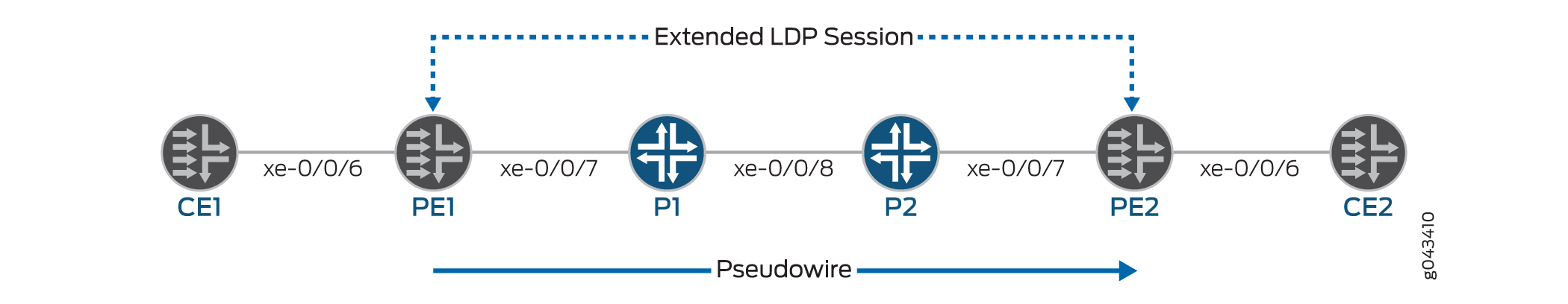
This topic refers to the local PE switch as PE1 and the remote PE switch as PE2. It also uses interface names rather than variables to help clarify the connections between the switches. The loopback addresses of the switches are configured as follows:
-
PE1: 10.127.1.1
-
PE2: 10.127.1.2
On QFX Series and EX4600 switches, the Layer 2 circuit CE facing interface does not support AE interfaces.
Configuring the Local PE Switch for Port-Based Layer 2 Circuit (Pseudo-wire)
Configure MPLS networks with an MTU (maximum transmission unit) that is at least 12 bytes larger than the largest frame size that will be transported by the LSPs. If the size of a encapsulated packet on the ingress LSR exceeds the LSP MTU, that packet is dropped. If an egress LSR receives a packet on a VC LSP with a length (after the label stack and sequencing control word have been popped) that exceeds the MTU of the destination layer 2 interface, that packet is also dropped.
To configure the local PE switch (PE1) for a port-based layer 2 circuit (pseudo-wire):
Configuring the Remote PE Switch for Port-Based Layer 2 Circuit (Pseudo-wire)
To configure the remote PE switch (PE2) for a port-based layer 2 circuit:
Configuring the Local PE Switch for VLAN-Based Layer 2 Circuit
To configure the local PE switch (PE1) for a VLAN-based layer 2 circuit:
Configuring the Remote PE Switch for VLAN-Based Layer 2 Circuit
To configure the remote PE switch (PE2) for a VLAN-based layer 2 circuit:
Change History Table
Feature support is determined by the platform and release you are using. Use Feature Explorer to determine if a feature is supported on your platform.