Example: Configuring Multiple-Instance LDP
The primary LDP instance is configured at the [edit protocols] hierarchy
level.
You can configure a specific instance of LDP by using the ldp statement
at the [edit routing-instances routing-instance-name
protocols] hierarchy level. This creates an instance of LDP for the
particular VRF routing instance. You must specify all the required VRF statements and
apply export and import policies to your LDP instance for the configuration to commit
properly.
Most of the LDP hierarchy levels available in a primary instance are also available for
specific instances of LDP. However, the no-forwarding option does not
work in a VRF-based instance of LDP.
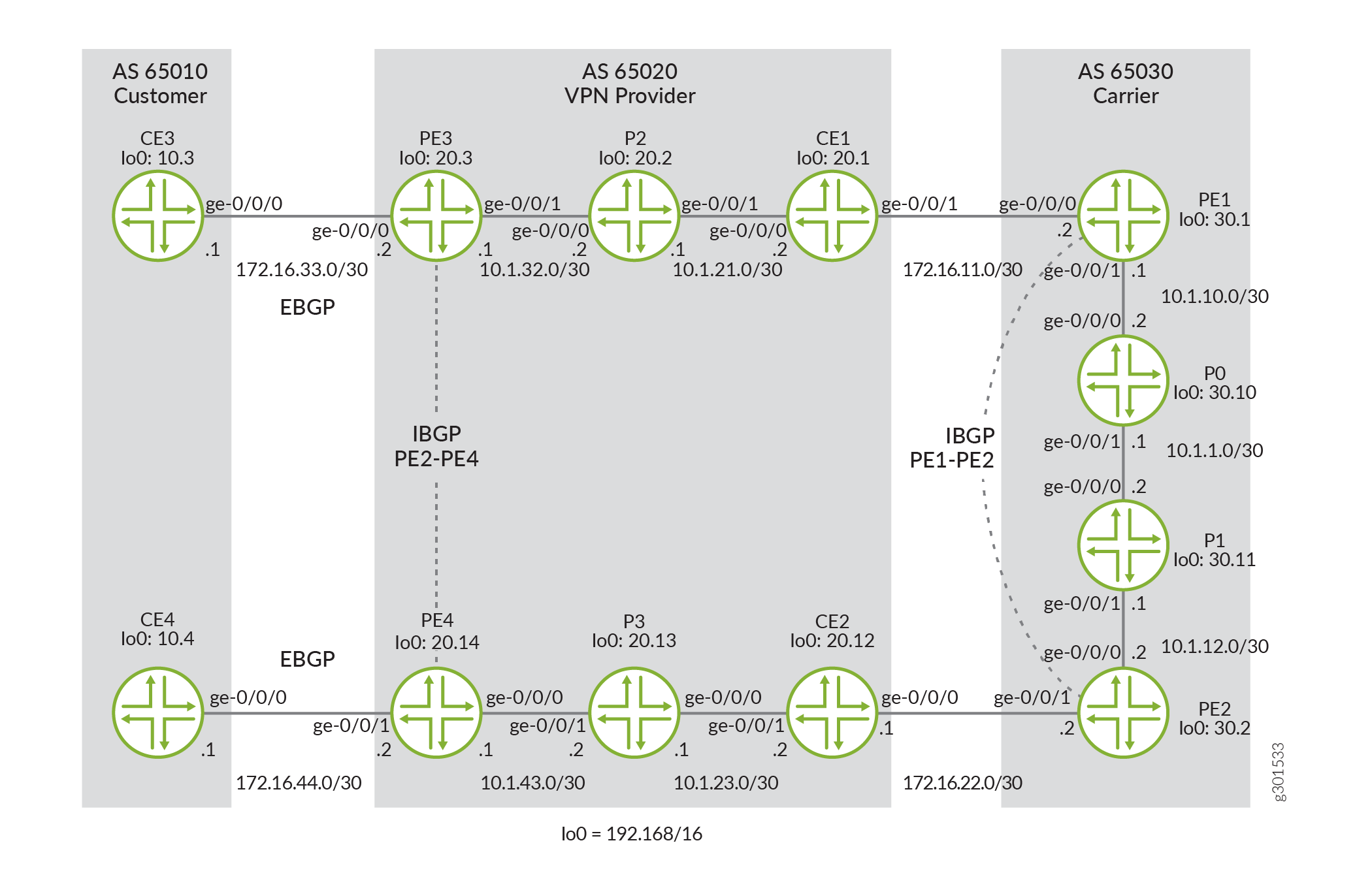
Figure 1 shows an example of a carrier-of-carriers network. CE3 and CE4 are end customer CE routers residing in AS 65010. The VPN provider in AS 65020 has three types of routers: PE3 and PE4 are PE routers that connect to the end customer, CE1 and CE2 act as the intermediate carrier CE routers, and P2 and P3 are internal transit routers. PE1 and PE2 in AS 65030 are PE routers servicing the intermediate VPN provider, and P0 and P1 are transit routers for the top-tier carrier.
To make this configuration work, you must complete three major tasks:
-
Configure external BGP between the VPN customer CE and the VPN provider PE.
-
Configure internal BGP using the VPN family between both pairs of PE routers (one IBGP connection between PE1 and PE2 and a second IBGP connection between Router PE3 and Router PE4).
-
Establish LDP and Interior Gateway Protocol (IGP) connections on all remaining links. This example uses OSPF as the IGP, but you can use the IGP of your choice.
Information supporting this carrier-of-carriers multiple-instance LDP example is summarized in Table 1.
|
Connection |
Protocols |
|---|---|
|
CE3 - PE3 |
EBGP family inet |
|
PE3 - P2 - CE1 |
OSPF and LDP |
|
CE1 - PE1 |
OSPF and LDP |
|
PE1 - P0 - P1 - PE2 |
OSPF and LDP |
|
PE1 - PE2 |
IBGP family inet-vpn |
|
PE2 - CE2 |
OSPF and LDP |
|
CE2 - P3 - PE4 |
OSPF and LDP |
|
PE4 - CE4 |
EBGP family inet |
|
PE3 - PE4 |
IBGP family inet-vpn |
Your configuration tasks start at Router CE3 and move router by router through the first part of the VPN provider network, into the carrier AS, through the second VPN provider cluster of AS 65020, and end at the second VPN customer Router CE4.
Since Router CE3 is the first customer router, configure EBGP between Router CE3 and the connected VPN provider Router PE3. You must also advertise your loopback address into BGP with a routing policy to allow IP reachability with Router CE4.
Router CE3
user@CE3#
set interfaces ge-0/0/0 description to-PE3
set interfaces ge-0/0/0 unit 0 family inet address 172.16.33.1/30
set interfaces lo0 unit 0 family inet address 192.168.10.3/32
set policy-options policy-statement loopback term 1 from route-filter 192.168.10.3/32 exact
set policy-options policy-statement loopback term 1 then accept
set policy-options policy-statement loopback term 3 then reject
set protocols bgp group to-PE3 export loopback
set protocols bgp group to-PE3 peer-as 65020
set protocols bgp group to-PE3 neighbor 172.16.33.2
set routing-options router-id 192.168.10.3
set routing-options autonomous-system 65010
On Router PE3, the configuration tasks are more involved. You need to complete the EBGP connection to Router CE3 in a VRF instance, enable MPLS and LDP on the interface pointing toward the VPN provider Router CE1, and configure a primary instance of IBGP to reach Router PE4 at the far edge of AS 65020.
Finally, set up an outbound VRF policy that places all BGP traffic and directly connected interfaces into a BGP community and an inbound VRF policy that accepts similar BGP community traffic from Router PE4.
Router PE3
user@PE3#
set interfaces ge-0/0/0 description to-CE3
set interfaces ge-0/0/0 unit 0 family inet address 172.16.33.2/30
set interfaces ge-0/0/0 unit 0 family mpls
set interfaces ge-0/0/1 description to-P2
set interfaces ge-0/0/1 unit 0 family inet address 10.1.32.1/30
set interfaces ge-0/0/1 unit 0 family mpls
set interfaces lo0 unit 0 family inet address 192.168.20.3/32
set policy-options policy-statement vpn-customer-export term 1 from protocol bgp
set policy-options policy-statement vpn-customer-export term 1 from protocol direct
set policy-options policy-statement vpn-customer-export term 1 then community add vpn-customer-comm
set policy-options policy-statement vpn-customer-export term 1 then accept
set policy-options policy-statement vpn-customer-export term 2 then reject
set policy-options policy-statement vpn-customer-import term 1 from protocol bgp
set policy-options policy-statement vpn-customer-import term 1 from community vpn-customer-comm
set policy-options policy-statement vpn-customer-import term 1 then accept
set policy-options policy-statement vpn-customer-import term 2 then reject
set policy-options community vpn-customer-comm members target:65020:1
set routing-instances vpn-customer instance-type vrf
set routing-instances vpn-customer protocols bgp group customer peer-as 65010
set routing-instances vpn-customer protocols bgp group customer as-override
set routing-instances vpn-customer protocols bgp group customer neighbor 172.16.33.1
set routing-instances vpn-customer interface ge-0/0/0.0
set routing-instances vpn-customer route-distinguisher 192.168.20.3:1
set routing-instances vpn-customer vrf-import vpn-customer-import
set routing-instances vpn-customer vrf-export vpn-customer-export
set protocols bgp group to-PE4 type internal
set protocols bgp group to-PE4 local-address 192.168.20.3
set protocols bgp group to-PE4 neighbor 192.168.20.14 family inet-vpn unicast
set protocols ldp interface ge-0/0/1.0
set protocols mpls interface ge-0/0/1.0
set protocols ospf area 0.0.0.0 interface ge-0/0/1.0
set protocols ospf area 0.0.0.0 interface lo0.0
set routing-options router-id 192.168.20.3
set routing-options autonomous-system 65020
On Router P2, enable LDP and the IGP used for transporting labels (in this case, OSPF). You will repeat these tasks on all transit core routers, both in the VPN provider network and the core carrier network.
Router P2
user@P2#
set interfaces ge-0/0/0 description to-PE3
set interfaces ge-0/0/0 unit 0 family inet address 10.1.32.2/30
set interfaces ge-0/0/0 unit 0 family mpls
set interfaces ge-0/0/1 description to-CE1
set interfaces ge-0/0/1 unit 0 family inet address 10.1.21.1/30
set interfaces ge-0/0/1 unit 0 family mpls
set interfaces lo0 unit 0 family inet address 192.168.20.2/32
set protocols ldp interface ge-0/0/0.0
set protocols ldp interface ge-0/0/1.0
set protocols ospf area 0.0.0.0 interface ge-0/0/0.0
set protocols ospf area 0.0.0.0 interface ge-0/0/1.0
set protocols ospf area 0.0.0.0 interface lo0.0
set routing-options router-id 192.168.20.2
set routing-options autonomous-system 65020
For Router CE1, configure LDP and OSPF in the same manner that you configured Router P2.
Router CE1
user@CE1#
set interfaces ge-0/0/0 description to-P2
set interfaces ge-0/0/0 unit 0 family inet address 10.1.21.2/30
set interfaces ge-0/0/0 unit 0 family mpls
set interfaces ge-0/0/1 description to-PE1
set interfaces ge-0/0/1 unit 0 family inet address 172.16.11.1/30
set interfaces ge-0/0/1 unit 0 family mpls
set interfaces lo0 unit 0 family inet address 192.168.20.1/32
set protocols ldp interface ge-0/0/0.0
set protocols ldp interface ge-0/0/1.0
set protocols ospf area 0.0.0.0 interface ge-0/0/0.0
set protocols ospf area 0.0.0.0 interface ge-0/0/1.0
set protocols ospf area 0.0.0.0 interface lo0.0
set routing-options router-id 192.168.20.1
set routing-options autonomous-system 65020
On core carrier Router PE1, configure a primary instance for OSPF, LDP, MPLS, and IBGP
(with the family inet-vpn option) to connect the router to neighbor
Router PE2. Next, implement multiple-instance LDP by establishing a secondary instance.
Enable LDP and OSPF in this instance for Router PE1 to communicate with Router CE1. MPLS
is not required in the secondary instance.
Finally, set up an outbound VRF policy that places all LDP traffic coming from Router CE1 into a BGP community, an export policy that sends this community traffic to Router PE2, and an inbound VRF policy that accepts similar BGP community traffic from Router PE2. This step tunnels the VPN provider’s LDP traffic into the carrier’s BGP session.
Router PE1
user@PE1#
set interfaces ge-0/0/0 description to-CE1
set interfaces ge-0/0/0 unit 0 family inet address 172.16.11.2/30
set interfaces ge-0/0/0 unit 0 family mpls
set interfaces ge-0/0/1 description to-P0
set interfaces ge-0/0/1 unit 0 family inet address 10.1.10.1/30
set interfaces ge-0/0/1 unit 0 family mpls
set interfaces lo0 unit 0 family inet address 192.168.30.1/32
set policy-options policy-statement bgp-routes-export term 1 from protocol bgp
set policy-options policy-statement bgp-routes-export term 1 from community vpn-provider-comm
set policy-options policy-statement bgp-routes-export term 1 then accept
set policy-options policy-statement bgp-routes-export term 2 then reject
set policy-options policy-statement vpn-provider-export term 1 from protocol ldp
set policy-options policy-statement vpn-provider-export term 1 from protocol ospf
set policy-options policy-statement vpn-provider-export term 1 then community add vpn-provider-comm
set policy-options policy-statement vpn-provider-export term 1 then accept
set policy-options policy-statement vpn-provider-export term 2 then reject
set policy-options policy-statement vpn-provider-import term 1 from protocol bgp
set policy-options policy-statement vpn-provider-import term 1 from community vpn-provider-comm
set policy-options policy-statement vpn-provider-import term 1 then accept
set policy-options policy-statement vpn-provider-import term 2 then reject
set policy-options community vpn-provider-comm members target:65030:1
set routing-instances vpn-provider instance-type vrf
set routing-instances vpn-provider protocols ldp egress-policy bgp-routes-export
set routing-instances vpn-provider protocols ldp interface ge-0/0/0.0
set routing-instances vpn-provider protocols mpls traffic-engineering bgp-igp
set routing-instances vpn-provider protocols mpls interface ge-0/0/0.0
set routing-instances vpn-provider protocols ospf area 0.0.0.0 interface ge-0/0/0.0
set routing-instances vpn-provider protocols ospf export bgp-routes-export
set routing-instances vpn-provider interface ge-0/0/0.0
set routing-instances vpn-provider route-distinguisher 192.168.30.1:1
set routing-instances vpn-provider vrf-import vpn-provider-import
set routing-instances vpn-provider vrf-export vpn-provider-export
set protocols bgp group pe type internal
set protocols bgp group pe local-address 192.168.30.1
set protocols bgp group pe family inet-vpn unicast
set protocols bgp group pe neighbor 192.168.30.2
set protocols ldp interface ge-0/0/1.0
set protocols ospf area 0.0.0.0 interface lo0.0
set protocols ospf area 0.0.0.0 interface ge-0/0/1.0
set routing-options router-id 192.168.30.1
set routing-options autonomous-system 65030
On Router P0, enable LDP and OSPF in the same manner that you configured these protocols on Router P2. You will repeat these tasks on Router P1 and Router P3.
Router P0
user@P0#
set interfaces ge-0/0/0 description to-PE1
set interfaces ge-0/0/0 unit 0 family inet address 10.1.10.2/30
set interfaces ge-0/0/0 unit 0 family mpls
set interfaces ge-0/0/1 description to-P1
set interfaces ge-0/0/1 unit 0 family inet address 10.1.1.1/30
set interfaces ge-0/0/1 unit 0 family mpls
set interfaces lo0 unit 0 family inet address 192.168.30.10/32
set protocols ldp interface ge-0/0/0.0
set protocols ldp interface ge-0/0/1.0
set protocols ospf area 0.0.0.0 interface ge-0/0/0.0
set protocols ospf area 0.0.0.0 interface ge-0/0/1.0
set protocols ospf area 0.0.0.0 interface lo0.0
set routing-options router-id 192.168.30.10
set routing-options autonomous-system 65030
On Router P1, enable LDP and the IGP used for transporting labels (OSPF in this case).
Router P1
user@P1#
set interfaces ge-0/0/0 description to-P0
set interfaces ge-0/0/0 unit 0 family inet address 10.1.1.2/30
set interfaces ge-0/0/0 unit 0 family mpls
set interfaces ge-0/0/1 description to-PE2
set interfaces ge-0/0/1 unit 0 family inet address 10.1.12.1/30
set interfaces ge-0/0/1 unit 0 family mpls
set interfaces lo0 unit 0 family inet address 192.168.30.11/32
set protocols ldp interface ge-0/0/0.0
set protocols ldp interface ge-0/0/1.0
set protocols ospf area 0.0.0.0 interface ge-0/0/0.0
set protocols ospf area 0.0.0.0 interface ge-0/0/1.0
set protocols ospf area 0.0.0.0 interface lo0.0
set routing-options router-id 192.168.30.11
set routing-options autonomous-system 65030
Core carrier Router PE2 is a mirror image of Router PE1. First, configure a primary
instance for OSPF, LDP, MPLS, and IBGP (with the family inet-vpn
option) to connect Router PE2 to neighbor Router PE1. Next, implement multiple-instance
LDP by establishing a secondary instance. Enable LDP and OSPF in this instance for
Router PE2 to communicate with Router CE2. MPLS is not required in the secondary
instance.
Finally, set up an outbound VRF policy that places all LDP traffic coming from Router CE2 into a BGP community, an export policy that sends this community traffic to Router PE1, and an inbound VRF policy that accepts similar BGP community traffic from Router PE1. This step tunnels the VPN provider’s LDP traffic into the carrier’s BGP session.
Router PE2
user@PE2#
set interfaces ge-0/0/0 description to-P1
set interfaces ge-0/0/0 unit 0 family inet address 10.1.12.2/30
set interfaces ge-0/0/0 unit 0 family mpls
set interfaces ge-0/0/1 description to-CE2
set interfaces ge-0/0/1 unit 0 family inet address 172.16.22.2/30
set interfaces ge-0/0/1 unit 0 family mpls
set interfaces lo0 unit 0 family inet address 192.168.30.2/32
set policy-options policy-statement bgp-routes-export term 1 from protocol bgp
set policy-options policy-statement bgp-routes-export term 1 from community vpn-provider-comm
set policy-options policy-statement bgp-routes-export term 1 then accept
set policy-options policy-statement bgp-routes-export term 2 then reject
set policy-options policy-statement vpn-provider-export term 1 from protocol ldp
set policy-options policy-statement vpn-provider-export term 1 from protocol ospf
set policy-options policy-statement vpn-provider-export term 1 then community add vpn-provider-comm
set policy-options policy-statement vpn-provider-export term 1 then accept
set policy-options policy-statement vpn-provider-export term 2 then reject
set policy-options policy-statement vpn-provider-import term 1 from protocol bgp
set policy-options policy-statement vpn-provider-import term 1 from community vpn-provider-comm
set policy-options policy-statement vpn-provider-import term 1 then accept
set policy-options policy-statement vpn-provider-import term 2 then reject
set policy-options community vpn-provider-comm members target:65030:1
set routing-instances vpn-provider instance-type vrf
set routing-instances vpn-provider protocols ldp egress-policy bgp-routes-export
set routing-instances vpn-provider protocols ldp interface ge-0/0/1.0
set routing-instances vpn-provider protocols mpls traffic-engineering bgp-igp
set routing-instances vpn-provider protocols mpls interface ge-0/0/1.0
set routing-instances vpn-provider protocols ospf area 0.0.0.0 interface ge-0/0/1.0
set routing-instances vpn-provider protocols ospf export bgp-routes-export
set routing-instances vpn-provider interface ge-0/0/1.0
set routing-instances vpn-provider route-distinguisher 192.168.30.2:1
set routing-instances vpn-provider vrf-import vpn-provider-import
set routing-instances vpn-provider vrf-export vpn-provider-export
set protocols bgp group pe type internal
set protocols bgp group pe local-address 192.168.30.2
set protocols bgp group pe family inet-vpn unicast
set protocols bgp group pe neighbor 192.168.30.1
set protocols ldp interface ge-0/0/0.0
set protocols ospf area 0.0.0.0 interface lo0.0
set protocols ospf area 0.0.0.0 interface ge-0/0/0.0
set routing-options router-id 192.168.30.2
set routing-options autonomous-system 65030
For Router CE2, configure LDP and OSPF as you did on Router CE1 and the transit P routers.
Router CE2
user@CE2#
set interfaces ge-0/0/0 description to-PE2
set interfaces ge-0/0/0 unit 0 family inet address 172.16.22.1/30
set interfaces ge-0/0/0 unit 0 family mpls
set interfaces ge-0/0/1 description to-P3
set interfaces ge-0/0/1 unit 0 family inet address 10.1.23.2/30
set interfaces ge-0/0/1 unit 0 family mpls
set interfaces lo0 unit 0 family inet address 192.168.20.12/32
set protocols ldp interface ge-0/0/0.0
set protocols ldp interface ge-0/0/1.0
set protocols ospf area 0.0.0.0 interface ge-0/0/0.0
set protocols ospf area 0.0.0.0 interface ge-0/0/1.0
set protocols ospf area 0.0.0.0 interface lo0.0
set routing-options router-id 192.168.20.12
set routing-options autonomous-system 65020
Since Router P3 is another core provider router, enable LDP and OSPF on all transit interfaces.
Router P3
user@P3#
set interfaces ge-0/0/0 description to-CE2
set interfaces ge-0/0/0 unit 0 family inet address 10.1.23.1/30
set interfaces ge-0/0/0 unit 0 family mpls
set interfaces ge-0/0/1 description to-PE4
set interfaces ge-0/0/1 unit 0 family inet address 10.1.43.2/30
set interfaces ge-0/0/1 unit 0 family mpls
set interfaces lo0 unit 0 family inet address 192.168.20.13/32
set protocols ldp interface ge-0/0/0.0
set protocols ldp interface ge-0/0/1.0
set protocols ospf area 0.0.0.0 interface ge-0/0/0.0
set protocols ospf area 0.0.0.0 interface ge-0/0/1.0
set protocols ospf area 0.0.0.0 interface lo0.0
set routing-options router-id 192.168.20.13
set routing-options autonomous-system 65020
On Router PE4, complete the IBGP connection initiated on Router PE3 to connect the edge routers in AS 65020. Also, enable LDP and MPLS on the interface pointing toward the VPN provider Router CE2 and establish an EBGP connection to Router CE4 through use of a VRF instance.
Finally, set up an outbound VRF policy that places all BGP traffic and directly connected interfaces into a BGP community and an inbound VRF policy that accepts similar BGP community traffic from Router PE3.
Router PE4
user@PE4#
set interfaces ge-0/0/0 description to-P3
set interfaces ge-0/0/0 unit 0 family inet address 10.1.43.1/30
set interfaces ge-0/0/0 unit 0 family mpls
set interfaces ge-0/0/1 description to-CE4
set interfaces ge-0/0/1 unit 0 family inet address 172.16.44.2/30
set interfaces ge-0/0/1 unit 0 family mpls
set interfaces lo0 unit 0 family inet address 192.168.20.14/32
set policy-options policy-statement vpn-customer-export term 1 from protocol bgp
set policy-options policy-statement vpn-customer-export term 1 from protocol direct
set policy-options policy-statement vpn-customer-export term 1 then community add vpn-customer-comm
set policy-options policy-statement vpn-customer-export term 1 then accept
set policy-options policy-statement vpn-customer-export term 2 then reject
set policy-options policy-statement vpn-customer-import term 1 from protocol bgp
set policy-options policy-statement vpn-customer-import term 1 from community vpn-customer-comm
set policy-options policy-statement vpn-customer-import term 1 then accept
set policy-options policy-statement vpn-customer-import term 2 then reject
set policy-options community vpn-customer-comm members target:65020:1
set routing-instances vpn-customer instance-type vrf
set routing-instances vpn-customer protocols bgp group customer peer-as 65010
set routing-instances vpn-customer protocols bgp group customer as-override
set routing-instances vpn-customer protocols bgp group customer neighbor 172.16.44.1
set routing-instances vpn-customer interface ge-0/0/1.0
set routing-instances vpn-customer route-distinguisher 192.168.20.14:1
set routing-instances vpn-customer vrf-import vpn-customer-import
set routing-instances vpn-customer vrf-export vpn-customer-export
set protocols bgp group int type internal
set protocols bgp group int local-address 192.168.20.14
set protocols bgp group int neighbor 192.168.20.3 family inet-vpn unicast
set protocols ldp interface ge-0/0/0.0
set protocols mpls interface ge-0/0/0.0
set protocols ospf area 0.0.0.0 interface ge-0/0/0.0
set protocols ospf area 0.0.0.0 interface lo0.0
set routing-options router-id 192.168.20.14
set routing-options autonomous-system 65020
Router CE4 is the destination VPN customer router. Configure EBGP between Router CE4 and the connected VPN provider Router PE4 to complete the configuration. Remember to advertise the loopback address into BGP by using a routing policy to allow IP reachability with Router CE3.
Router CE4
user@CE4#
set interfaces ge-0/0/0 description to-PE4
set interfaces ge-0/0/0 unit 0 family inet address 172.16.44.1/30
set interfaces lo0 unit 0 family inet address 192.168.10.4/32
set policy-options policy-statement loopback term 1 from route-filter 192.168.10.4/32 exact
set policy-options policy-statement loopback term 1 then accept
set policy-options policy-statement loopback term 3 then reject
set protocols bgp group provider export loopback
set protocols bgp group provider peer-as 65020
set protocols bgp group provider neighbor 172.16.44.2
set routing-options router-id 192.168.10.4
set routing-options autonomous-system 65010
Verifying Your Work
To verify the proper operation of your multiple-instance LDP configuration, use the following commands:
-
show ldp database -
show ldp interface -
show ldp neighbor -
show ldp path -
show ldp route -
show ldp session -
show ldp statistics
The display output for these commands is the same as in previous Junos OS Releases, except for one difference. An instance name can now be used as an argument.
If you include an instance name with these commands, you display information for the
specified LDP instance. For example, the command show ldp neighbor instance
crockett shows all the LDP neighbors for a VRF instance named
crockett. Conversely, show ldp neighbor
without an instance name displays the LDP neighbors associated with the primary
instance.
The following sections show the output of these commands used with the configuration example:
- Router CE3 Status
- Router PE3 Status
- Router CE1 Status
- Router PE1 Status
- Router PE2 Status
- Router CE2 Status
- Router PE4 Status
- Router CE4 Status
Router CE3 Status
user@CE3> show bgp summary
Threading mode: BGP I/O
Default eBGP mode: advertise - accept, receive - accept
Groups: 1 Peers: 1 Down peers: 0
Table          Tot Paths  Act Paths Suppressed    History Damp State    Pending
inet.0
                       2          2          0          0          0          0
Peer                     AS      InPkt     OutPkt    OutQ   Flaps Last Up/Dwn State|#Active/Received/Accepted/Damped...
172.16.33.2           65020      19653      19724       0       0  6d 3:53:37 Establ
  inet.0: 2/2/2/0

user@CE3>  show route protocol bgp
inet.0: 11 destinations, 11 routes (11 active, 0 holddown, 0 hidden)
+ = Active Route, - = Last Active, * = Both

172.16.44.0/30     *[BGP/170] 6d 00:53:43, localpref 100
                      AS path: 65020 I, validation-state: unverified
                    >  to 172.16.33.2 via ge-0/0/0.0
192.168.10.4/32    *[BGP/170] 6d 00:53:42, localpref 100
                      AS path: 65020 65020 I, validation-state: unverified
                    >  to 172.16.33.2 via ge-0/0/0.0

inet6.0: 1 destinations, 1 routes (1 active, 0 holddown, 0 hidden)

user@CE3>  ping 192.168.10.4 source 192.168.10.3 count 2
PING 192.168.10.4 (192.168.10.4): 56 data bytes
64 bytes from 192.168.10.4: icmp_seq=0 ttl=54 time=24.744 ms
64 bytes from 192.168.10.4: icmp_seq=1 ttl=54 time=16.336 ms

--- 192.168.10.4 ping statistics ---
2 packets transmitted, 2 packets received, 0% packet loss
round-trip min/avg/max/stddev = 16.336/20.540/24.744/4.204 ms
Router PE3 Status
user@PE3> show bgp summary
Threading mode: BGP I/O
Default eBGP mode: advertise - accept, receive - accept
Groups: 2 Peers: 2 Down peers: 0
Table          Tot Paths  Act Paths Suppressed    History Damp State    Pending
bgp.l3vpn.0
                       2          2          0          0          0          0
Peer                     AS      InPkt     OutPkt    OutQ   Flaps Last Up/Dwn State|#Active/Received/Accepted/Damped...
172.16.33.1           65010      19783      19708       0       0  6d 4:19:07 Establ
  vpn-customer.inet.0: 1/1/1/0
192.168.20.14         65020      19299      19297       0       1  6d 1:17:05 Establ
  bgp.l3vpn.0: 2/2/2/0
  vpn-customer.inet.0: 2/2/2/0

user@PE3>  show route protocol ldp
inet.0: 20 destinations, 20 routes (20 active, 0 holddown, 0 hidden)
+ = Active Route, - = Last Active, * = Both

224.0.0.2/32       *[LDP/9] 6d 04:55:21, metric 1
                       MultiRecv

inet.3: 7 destinations, 7 routes (7 active, 0 holddown, 0 hidden)
+ = Active Route, - = Last Active, * = Both

10.1.23.0/30       *[LDP/9] 6d 01:18:46, metric 1
                    >  to 10.1.32.2 via ge-0/0/1.0, Push 299968
10.1.43.0/30       *[LDP/9] 6d 01:18:46, metric 1
                    >  to 10.1.32.2 via ge-0/0/1.0, Push 300000
192.168.20.1/32    *[LDP/9] 6d 01:18:46, metric 1
                    >  to 10.1.32.2 via ge-0/0/1.0, Push 299952
192.168.20.2/32    *[LDP/9] 6d 04:22:00, metric 1
                    >  to 10.1.32.2 via ge-0/0/1.0
192.168.20.12/32   *[LDP/9] 6d 01:18:46, metric 1
                    >  to 10.1.32.2 via ge-0/0/1.0, Push 299984
192.168.20.13/32   *[LDP/9] 6d 01:18:46, metric 1
                    >  to 10.1.32.2 via ge-0/0/1.0, Push 300016
192.168.20.14/32   *[LDP/9] 6d 01:18:46, metric 1
                    >  to 10.1.32.2 via ge-0/0/1.0, Push 300032

vpn-customer.inet.0: 5 destinations, 5 routes (5 active, 0 holddown, 0 hidden)

mpls.0: 13 destinations, 13 routes (13 active, 0 holddown, 0 hidden)
+ = Active Route, - = Last Active, * = Both

299856             *[LDP/9] 6d 04:22:00, metric 1
                    >  to 10.1.32.2 via ge-0/0/1.0, Pop
299856(S=0)        *[LDP/9] 6d 04:22:00, metric 1
                    >  to 10.1.32.2 via ge-0/0/1.0, Pop
299984             *[LDP/9] 6d 01:18:46, metric 1
                    >  to 10.1.32.2 via ge-0/0/1.0, Swap 299952
300000             *[LDP/9] 6d 01:18:46, metric 1
                    >  to 10.1.32.2 via ge-0/0/1.0, Swap 299968
300016             *[LDP/9] 6d 01:18:46, metric 1
                    >  to 10.1.32.2 via ge-0/0/1.0, Swap 299984
300032             *[LDP/9] 6d 01:18:46, metric 1
                    >  to 10.1.32.2 via ge-0/0/1.0, Swap 300000
300048             *[LDP/9] 6d 01:18:46, metric 1
                    >  to 10.1.32.2 via ge-0/0/1.0, Swap 300016
300064             *[LDP/9] 6d 01:18:46, metric 1
                    >  to 10.1.32.2 via ge-0/0/1.0, Swap 300032

bgp.l3vpn.0: 2 destinations, 2 routes (2 active, 0 holddown, 0 hidden)

inet6.0: 1 destinations, 1 routes (1 active, 0 holddown, 0 hidden)

vpn-customer.inet6.0: 1 destinations, 1 routes (1 active, 0 holddown, 0 hidden)

user@PE3>  show route protocol bgp
inet.0: 20 destinations, 20 routes (20 active, 0 holddown, 0 hidden)

inet.3: 7 destinations, 7 routes (7 active, 0 holddown, 0 hidden)

vpn-customer.inet.0: 5 destinations, 5 routes (5 active, 0 holddown, 0 hidden)
+ = Active Route, - = Last Active, * = Both

172.16.44.0/30     *[BGP/170] 6d 01:19:31, localpref 100, from 192.168.20.14
                      AS path: I, validation-state: unverified
                    >  to 10.1.32.2 via ge-0/0/1.0, Push 299968, Push 300032(top)
192.168.10.3/32    *[BGP/170] 6d 04:21:33, localpref 100
                      AS path: 65010 I, validation-state: unverified
                    >  to 172.16.33.1 via ge-0/0/0.0
192.168.10.4/32    *[BGP/170] 6d 01:19:30, localpref 100, from 192.168.20.14
                      AS path: 65010 I, validation-state: unverified
                    >  to 10.1.32.2 via ge-0/0/1.0, Push 299968, Push 300032(top)

mpls.0: 13 destinations, 13 routes (13 active, 0 holddown, 0 hidden)

bgp.l3vpn.0: 2 destinations, 2 routes (2 active, 0 holddown, 0 hidden)
+ = Active Route, - = Last Active, * = Both

192.168.20.14:1:172.16.44.0/30
                   *[BGP/170] 6d 01:19:31, localpref 100, from 192.168.20.14
                      AS path: I, validation-state: unverified
                    >  to 10.1.32.2 via ge-0/0/1.0, Push 299968, Push 300032(top)
192.168.20.14:1:192.168.10.4/32
                   *[BGP/170] 6d 01:19:30, localpref 100, from 192.168.20.14
                      AS path: 65010 I, validation-state: unverified
                    >  to 10.1.32.2 via ge-0/0/1.0, Push 299968, Push 300032(top)

inet6.0: 1 destinations, 1 routes (1 active, 0 holddown, 0 hidden)

vpn-customer.inet6.0: 1 destinations, 1 routes (1 active, 0 holddown, 0 hidden)
Router CE1 Status
user@CE1> show ldp neighbor
Address                             Interface       Label space ID     Hold time
172.16.11.2                         ge-0/0/1.0      172.16.11.2:0        12
10.1.21.1                           ge-0/0/0.0      192.168.20.2:0       12

user@CE1>  show route
inet.0: 15 destinations, 15 routes (15 active, 0 holddown, 0 hidden)
+ = Active Route, - = Last Active, * = Both

10.1.21.0/30       *[Direct/0] 6d 01:32:24
                    >  via ge-0/0/0.0
10.1.21.2/32       *[Local/0] 6d 01:32:24
                       Local via ge-0/0/0.0
10.1.23.0/30       *[OSPF/10] 6d 03:34:28, metric 3
                    >  to 172.16.11.2 via ge-0/0/1.0
10.1.32.0/30       *[OSPF/10] 6d 01:31:41, metric 2
                    >  to 10.1.21.1 via ge-0/0/0.0
10.1.43.0/30       *[OSPF/10] 6d 03:28:49, metric 4
                    >  to 172.16.11.2 via ge-0/0/1.0
172.16.11.0/30     *[Direct/0] 6d 04:57:56
                    >  via ge-0/0/1.0
172.16.11.1/32     *[Local/0] 6d 04:57:56
                       Local via ge-0/0/1.0
192.168.20.1/32    *[Direct/0] 6d 04:40:45
                    >  via lo0.0
192.168.20.2/32    *[OSPF/10] 6d 01:31:41, metric 1
                    >  to 10.1.21.1 via ge-0/0/0.0
192.168.20.3/32    *[OSPF/10] 6d 01:31:41, metric 2
                    >  to 10.1.21.1 via ge-0/0/0.0
192.168.20.12/32   *[OSPF/150] 6d 03:34:27, metric 1, tag 3489725958
                    >  to 172.16.11.2 via ge-0/0/1.0
192.168.20.13/32   *[OSPF/150] 6d 03:28:46, metric 1, tag 3489725958
                    >  to 172.16.11.2 via ge-0/0/1.0
192.168.20.14/32   *[OSPF/150] 6d 02:51:40, metric 1, tag 3489725958
                    >  to 172.16.11.2 via ge-0/0/1.0
224.0.0.2/32       *[LDP/9] 6d 04:57:56, metric 1
                       MultiRecv
224.0.0.5/32       *[OSPF/10] 6d 04:57:56, metric 1
                       MultiRecv

inet.3: 7 destinations, 7 routes (7 active, 0 holddown, 0 hidden)
+ = Active Route, - = Last Active, * = Both

10.1.23.0/30       *[LDP/9] 6d 01:32:49, metric 1
                    >  to 172.16.11.2 via ge-0/0/1.0, Push 300032
10.1.43.0/30       *[LDP/9] 6d 01:32:49, metric 1
                    >  to 172.16.11.2 via ge-0/0/1.0, Push 300064
192.168.20.2/32    *[LDP/9] 6d 01:31:39, metric 1
                    >  to 10.1.21.1 via ge-0/0/0.0
192.168.20.3/32    *[LDP/9] 6d 01:31:39, metric 1
                    >  to 10.1.21.1 via ge-0/0/0.0, Push 299856
192.168.20.12/32   *[LDP/9] 6d 01:32:49, metric 1
                    >  to 172.16.11.2 via ge-0/0/1.0, Push 300048
192.168.20.13/32   *[LDP/9] 6d 01:32:49, metric 1
                    >  to 172.16.11.2 via ge-0/0/1.0, Push 300080
192.168.20.14/32   *[LDP/9] 6d 01:32:49, metric 1
                    >  to 172.16.11.2 via ge-0/0/1.0, Push 300096

mpls.0: 8 destinations, 8 routes (8 active, 0 holddown, 0 hidden)
+ = Active Route, - = Last Active, * = Both

299888             *[LDP/9] 6d 01:32:49, metric 1
                    >  to 172.16.11.2 via ge-0/0/1.0, Swap 300032
299904             *[LDP/9] 6d 01:32:49, metric 1
                    >  to 172.16.11.2 via ge-0/0/1.0, Swap 300048
299920             *[LDP/9] 6d 01:32:49, metric 1
                    >  to 172.16.11.2 via ge-0/0/1.0, Swap 300064
299936             *[LDP/9] 6d 01:32:49, metric 1
                    >  to 172.16.11.2 via ge-0/0/1.0, Swap 300080
299952             *[LDP/9] 6d 01:32:49, metric 1
                    >  to 172.16.11.2 via ge-0/0/1.0, Swap 300096
299968             *[LDP/9] 6d 01:31:39, metric 1
                    >  to 10.1.21.1 via ge-0/0/0.0, Pop
299968(S=0)        *[LDP/9] 6d 01:31:39, metric 1
                    >  to 10.1.21.1 via ge-0/0/0.0, Pop
299984             *[LDP/9] 6d 01:31:39, metric 1
                    >  to 10.1.21.1 via ge-0/0/0.0, Swap 299856

inet6.0: 1 destinations, 1 routes (1 active, 0 holddown, 0 hidden)
+ = Active Route, - = Last Active, * = Both

ff02::2/128        *[INET6/0] 1w0d 02:45:00
                       MultiRecv
Router PE1 Status
user@PE1> show ldp neighbor instance vpn-provider
Address                             Interface       Label space ID     Hold time
172.16.11.1                         ge-0/0/0.0      192.168.20.1:0       14

user@PE1>  show ldp database instance vpn-provider
Input label database, 172.16.11.2:0--192.168.20.1:0
Labels received: 8
  Label     Prefix
 299888      10.1.23.0/30
 299920      10.1.43.0/30
      3      192.168.20.1/32
 299968      192.168.20.2/32
 299984      192.168.20.3/32
 299904      192.168.20.12/32
 299936      192.168.20.13/32
 299952      192.168.20.14/32

Output label database, 172.16.11.2:0--192.168.20.1:0
Labels advertised: 8
  Label     Prefix
 300032      10.1.23.0/30
 300064      10.1.43.0/30
 299824      192.168.20.1/32
 300112      192.168.20.2/32
 300128      192.168.20.3/32
 300048      192.168.20.12/32
 300080      192.168.20.13/32
 300096      192.168.20.14/32

user@PE1>  show ldp interface instance vpn-provider
Interface          Address                          Label space ID   Nbr   Next
                                                                    count  hello
ge-0/0/0.0         172.16.11.2                      172.16.11.2:0     1      2

user@PE1>  show ldp path instance vpn-provider
Output Session (label)          Input Session (label)
192.168.20.1:0(299824)(                             ) 192.168.20.1:0(3)( )
  Attached route:  192.168.20.1/32, Ingress route
192.168.20.1:0(300032)          ( )
  Attached route:  10.1.23.0/30
192.168.20.1:0(300048)          ( )
  Attached route:  192.168.20.12/32
192.168.20.1:0(300064)          ( )
  Attached route:  10.1.43.0/30
192.168.20.1:0(300080)          ( )
  Attached route:  192.168.20.13/32
192.168.20.1:0(300096)          ( )
  Attached route:  192.168.20.14/32
192.168.20.1:0(300112)          192.168.20.1:0(299968)
  Attached route:  192.168.20.2/32, Ingress route
192.168.20.1:0(300128)          192.168.20.1:0(299984)
  Attached route:  192.168.20.3/32, Ingress route

user@PE1>  show ldp route instance vpn-provider
Destination                            Next-hop intf/lsp/table  Next-hop address
 10.1.21.0/30                          ge-0/0/0.0               172.16.11.1
 10.1.23.0/30                                                   192.168.30.2
 10.1.32.0/30                          ge-0/0/0.0               172.16.11.1
 10.1.43.0/30                                                   192.168.30.2
 172.16.11.0/30                        ge-0/0/0.0
 172.16.11.2/32
 192.168.20.1/32                       ge-0/0/0.0               172.16.11.1
 192.168.20.2/32                       ge-0/0/0.0               172.16.11.1
 192.168.20.3/32                       ge-0/0/0.0               172.16.11.1
 192.168.20.12/32                                               192.168.30.2
 192.168.20.13/32                                               192.168.30.2
 192.168.20.14/32                                               192.168.30.2
 224.0.0.5/32

user@PE1>  show ldp session instance vpn-provider
  Address                           State       Connection  Hold time  Adv. Mode
192.168.20.1                        Operational Open          21         DU

user@PE1>  show bgp summary
Threading mode: BGP I/O
Default eBGP mode: advertise - accept, receive - accept
Groups: 1 Peers: 1 Down peers: 0
Table          Tot Paths  Act Paths Suppressed    History Damp State    Pending
bgp.l3vpn.0
                       5          5          0          0          0          0
Peer                     AS      InPkt     OutPkt    OutQ   Flaps Last Up/Dwn State|#Active/Received/Accepted/Damped...
192.168.30.2          65030      19795      19797       0       0  6d 4:21:31 Establ
  bgp.l3vpn.0: 5/5/5/0
  vpn-provider.inet.0: 5/5/5/0
Router PE2 Status
user@PE2> show ldp neighbor instance vpn-provider
Address                             Interface       Label space ID     Hold time
172.16.22.1                         ge-0/0/1.0      192.168.20.12:0      12

user@PE2>  show ldp database instance vpn-provider
Input label database, 172.16.22.2:0--192.168.20.12:0
Labels received: 8
  Label     Prefix
 299888      10.1.21.0/30
 299904      10.1.32.0/30
 299808      192.168.20.1/32
 299920      192.168.20.2/32
 299936      192.168.20.3/32
      3      192.168.20.12/32
 299856      192.168.20.13/32
 299872      192.168.20.14/32

Output label database, 172.16.22.2:0--192.168.20.12:0
Labels advertised: 8
  Label     Prefix
 300000      10.1.21.0/30
 300032      10.1.32.0/30
 299888      192.168.20.1/32
 300016      192.168.20.2/32
 300048      192.168.20.3/32
 299920      192.168.20.12/32
 299952      192.168.20.13/32
 299984      192.168.20.14/32

user@PE2>  show ldp interface instance vpn-provider
Interface          Address                          Label space ID   Nbr   Next
                                                                    count  hello
ge-0/0/1.0         172.16.22.2                      172.16.22.2:0     1      4

user@PE2>  show ldp path instance vpn-provider
Output Session (label)          Input Session (label)
192.168.20.12:0(299888)(                             )( )
                                ( )
  Attached route:  192.168.20.1/32
192.168.20.12:0(299920)         192.168.20.12:0(3)
  Attached route:  192.168.20.12/32, Ingress route
192.168.20.12:0(299952)         192.168.20.12:0(299856)
  Attached route:  192.168.20.13/32, Ingress route
192.168.20.12:0(299984)         192.168.20.12:0(299872)
  Attached route:  192.168.20.14/32, Ingress route
192.168.20.12:0(300000)         ( )
  Attached route:  10.1.21.0/30
192.168.20.12:0(300016)         ( )
  Attached route:  192.168.20.2/32
192.168.20.12:0(300032)         ( )
  Attached route:  10.1.32.0/30
192.168.20.12:0(300048)         ( )
  Attached route:  192.168.20.3/32

user@PE2>  show ldp route instance vpn-provider
Destination                            Next-hop intf/lsp/table  Next-hop address
 10.1.21.0/30                                                   192.168.30.1
 10.1.23.0/30                          ge-0/0/1.0               172.16.22.1
 10.1.32.0/30                                                   192.168.30.1
 10.1.43.0/30                          ge-0/0/1.0               172.16.22.1
 172.16.22.0/30                        ge-0/0/1.0
 172.16.22.2/32
 192.168.20.1/32                                                192.168.30.1
 192.168.20.2/32                                                192.168.30.1
 192.168.20.3/32                                                192.168.30.1
 192.168.20.12/32                      ge-0/0/1.0               172.16.22.1
 192.168.20.13/32                      ge-0/0/1.0               172.16.22.1
 192.168.20.14/32                      ge-0/0/1.0               172.16.22.1
 224.0.0.5/32

user@PE2>  show ldp session instance vpn-provider
  Address                           State       Connection  Hold time  Adv. Mode
192.168.20.12                       Operational Open          21         DU

user@PE2>  show bgp summary
Threading mode: BGP I/O
Default eBGP mode: advertise - accept, receive - accept
Groups: 1 Peers: 1 Down peers: 0
Table          Tot Paths  Act Paths Suppressed    History Damp State    Pending
bgp.l3vpn.0
                       5          5          0          0          0          0
Peer                     AS      InPkt     OutPkt    OutQ   Flaps Last Up/Dwn State|#Active/Received/Accepted/Damped...
192.168.30.1          65030      35560      35557       0       0 1w4d 2:35:55 Establ
  bgp.l3vpn.0: 5/5/5/0
  vpn-provider.inet.0: 5/5/5/0
Router CE2 Status
user@CE2> show ldp neighbor
Address                             Interface       Label space ID     Hold time
172.16.22.2                         ge-0/0/0.0      172.16.22.2:0        12
10.1.23.1                           ge-0/0/1.0      192.168.20.13:0      11

user@CE2>  show route
inet.0: 16 destinations, 16 routes (16 active, 0 holddown, 0 hidden)
+ = Active Route, - = Last Active, * = Both

10.1.21.0/30       *[OSPF/10] 1w4d 00:42:23, metric 3
                    >  to 172.16.22.2 via ge-0/0/0.0
10.1.23.0/30       *[Direct/0] 1w4d 02:44:36
                    >  via ge-0/0/1.0
10.1.23.2/32       *[Local/0] 1w4d 02:44:36
                       Local via ge-0/0/1.0
10.1.32.0/30       *[OSPF/10] 1w4d 00:41:40, metric 4
                    >  to 172.16.22.2 via ge-0/0/0.0
10.1.43.0/30       *[OSPF/10] 1w4d 02:38:50, metric 2
                    >  to 10.1.23.1 via ge-0/0/1.0
172.16.22.0/30     *[Direct/0] 1w4d 02:44:36
                    >  via ge-0/0/0.0
172.16.22.1/32     *[Local/0] 1w4d 02:44:36
                       Local via ge-0/0/0.0
192.168.0.0/16     *[Static/5] 1w5d 01:55:12
                    >  to 10.93.31.254 via fxp0.0
192.168.20.1/32    *[OSPF/150] 1w4d 02:44:26, metric 1, tag 3489725958
                    >  to 172.16.22.2 via ge-0/0/0.0
192.168.20.2/32    *[OSPF/150] 1w4d 00:41:37, metric 1, tag 3489725958
                    >  to 172.16.22.2 via ge-0/0/0.0
192.168.20.3/32    *[OSPF/150] 1w4d 00:41:37, metric 1, tag 3489725958
                    >  to 172.16.22.2 via ge-0/0/0.0
192.168.20.12/32   *[Direct/0] 1w4d 02:44:36
                    >  via lo0.0
192.168.20.13/32   *[OSPF/10] 1w4d 02:38:50, metric 1
                    >  to 10.1.23.1 via ge-0/0/1.0
192.168.20.14/32   *[OSPF/10] 1w4d 02:01:44, metric 2
                    >  to 10.1.23.1 via ge-0/0/1.0
224.0.0.2/32       *[LDP/9] 1w4d 02:44:36, metric 1
                       MultiRecv
224.0.0.5/32       *[OSPF/10] 1w4d 02:44:36, metric 1
                       MultiRecv

inet.3: 7 destinations, 7 routes (7 active, 0 holddown, 0 hidden)
+ = Active Route, - = Last Active, * = Both

10.1.21.0/30       *[LDP/9] 1w4d 00:42:23, metric 1
                    >  to 172.16.22.2 via ge-0/0/0.0, Push 300000
10.1.32.0/30       *[LDP/9] 1w4d 00:41:40, metric 1
                    >  to 172.16.22.2 via ge-0/0/0.0, Push 300032
192.168.20.1/32    *[LDP/9] 1w4d 02:44:26, metric 1
                    >  to 172.16.22.2 via ge-0/0/0.0, Push 299888
192.168.20.2/32    *[LDP/9] 1w4d 00:41:40, metric 1
                    >  to 172.16.22.2 via ge-0/0/0.0, Push 300016
192.168.20.3/32    *[LDP/9] 1w4d 00:41:40, metric 1
                    >  to 172.16.22.2 via ge-0/0/0.0, Push 300048
192.168.20.13/32   *[LDP/9] 1w4d 02:38:47, metric 1
                    >  to 10.1.23.1 via ge-0/0/1.0
192.168.20.14/32   *[LDP/9] 1w4d 02:01:41, metric 1
                    >  to 10.1.23.1 via ge-0/0/1.0, Push 299872

mpls.0: 8 destinations, 8 routes (8 active, 0 holddown, 0 hidden)
+ = Active Route, - = Last Active, * = Both

299808             *[LDP/9] 1w4d 02:44:26, metric 1
                    >  to 172.16.22.2 via ge-0/0/0.0, Swap 299888
299856             *[LDP/9] 1w4d 02:38:47, metric 1
                    >  to 10.1.23.1 via ge-0/0/1.0, Pop
299856(S=0)        *[LDP/9] 1w4d 02:38:47, metric 1
                    >  to 10.1.23.1 via ge-0/0/1.0, Pop
299872             *[LDP/9] 1w4d 02:01:41, metric 1
                    >  to 10.1.23.1 via ge-0/0/1.0, Swap 299872
299888             *[LDP/9] 1w4d 00:42:23, metric 1
                    >  to 172.16.22.2 via ge-0/0/0.0, Swap 300000
299904             *[LDP/9] 1w4d 00:41:40, metric 1
                    >  to 172.16.22.2 via ge-0/0/0.0, Swap 300032
299920             *[LDP/9] 1w4d 00:41:40, metric 1
                    >  to 172.16.22.2 via ge-0/0/0.0, Swap 300016
299936             *[LDP/9] 1w4d 00:41:40, metric 1
                    >  to 172.16.22.2 via ge-0/0/0.0, Swap 300048

inet6.0: 1 destinations, 1 routes (1 active, 0 holddown, 0 hidden)
+ = Active Route, - = Last Active, * = Both

ff02::2/128        *[INET6/0] 1w5d 01:55:12
                       MultiRecv
Router PE4 Status
user@PE4> show bgp summary
Threading mode: BGP I/O
Default eBGP mode: advertise - accept, receive - accept
Groups: 2 Peers: 2 Down peers: 0
Table          Tot Paths  Act Paths Suppressed    History Damp State    Pending
bgp.l3vpn.0
                       2          2          0          0          0          0
Peer                     AS      InPkt     OutPkt    OutQ   Flaps Last Up/Dwn State|#Active/Received/Accepted/Damped...
172.16.44.1           65010      35462      35336       0       0 1w4d 1:56:16 Establ
  vpn-customer.inet.0: 1/1/1/0
192.168.20.3          65020      35168      35168       0       1 1w4d 0:42:52 Establ
  bgp.l3vpn.0: 2/2/2/0
  vpn-customer.inet.0: 2/2/2/0

user@PE4>  show route protocol bgp
inet.0: 20 destinations, 20 routes (20 active, 0 holddown, 0 hidden)

inet.3: 7 destinations, 7 routes (7 active, 0 holddown, 0 hidden)

vpn-customer.inet.0: 5 destinations, 5 routes (5 active, 0 holddown, 0 hidden)
+ = Active Route, - = Last Active, * = Both

172.16.33.0/30     *[BGP/170] 1w4d 00:43:33, localpref 100, from 192.168.20.3
                      AS path: I, validation-state: unverified
                    >  to 10.1.43.2 via ge-0/0/0.0, Push 300080, Push 299936(top)
192.168.10.3/32    *[BGP/170] 1w4d 00:43:32, localpref 100, from 192.168.20.3
                      AS path: 65010 I, validation-state: unverified
                    >  to 10.1.43.2 via ge-0/0/0.0, Push 300080, Push 299936(top)
192.168.10.4/32    *[BGP/170] 1w4d 01:56:57, localpref 100
                      AS path: 65010 I, validation-state: unverified
                    >  to 172.16.44.1 via ge-0/0/1.0

mpls.0: 13 destinations, 13 routes (13 active, 0 holddown, 0 hidden)

bgp.l3vpn.0: 2 destinations, 2 routes (2 active, 0 holddown, 0 hidden)
+ = Active Route, - = Last Active, * = Both

192.168.20.3:1:172.16.33.0/30
                   *[BGP/170] 1w4d 00:43:33, localpref 100, from 192.168.20.3
                      AS path: I, validation-state: unverified
                    >  to 10.1.43.2 via ge-0/0/0.0, Push 300080, Push 299936(top)
192.168.20.3:1:192.168.10.3/32
                   *[BGP/170] 1w4d 00:43:32, localpref 100, from 192.168.20.3
                      AS path: 65010 I, validation-state: unverified
                    >  to 10.1.43.2 via ge-0/0/0.0, Push 300080, Push 299936(top)

inet6.0: 1 destinations, 1 routes (1 active, 0 holddown, 0 hidden)

vpn-customer.inet6.0: 1 destinations, 1 routes (1 active, 0 holddown, 0 hidden)

user@PE4>  show route protocol ldp
inet.0: 20 destinations, 20 routes (20 active, 0 holddown, 0 hidden)
+ = Active Route, - = Last Active, * = Both

224.0.0.2/32       *[LDP/9] 1w4d 02:05:35, metric 1
                       MultiRecv

inet.3: 7 destinations, 7 routes (7 active, 0 holddown, 0 hidden)
+ = Active Route, - = Last Active, * = Both

10.1.21.0/30       *[LDP/9] 1w4d 00:46:06, metric 1
                    >  to 10.1.43.2 via ge-0/0/0.0, Push 299888
10.1.32.0/30       *[LDP/9] 1w4d 00:45:23, metric 1
                    >  to 10.1.43.2 via ge-0/0/0.0, Push 299904
192.168.20.1/32    *[LDP/9] 1w4d 02:05:25, metric 1
                    >  to 10.1.43.2 via ge-0/0/0.0, Push 299824
192.168.20.2/32    *[LDP/9] 1w4d 00:45:23, metric 1
                    >  to 10.1.43.2 via ge-0/0/0.0, Push 299920
192.168.20.3/32    *[LDP/9] 1w4d 00:45:23, metric 1
                    >  to 10.1.43.2 via ge-0/0/0.0, Push 299936
192.168.20.12/32   *[LDP/9] 1w4d 02:05:25, metric 1
                    >  to 10.1.43.2 via ge-0/0/0.0, Push 299776
192.168.20.13/32   *[LDP/9] 1w4d 02:05:25, metric 1
                    >  to 10.1.43.2 via ge-0/0/0.0

vpn-customer.inet.0: 5 destinations, 5 routes (5 active, 0 holddown, 0 hidden)

mpls.0: 13 destinations, 13 routes (13 active, 0 holddown, 0 hidden)
+ = Active Route, - = Last Active, * = Both

299776             *[LDP/9] 1w4d 02:05:25, metric 1
                    >  to 10.1.43.2 via ge-0/0/0.0, Pop
299776(S=0)        *[LDP/9] 1w4d 02:05:25, metric 1
                    >  to 10.1.43.2 via ge-0/0/0.0, Pop
299792             *[LDP/9] 1w4d 02:05:25, metric 1
                    >  to 10.1.43.2 via ge-0/0/0.0, Swap 299776
299840             *[LDP/9] 1w4d 02:05:25, metric 1
                    >  to 10.1.43.2 via ge-0/0/0.0, Swap 299824
299904             *[LDP/9] 1w4d 00:46:06, metric 1
                    >  to 10.1.43.2 via ge-0/0/0.0, Swap 299888
299920             *[LDP/9] 1w4d 00:45:23, metric 1
                    >  to 10.1.43.2 via ge-0/0/0.0, Swap 299904
299936             *[LDP/9] 1w4d 00:45:23, metric 1
                    >  to 10.1.43.2 via ge-0/0/0.0, Swap 299920
299952             *[LDP/9] 1w4d 00:45:23, metric 1
                    >  to 10.1.43.2 via ge-0/0/0.0, Swap 299936

bgp.l3vpn.0: 2 destinations, 2 routes (2 active, 0 holddown, 0 hidden)

inet6.0: 1 destinations, 1 routes (1 active, 0 holddown, 0 hidden)

vpn-customer.inet6.0: 1 destinations, 1 routes (1 active, 0 holddown, 0 hidden)
Router CE4 Status
user@CE4> show route protocol bgp
inet.0: 11 destinations, 11 routes (11 active, 0 holddown, 0 hidden)
+ = Active Route, - = Last Active, * = Both

172.16.33.0/30     *[BGP/170] 1w4d 00:46:22, localpref 100
                      AS path: 65020 I, validation-state: unverified
                    >  to 172.16.44.2 via ge-0/0/0.0
192.168.10.3/32    *[BGP/170] 1w4d 00:46:21, localpref 100
                      AS path: 65020 65020 I, validation-state: unverified
                    >  to 172.16.44.2 via ge-0/0/0.0

inet6.0: 1 destinations, 1 routes (1 active, 0 holddown, 0 hidden)

user@CE4>  show bgp summary
Threading mode: BGP I/O
Default eBGP mode: advertise - accept, receive - accept
Groups: 1 Peers: 1 Down peers: 0
Table          Tot Paths  Act Paths Suppressed    History Damp State    Pending
inet.0
                       2          2          0          0          0          0
Peer                     AS      InPkt     OutPkt    OutQ   Flaps Last Up/Dwn State|#Active/Received/Accepted/Damped...
172.16.44.2           65020      35346      35470       0       0 1w4d 2:00:25 Establ
  inet.0: 2/2/2/0

user@CE4>  ping 192.168.10.3 source 192.168.10.4 count 2
PING 192.168.10.3 (192.168.10.3): 56 data bytes
64 bytes from 192.168.10.3: icmp_seq=0 ttl=54 time=63.857 ms
64 bytes from 192.168.10.3: icmp_seq=1 ttl=54 time=19.586 ms

--- 192.168.10.3 ping statistics ---
2 packets transmitted, 2 packets received, 0% packet loss
round-trip min/avg/max/stddev = 19.586/41.721/63.857/22.135 ms