ON THIS PAGE
Example: Configuring Longest Match for LDP
This example shows how to configure longest match for LDP based on RFC5283. This allows LDP to learn the routes aggregated or summarized across OSPF areas or ISIS levels in inter-domain.. The longest match policy provides per prefix granularity.
Requirements
This example uses the following hardware and software components:
-
Six MX Series routers with OSPF protocol, and LDP enabled on the connected interfaces.
-
Junos OS Release 16.1 or later running on all devices.
Before you begin:
-
Configure the device interfaces.
-
Configure OSPF.
Overview
LDP is often used to establish MPLS label-switched paths (LSPs)
throughout a complete network domain using an IGP such as OSPF or
IS-IS. In such a network, all links in the domain have IGP adjacencies
as well as LDP adjacencies. LDP establishes the LSPs on the shortest
path to a destination as determined by IP forwarding. In Junos OS,
the LDP implementation does an exact match lookup on the IP address
of the FEC in the RIB or IGP routes for label mapping. This exact
mapping requires MPLS end-to-end LDP endpoint IP addresses to be configured
in all the LERs. This defeats the purpose of IP hierarchical design
or default routing in access devices. Configuring longest-match helps to overcome this by suppressing the exact match behaviour
and setup LSP based on the longest matching route on per-prefix basis.
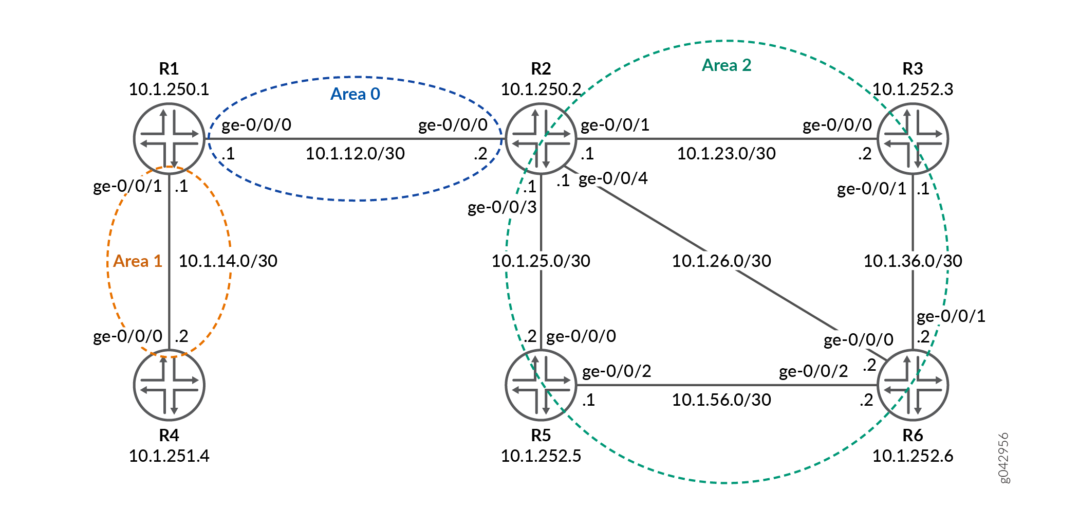
Topology
In the topology, Figure 1shows the longest match for LDP is configured on Device R0 .
Configuration
- CLI Quick Configuration
- Configuring Device R1
- Results
- Configuring Device R2
- Results
- Configuring Device R3
- Results
- Configuring Device R4
- Results
- Configuring Device R5
- Results
- Configuring Device R6
- Results
CLI Quick Configuration
To quickly configure this example, copy the
following commands, paste them into a text file, remove any line breaks,
change any details necessary to match your network configuration,
copy and paste the commands into the CLI at the [edit] hierarchy level, and then enter commit from configuration
mode.
R1
set system host-name R1-LDP
set interfaces ge-0/0/0 unit 0 family inet address 10.1.12.1/30
set interfaces ge-0/0/0 unit 0 family mpls
set interfaces ge-0/0/1 unit 0 family inet address 10.1.14.1/30
set interfaces ge-0/0/1 unit 0 family mpls
set interfaces lo0 unit 0 family inet address 10.1.250.1/32
set routing-options router-id 10.1.250.1
set protocols ldp longest-match
set protocols ldp interface ge-0/0/0.0
set protocols ldp interface ge-0/0/1.0
set protocols ldp interface lo0.0
set protocols mpls interface ge-0/0/0.0
set protocols mpls interface ge-0/0/1.0
set protocols ospf area 0.0.0.0 interface ge-0/0/0.0
set protocols ospf area 0.0.0.0 interface lo0.0 passive
set protocols ospf area 0.0.0.1 interface ge-0/0/1.0
R2
set system host-name R2-LDP
set interfaces ge-0/0/0 unit 0 family inet address 10.1.12.2/30
set interfaces ge-0/0/0 unit 0 family mpls
set interfaces ge-0/0/1 unit 0 family inet address 10.1.23.1/30
set interfaces ge-0/0/1 unit 0 family mpls
set interfaces ge-0/0/3 unit 0 family inet address 10.1.25.1/30
set interfaces ge-0/0/3 unit 0 family mpls
set interfaces ge-0/0/4 unit 0 family inet address 10.1.26.1/30
set interfaces ge-0/0/4 unit 0 family mpls
set interfaces lo0 unit 0 family inet address 10.1.250.2/32
set routing-options router-id 10.1.250.2
set protocols ldp interface ge-0/0/0.0
set protocols ldp interface ge-0/0/1.0
set protocols ldp interface ge-0/0/3.0
set protocols ldp interface ge-0/0/4.0
set protocols ldp interface lo0.0
set protocols mpls interface ge-0/0/1.0
set protocols mpls interface ge-0/0/3.0
set protocols mpls interface ge-0/0/0.0
set protocols mpls interface ge-0/0/4.0
set protocols ospf area 0.0.0.0 interface ge-0/0/0.0
set protocols ospf area 0.0.0.0 interface lo0.0 passive
set protocols ospf area 0.0.0.2 area-range 10.1.252.0/24
set protocols ospf area 0.0.0.2 interface ge-0/0/3.0
set protocols ospf area 0.0.0.2 interface ge-0/0/1.0
set protocols ospf area 0.0.0.2 interface ge-0/0/4.0
R3
set system host-name R3-LDP
set interfaces ge-0/0/0 unit 0 family inet address 10.1.23.2/30
set interfaces ge-0/0/0 unit 0 family mpls
set interfaces ge-0/0/1 unit 0 family inet address 10.1.36.1/30
set interfaces ge-0/0/1 unit 0 family mpls
set interfaces lo0 unit 0 family inet address 10.1.252.3/32
set routing-options router-id 10.1.252.3
set protocols ldp interface ge-0/0/0.0
set protocols ldp interface ge-0/0/1.0
set protocols ldp interface lo0.0
set protocols mpls interface ge-0/0/0.0
set protocols mpls interface ge-0/0/1.0
set protocols ospf area 0.0.0.2 interface ge-0/0/0.0
set protocols ospf area 0.0.0.2 interface lo0.0 passive
set protocols ospf area 0.0.0.2 interface ge-0/0/1.0
R4
set system host-name R4-LDP
set interfaces ge-0/0/0 unit 0 family inet address 10.1.14.2/30
set interfaces ge-0/0/0 unit 0 family mpls
set interfaces lo0 unit 0 family inet address 10.1.251.4/32
set routing-options router-id 10.1.251.4
set protocols ldp longest-match
set protocols ldp interface ge-0/0/0.0
set protocols ldp interface lo0.0
set protocols mpls interface ge-0/0/0.0
set protocols ospf area 0.0.0.1 interface ge-0/0/0.0
set protocols ospf area 0.0.0.1 interface lo0.0 passive
R5
set system host-name R5-LDP
set interfaces ge-0/0/0 unit 0 family inet address 10.1.25.2/30
set interfaces ge-0/0/0 unit 0 family mpls
set interfaces ge-0/0/2 unit 0 family inet address 10.1.56.1/30
set interfaces ge-0/0/2 unit 0 family mpls
set interfaces lo0 unit 0 family inet address 10.1.252.5/32
set routing-options router-id 10.1.252.5
set protocols ldp interface ge-0/0/0.0
set protocols ldp interface ge-0/0/2.0
set protocols ldp interface lo0.0
set protocols mpls interface ge-0/0/0.0
set protocols mpls interface ge-0/0/2.0
set protocols ospf area 0.0.0.2 interface ge-0/0/0.0
set protocols ospf area 0.0.0.2 interface lo0.0 passive
set protocols ospf area 0.0.0.2 interface ge-0/0/2.0
R6
set system host-name R6-LDP
set interfaces ge-0/0/0 unit 0 family inet address 10.1.26.2/30
set interfaces ge-0/0/0 unit 0 family mpls
set interfaces ge-0/0/1 unit 0 family inet address 10.1.36.2/30
set interfaces ge-0/0/1 unit 0 family mpls
set interfaces ge-0/0/2 unit 0 family inet address 10.1.56.2/30
set interfaces ge-0/0/2 unit 0 family mpls
set interfaces lo0 unit 0 family inet address 10.1.252.6/32
set routing-options router-id 10.1.252.6
set protocols ldp interface ge-0/0/0.0
set protocols ldp interface ge-0/0/1.0
set protocols ldp interface ge-0/0/2.0
set protocols ldp interface lo0.0
set protocols mpls interface ge-0/0/0.0
set protocols mpls interface ge-0/0/2.0
set protocols mpls interface ge-0/0/1.0
set protocols ospf area 0.0.0.2 interface ge-0/0/0.0
set protocols ospf area 0.0.0.2 interface lo0.0 passive
set protocols ospf area 0.0.0.2 interface ge-0/0/1.0
set protocols ospf area 0.0.0.2 interface ge-0/0/2.0
Configuring Device R1
Step-by-Step Procedure
The following example requires that you navigate various levels in the configuration hierarchy. For information about navigating the CLI, see Using the CLI Editor in Configuration Mode in the CLI User Guide.
To configure Device R1:
Set the system hostname.
[edit]
user@R1# set system host-name R1
-
Configure the interfaces.
[edit]
user@R1# set interfaces ge-0/0/0 unit 0 family inet address 10.1.12.1/30
user@R1# set interfaces ge-0/0/0 unit 0 family mpls
user@R1# set interfaces ge-0/0/1 unit 0 family inet address 10.1.14.1/30
user@R1# set interfaces ge-0/0/1 unit 0 family mpls
-
Assign the loopback addresses to the device.
[edit]
user@R1# set interfaces lo0 unit 0 family inet address 10.1.250.1/32
-
Configure the router ID.
[edit]
user@R1# set routing-options router-id 10.1.250.1
-
Configure the MPLS protocol on the interface.
[edit]
user@R1# set protocols mpls interface ge-0/0/0.0
user@R1# set protocols mpls interface ge-0/0/1.0
-
Configure the OSPF protocol on the interface.
[edit]
user@R1# set protocols ospf area 0.0.0.0 interface ge-0/0/0.0
user@R1# set protocols ospf area 0.0.0.0 interface lo0.0 passive
user@R1# set protocols ospf area 0.0.0.1 interface ge-0/0/1.0
-
Configure LDP protocol on the interface and longest match for the LDP protocol.
[edit]
user@R1# set protocols ldp interface ge-0/0/0.0
user@R1# set protocols ldp interface ge-0/0/1.0
user@R1# set protocols ldp interface lo0.0
user@R1# set protocols ldp longest-match
Results
From configuration mode, confirm your configuration by entering the show configuration | no-more command. If the output does not display the intended configuration, repeat the instructions in this example to correct the configuration.
user@R1#show configuration | no-more
system {
    host-name R1;
}
interfaces {
    ge-0/0/0 {
        unit 0 {
            family inet {
                address 10.1.12.1/30;
            }
            family mpls;
        }
    }
    ge-0/0/1 {
        unit 0 {
            family inet {
                address 10.1.14.1/30;
            }
            family mpls;
        }
    }
    lo0 {
        unit 0 {
            family inet {
                address 10.1.250.1/32;
            }
        }
    }
}
routing-options {
    router-id 10.1.250.1;
}
protocols {
    ldp {
        longest-match;
        interface ge-0/0/0.0;
        interface ge-0/0/1.0;
        interface lo0.0;
    }
    mpls {
        interface ge-0/0/0.0;
        interface ge-0/0/1.0;
    }
    ospf {
        area 0.0.0.0 {
            interface ge-0/0/0.0;
            interface lo0.0 {
                passive;
            }
        }
        area 0.0.0.1 {
            interface ge-0/0/1.0;
        }
    }
}
If you are done configuring the device, enter commit from the configuration mode.
Configuring Device R2
Step-by-Step Procedure
The following example requires that you navigate various levels in the configuration hierarchy. For information about navigating the CLI, see Using the CLI Editor in Configuration Mode in the CLI User Guide.
To configure Device R2:
Set the system hostname.
[edit]
user@R2# set system host-name R2
-
Configure the interfaces.
[edit]
user@R2# set interfaces ge-0/0/0 unit 0 family inet address 10.1.12.2/30
user@R2# set interfaces ge-0/0/0 unit 0 family mpls
user@R2# set interfaces ge-0/0/1 unit 0 family inet address 10.1.23.1/30
user@R2# set interfaces ge-0/0/1 unit 0 family mpls
user@R2# set interfaces ge-0/0/3 unit 0 family inet address 10.1.25.1/30
user@R2# set interfaces ge-0/0/3 unit 0 family mpls
user@R2# set interfaces ge-0/0/4 unit 0 family inet address 10.1.26.1/30
user@R2# set interfaces ge-0/0/4 unit 0 family mpls
-
Assign the loopback addresses to the device.
[edit]
user@R2# set interfaces lo0 unit 0 family inet address 10.1.250.2/32
-
Configure the router ID.
[edit]
user@R2# set routing-options router-id 10.1.250.2
-
Configure the MPLS protocol on the interface.
[edit]
user@R2# set protocols mpls interface ge-0/0/1.0
user@R2# set protocols mpls interface ge-0/0/3.0
user@R2# set protocols mpls interface ge-0/0/0.0
user@R2# set protocols mpls interface ge-0/0/4.0
-
Configure the OSPF protocol on the interface.
[edit]
user@R2# set protocols ospf area 0.0.0.0 interface ge-0/0/0.0
user@R2# set protocols ospf area 0.0.0.0 interface lo0.0 passive
user@R2# set protocols ospf area 0.0.0.2 area-range 10.1.252.0/24
user@R2# set protocols ospf area 0.0.0.2 interface ge-0/0/3.0
user@R2# set protocols ospf area 0.0.0.2 interface ge-0/0/1.0
user@R2# set protocols ospf area 0.0.0.2 interface ge-0/0/4.0
-
Configure LDP protocol on the interfaces.
[edit]
user@R2# set protocols ldp interface ge-0/0/0.0
user@R2# set protocols ldp interface ge-0/0/1.0
user@R2# set protocols ldp interface ge-0/0/3.0
user@R2# set protocols ldp interface ge-0/0/4.0
user@R2# set protocols ldp interface lo0.0
Results
From configuration mode, confirm your configuration by entering the show configuration | no-more command. If the output does not display the intended configuration, repeat the instructions in this example to correct the configuration.
user@R2#show configuration | no-more
system {
    host-name R2;
}
interfaces {
    ge-0/0/0 {
        unit 0 {
            family inet {
                address 10.1.12.2/30;
            }
            family mpls;
        }
    }
    ge-0/0/1 {
        unit 0 {
            family inet {
                address 10.1.23.1/30;
            }
            family mpls;
        }
    }
    ge-0/0/3 {
        unit 0 {
            family inet {
                address 10.1.25.1/30;
            }
            family mpls;
        }
    }
    ge-0/0/4 {
        unit 0 {
            family inet {
                address 10.1.26.1/30;
            }
            family mpls;
        }
    }
    lo0 {
        unit 0 {
            family inet {
                address 10.1.250.2/32;
            }
        }
    }
}
routing-options {
    router-id 10.1.250.2;
}
protocols {
    ldp {
        interface ge-0/0/0.0;
        interface ge-0/0/1.0;
        interface ge-0/0/3.0;
        interface ge-0/0/4.0;
        interface lo0.0;
    }
    mpls {
        interface ge-0/0/1.0;
        interface ge-0/0/3.0;
        interface ge-0/0/0.0;
        interface ge-0/0/4.0;
    }
    ospf {
        area 0.0.0.0 {
            interface ge-0/0/0.0;
            interface lo0.0 {
                passive;
            }
        }
        area 0.0.0.2 {
            area-range 10.1.252.0/24;
            interface ge-0/0/3.0;
            interface ge-0/0/1.0;
            interface ge-0/0/4.0;
        }
    }
}
If you are done configuring the device, enter commit from the
configuration mode.
Configuring Device R3
Step-by-Step Procedure
The following example requires that you navigate various levels in the configuration hierarchy. For information about navigating the CLI, see Using the CLI Editor in Configuration Mode in the CLI User Guide.
To configure Device R3:
Set the system hostname.
[edit]
user@R3# set system host-name R3
-
Configure the interfaces.
[edit]user@R3# set interfaces ge-0/0/0 unit 0 family inet address 10.1.23.2/30
user@R3# set interfaces ge-0/0/0 unit 0 family mpls
user@R3# set interfaces ge-0/0/1 unit 0 family inet address 10.1.36.1/30
user@R3# set interfaces ge-0/0/1 unit 0 family mpls
-
Assign the loopback addresses to the device.
[edit]
user@R3# set interfaces lo0 unit 0 family inet address 10.1.252.3/32
-
Configure the router ID.
[edit]
user@R3# set routing-options router-id 10.1.252.3
-
Configure the MPLS protocol on the interface.
[edit]
user@R3# set protocols mpls interface ge-0/0/0.0
user@R3# set protocols mpls interface ge-0/0/1.0
-
Configure the OSPF protocol on the interface.
[edit]
user@R3# set protocols ospf area 0.0.0.2 interface ge-0/0/0.0
user@R3# set protocols ospf area 0.0.0.2 interface lo0.0 passive
user@R3# set protocols ospf area 0.0.0.2 interface ge-0/0/1.0
-
Configure LDP protocol on the interface.
[edit]
user@R3# set protocols ldp interface ge-0/0/0.0
user@R3# set protocols ldp interface ge-0/0/1.0
user@R3# set protocols ldp interface lo0.0
Results
From configuration mode, confirm your configuration by entering the show configuration | no-more command. If the output does not display the intended configuration, repeat the instructions in this example to correct the configuration.
user@R3#show configuration | no-more
system {
    host-name R3;
}
interfaces {
    ge-0/0/0 {
        unit 0 {
            family inet {
                address 10.1.23.2/30;
            }
            family mpls;
        }
    }
    ge-0/0/1 {
        unit 0 {
            family inet {
                address 10.1.36.1/30;
            }
            family mpls;
        }
    }
    lo0 {
        unit 0 {
            family inet {
                address 10.1.252.3/32;
            }
        }
    }
}
routing-options {
    router-id 10.1.252.3;
}
protocols {
    ldp {
        interface ge-0/0/0.0;
        interface ge-0/0/1.0;
        interface lo0.0;
    }
    mpls {
        interface ge-0/0/0.0;
        interface ge-0/0/1.0;
    }
    ospf {
        area 0.0.0.2 {
            interface ge-0/0/0.0;
            interface lo0.0 {
                passive;
            }
            interface ge-0/0/1.0;
        }
    }
}
If you are done configuring the device, enter commit from the
configuration mode.
Configuring Device R4
Step-by-Step Procedure
The following example requires that you navigate various levels in the configuration hierarchy. For information about navigating the CLI, see Using the CLI Editor in Configuration Mode in the CLI User Guide.
To configure Device R4:
Set the system hostname.
[edit]
user@R4# set system host-name R4
-
Configure the interfaces.
[edit]
user@R4# set interfaces ge-0/0/0 unit 0 family inet address 10.1.14.2/30
user@R4# set interfaces ge-0/0/0 unit 0 family mpls
-
Assign the loopback addresses to the device.
[edit]
user@R4# set interfaces lo0 unit 0 family inet address 10.1.251.4/32
-
Configure the router ID.
[edit]
user@R4# set routing-options router-id 10.1.251.4
-
Configure the MPLS protocol on the interface.
[edit]
user@R4# set protocols mpls interface ge-0/0/0.0
-
Configure the OSPF protocol on the interface.
[edit]
user@R4# set protocols ospf area 0.0.0.1 interface ge-0/0/0.0
user@R4# set protocols ospf area 0.0.0.1 interface lo0.0 passive
-
Configure LDP protocol on the interface and longest match for the LDP protocol.
[edit]
user@R4# set protocols ldp interface ge-0/0/0.0
user@R4# set protocols ldp interface lo0.0
user@R4# set protocols ldp longest-match
Results
From configuration mode, confirm your configuration by entering the show configuration | no-more command. If the output does not display the intended configuration, repeat the instructions in this example to correct the configuration.
user@R4#show configuration | no-more
system {
    host-name R4;
}
interfaces {
    ge-0/0/0 {
        unit 0 {
            family inet {
                address 10.1.14.2/30;
            }
            family mpls;
        }
    }
    lo0 {
        unit 0 {
            family inet {
                address 10.1.251.4/32;
            }
        }
    }
}
routing-options {
    router-id 10.1.251.4;
}
protocols {
    ldp {
        longest-match;
        interface ge-0/0/0.0;
        interface lo0.0;
    }
    mpls {
        interface ge-0/0/0.0;
    }
    ospf {
        area 0.0.0.1 {
            interface ge-0/0/0.0;
            interface lo0.0 {
                passive;
            }
        }
    }
}
If you are done configuring the device, enter commit from the
configuration mode.
Configuring Device R5
Step-by-Step Procedure
The following example requires that you navigate various levels in the configuration hierarchy. For information about navigating the CLI, see Using the CLI Editor in Configuration Mode in the CLI User Guide.
To configure Device R5:
Set the system hostname.
[edit]
user@R5# set system host-name R5
-
Configure the interfaces.
[edit]
user@R5# set interfaces ge-0/0/0 unit 0 family inet address 10.1.25.2/30
user@R5# set interfaces ge-0/0/0 unit 0 family mpls
user@R5# set interfaces ge-0/0/2 unit 0 family inet address 10.1.56.1/30
user@R5# set interfaces ge-0/0/2 unit 0 family mpls
-
Assign the loopback addresses to the device.
[edit]
user@R5# set interfaces lo0 unit 0 family inet address 10.1.252.5/32
-
Configure the router ID.
[edit]
user@R5# set routing-options router-id 10.1.252.5
-
Configure the MPLS protocol on the interface.
[edit]
user@R5# set protocols mpls interface ge-0/0/0.0
user@R5# set protocols mpls interface ge-0/0/2.0
-
Configure the OSPF protocol on the interface.
[edit]
user@R5# set protocols ospf area 0.0.0.2 interface ge-0/0/0.0
user@R5# set protocols ospf area 0.0.0.2 interface lo0.0 passive
user@R5# set protocols ospf area 0.0.0.2 interface ge-0/0/2.0
-
Configure LDP protocol on the interface.
[edit]
user@R5# set protocols ldp interface ge-0/0/0.0
user@R5# set protocols ldp interface ge-0/0/2.0
user@R5# set protocols ldp interface lo0.0
Results
From configuration mode, confirm your configuration by entering the show configuration | no-more command. If the output does not display the intended configuration, repeat the instructions in this example to correct the configuration.
user@R5#show configuration | no-more
system {
    host-name R5;
}
interfaces {
    ge-0/0/0 {
        unit 0 {
            family inet {
                address 10.1.25.2/30;
            }
            family mpls;
        }
    }
    ge-0/0/2 {
        unit 0 {
            family inet {
                address 10.1.56.1/30;
            }
            family mpls;
        }
    }
    lo0 {
        unit 0 {
            family inet {
                address 10.1.252.5/32;
            }
        }
    }
}
routing-options {
    router-id 10.1.252.5;
}
protocols {
    ldp {
        interface ge-0/0/0.0;
        interface ge-0/0/2.0;
        interface lo0.0;
    }
    mpls {
        interface ge-0/0/0.0;
        interface ge-0/0/2.0;
    }
    ospf {
        area 0.0.0.2 {
            interface ge-0/0/0.0;
            interface lo0.0 {
                passive;
            }
            interface ge-0/0/2.0;
        }
    }
}
If you are done configuring the device, enter commit from the
configuration mode.
Configuring Device R6
Step-by-Step Procedure
The following example requires that you navigate various levels in the configuration hierarchy. For information about navigating the CLI, see Using the CLI Editor in Configuration Mode in the CLI User Guide.
To configure Device R6:
Set the system hostname.
[edit]
user@R6# set system host-name R6
-
Configure the interfaces.
[edit]
user@R6# set interfaces ge-0/0/0 unit 0 family inet address 10.1.26.2/30
user@R6# set interfaces ge-0/0/0 unit 0 family mpls
user@R6# set interfaces ge-0/0/1 unit 0 family inet address 10.1.36.2/30
user@R6# set interfaces ge-0/0/1 unit 0 family mpls
user@R6# set interfaces ge-0/0/2 unit 0 family inet address 10.1.56.2/30
user@R6# set interfaces ge-0/0/2 unit 0 family mpls
-
Assign the loopback addresses to the device.
[edit]
user@R6# set interfaces lo0 unit 0 family inet address 10.1.252.6/32
-
Configure the router ID.
[edit]
user@R6# set routing-options router-id 10.1.252.6
-
Configure the MPLS protocol on the interface.
[edit]
user@R6# set protocols mpls interface ge-0/0/0.0
user@R6# set protocols mpls interface ge-0/0/2.0
user@R6# set protocols mpls interface ge-0/0/1.0
-
Configure the OSPF protocol on the interface.
[edit]
user@R6# set protocols ospf area 0.0.0.2 interface ge-0/0/0.0
user@R6# set protocols ospf area 0.0.0.2 interface lo0.0 passive
user@R6# set protocols ospf area 0.0.0.2 interface ge-0/0/1.0
user@R6# set protocols ospf area 0.0.0.2 interface ge-0/0/2.0
-
Configure LDP protocol on the interface.
[edit]
user@R6# set protocols ldp interface ge-0/0/0.0
user@R6# set protocols ldp interface ge-0/0/1.0
user@R6# set protocols ldp interface ge-0/0/2.0
user@R6# set protocols ldp interface lo0.0
Results
From configuration mode, confirm your configuration by entering the show configuration | no-more command. If the output does not display the intended configuration, repeat the instructions in this example to correct the configuration.
user@R6#show configuration | no-more
system {
    host-name R6;
}
interfaces {
    ge-0/0/0 {
        unit 0 {
            family inet {
                address 10.1.26.2/30;
            }
            family mpls;
        }
    }
    ge-0/0/1 {
        unit 0 {
            family inet {
                address 10.1.36.2/30;
            }
            family mpls;
        }
    }
    ge-0/0/2 {
        unit 0 {
            family inet {
                address 10.1.56.2/30;
            }
            family mpls;
        }
    }
    lo0 {
        unit 0 {
            family inet {
                address 10.1.252.6/32;
            }
        }
    }
}
routing-options {
    router-id 10.1.252.6;
}
protocols {
    ldp {
        interface ge-0/0/0.0;
        interface ge-0/0/1.0;
        interface ge-0/0/2.0;
        interface lo0.0;
    }
    mpls {
        interface ge-0/0/0.0;
        interface ge-0/0/2.0;
        interface ge-0/0/1.0;
    }
    ospf {
        area 0.0.0.2 {
            interface ge-0/0/0.0;
            interface lo0.0 {
                passive;
            }
            interface ge-0/0/1.0;
            interface ge-0/0/2.0;
        }
    }
}
If you are done configuring the device, enter commit from the
configuration mode.
Verification
Confirm that the configuration is working properly.
- Verifying the Routes
- Verifying LDP Overview Information
- Verify the LDP Entries in the Internal Topology Table
- Verify Only FEC Information of LDP Route
- Verify FEC and Shadow Routes of LDP
Verifying the Routes
Purpose
Verify that the expected routes are learned.
Action
On Device R4, from operational mode, run the show route table
command to display the routes in the routing table.
user@R4> show route table inet.0 10.1/16
inet.0: 20 destinations, 20 routes (20 active, 0 holddown, 0 hidden)
+ = Active Route, - = Last Active, * = Both

10.1.12.0/30       *[OSPF/10] 01:20:42, metric 2
                    >  to 10.1.14.1 via ge-0/0/0.0
10.1.14.0/30       *[Direct/0] 2d 02:01:16
                    >  via ge-0/0/0.0
10.1.14.2/32       *[Local/0] 2d 02:01:16
                       Local via ge-0/0/0.0
10.1.23.0/30       *[OSPF/10] 01:20:42, metric 3
                    >  to 10.1.14.1 via ge-0/0/0.0
10.1.25.0/30       *[OSPF/10] 01:20:42, metric 3
                    >  to 10.1.14.1 via ge-0/0/0.0
10.1.26.0/30       *[OSPF/10] 01:20:42, metric 3
                    >  to 10.1.14.1 via ge-0/0/0.0
10.1.36.0/30       *[OSPF/10] 01:20:42, metric 4
                    >  to 10.1.14.1 via ge-0/0/0.0
10.1.56.0/30       *[OSPF/10] 01:20:42, metric 4
                    >  to 10.1.14.1 via ge-0/0/0.0
10.1.250.1/32      *[OSPF/10] 01:20:42, metric 1
                    >  to 10.1.14.1 via ge-0/0/0.0
10.1.250.2/32      *[OSPF/10] 01:20:42, metric 2
                    >  to 10.1.14.1 via ge-0/0/0.0
10.1.251.4/32      *[Direct/0] 01:20:42
                    >  via lo0.0
10.1.252.0/24      *[OSPF/10] 01:20:42, metric 3
> to 10.1.14.1 via ge-0/0/0.0user@R4> show route table inet.3
inet.3: 5 destinations, 5 routes (5 active, 0 holddown, 0 hidden)
+ = Active Route, - = Last Active, * = Both
10.1.250.1/32 *[LDP/9] 01:20:52, metric 1
> to 10.1.14.1 via ge-0/0/0.0
10.1.250.2/32 *[LDP/9] 01:20:52, metric 1
> to 10.1.14.1 via ge-0/0/0.0, Push 299936
10.1.252.3/32 *[LDP/9] 01:20:52, metric 1
> to 10.1.14.1 via ge-0/0/0.0, Push 299952
10.1.252.5/32 *[LDP/9] 01:19:11, metric 1
> to 10.1.14.1 via ge-0/0/0.0, Push 299984
10.1.252.6/32 *[LDP/9] 01:17:59, metric 1
> to 10.1.14.1 via ge-0/0/0.0, Push 300000
user@R4> show route table mpls.0
mpls.0: 10 destinations, 10 routes (10 active, 0 holddown, 0 hidden)
+ = Active Route, - = Last Active, * = Both

0                  *[MPLS/0] 2d 02:01:49, metric 1
                       Receive
1                  *[MPLS/0] 2d 02:01:49, metric 1
                       Receive
2                  *[MPLS/0] 2d 02:01:49, metric 1
                       Receive
13                 *[MPLS/0] 2d 02:01:49, metric 1
                       Receive
300016             *[LDP/9] 01:21:14, metric 1
                    >  to 10.1.14.1 via ge-0/0/0.0, Pop
300016(S=0)        *[LDP/9] 01:21:14, metric 1
                    >  to 10.1.14.1 via ge-0/0/0.0, Pop
300064             *[LDP/9] 01:21:14, metric 1
                    >  to 10.1.14.1 via ge-0/0/0.0, Swap 299936
300080             *[LDP/9] 01:21:14, metric 1
                    >  to 10.1.14.1 via ge-0/0/0.0, Swap 299952
300096             *[LDP/9] 01:19:33, metric 1
                    >  to 10.1.14.1 via ge-0/0/0.0, Swap 299984
300112             *[LDP/9] 01:18:21, metric 1
                    >  to 10.1.14.1 via ge-0/0/0.0, Swap 300000
Meaning
The output shows all the routes in the routing table of Device R4.
Verifying LDP Overview Information
Purpose
Display LDP overview information.
Action
On Device R4, from operational mode, run the show ldp overview
command to display the overview of the LDP.
user@R4> show ldp overview
Instance: master
  Reference count: 3
  Router ID: 10.1.251.4
  LDP inet: enabled
  Transport preference: IPv4
  Message id: 13
  Configuration sequence: 5
  Deaggregate: disabled
  Explicit null: disabled
  IPv6 tunneling: disabled
  Strict targeted hellos: disabled
  Loopback if added: yes
  Route preference: 9
  Unicast transit LSP chaining: disabled
  P2MP transit LSP chaining: disabled
  Transit LSP statistics based on route statistics: disabled
  LDP route acknowledgement: enabled
  BGP export: enabled
  No TTL propagate: disabled
  LDP mtu discovery: disabled
  LDP SR Mapping Client: disabled
  Longest Match: enabled
  Capabilities enabled: none
  Egress FEC capabilities enabled: entropy-label-capability
  Downstream unsolicited Sessions:
    Operational: 1
    Retention: liberal
    Control: ordered
  Auto targeted sessions:
    Auto targeted: disabled
    Dynamic tunnel session count: 0
  P2MP:
    Recursive route: disabled
    Recursive fec: disabled
    No rsvp tunneling: disabled
  Timers:
    Keepalive interval: 10, Keepalive timeout: 30
    Link hello interval: 5, Link hello hold time: 15
    Targeted hello interval: 15, Targeted hello hold time: 45
    Label withdraw delay: 60, Make before break timeout: 30
    Make before break switchover delay: 3
    Link protection timeout: 120
  Graceful restart:
    Restart: disabled, Helper: enabled, Restart in process: false
    Reconnect time: 60000, Max neighbor reconnect time: 120000
    Recovery time: 160000, Max neighbor recovery time: 240000
  Traffic Engineering:
    Bgp igp: disabled
    Both ribs: disabled
    Mpls forwarding: disabled
  IGP:
    Tracking igp metric: disabled
    Sync session up delay: 10
  Session protection:
    Session protection: disabled
    Session protection timeout: 0
  Interface addresses advertising:
    10.1.14.2
    10.1.251.4
  LDP Job:
    Read job time quantum: 1000, Write job time quantum: 1000
    Read job loop quantum: 100, Write job loop quantum: 100
    Backup inbound read job time quantum: 1000, Backup outbound read job time quantum: 1000
    Backup inbound read job loop quantum: 100, Backup outbound read job loop quantum: 100
  Label allocation:
    Current number of LDP labels allocated: 5
    Total number of LDP labels allocated: 22
    Total number of LDP labels freed: 17
    Total number of LDP label allocation failure: 0
    Current number of labels allocated by all protocols: 5
Meaning
The output displays the LDP overview information of Device R4.
Verify the LDP Entries in the Internal Topology Table
Purpose
Display the route entries in the Label Distribution Protocol (LDP) internal topology table.
Action
On Device R4, from operational mode, run the show ldp route
command to display the internal topology table of LDP.
user@R4> show ldp route

Destination                            Next-hop intf/lsp/table  Next-hop address
 10.0.0.0/8                            fxp0.0                   10.52.191.254
 10.1.12.0/30                          ge-0/0/0.0               10.1.14.1
 10.1.14.0/30                          ge-0/0/0.0
 10.1.14.2/32
 10.1.23.0/30                          ge-0/0/0.0               10.1.14.1
 10.1.25.0/30                          ge-0/0/0.0               10.1.14.1
 10.1.26.0/30                          ge-0/0/0.0               10.1.14.1
 10.1.36.0/30                          ge-0/0/0.0               10.1.14.1
 10.1.56.0/30                          ge-0/0/0.0               10.1.14.1
 10.1.250.1/32                         ge-0/0/0.0               10.1.14.1
 10.1.250.2/32                         ge-0/0/0.0               10.1.14.1
 10.1.251.4/32                         lo0.0
 10.1.252.0/24                         ge-0/0/0.0               10.1.14.1
 10.52.160.0/19                        fxp0.0
 10.52.172.37/32
 66.129.0.0/16                         fxp0.0                   10.52.191.254
 172.16.0.0/12                         fxp0.0                   10.52.191.254
 192.168.0.0/16                        fxp0.0                   10.52.191.254
 224.0.0.5/32
user@R4> show ldp route | match 10.1.14.1

Destination                            Next-hop intf/lsp/table  Next-hop address
 10.1.12.0/30                          ge-0/0/0.0               10.1.14.1
 10.1.23.0/30                          ge-0/0/0.0               10.1.14.1
 10.1.25.0/30                          ge-0/0/0.0               10.1.14.1
 10.1.26.0/30                          ge-0/0/0.0               10.1.14.1
 10.1.36.0/30                          ge-0/0/0.0               10.1.14.1
 10.1.56.0/30                          ge-0/0/0.0               10.1.14.1
 10.1.250.1/32                         ge-0/0/0.0               10.1.14.1
 10.1.250.2/32                         ge-0/0/0.0               10.1.14.1
 10.1.252.0/24                         ge-0/0/0.0               10.1.14.1
Meaning
The output displays the route entries in the Label Distribution Protocol (LDP) internal topology table of Device R4.
Verify Only FEC Information of LDP Route
Purpose
Display only the FEC information of LDP route.
Action
On Device R4, from operational mode, run the show ldp route fec-only
command to display the routes in the routing table.
user@R4> show ldp route fec-only
Destination                            Next-hop intf/lsp/table  Next-hop address
 10.1.250.1/32                         ge-0/0/0.0               10.1.14.1
 10.1.250.2/32                         ge-0/0/0.0               10.1.14.1
 10.1.251.4/32                         lo0.0
 10.1.252.3/32                         ge-0/0/0.0               10.1.14.1
 10.1.252.5/32                         ge-0/0/0.0               10.1.14.1
 10.1.252.6/32                         ge-0/0/0.0               10.1.14.1
Meaning
The output displays only the FEC routes of LDP protocol available for Device R4.
Verify FEC and Shadow Routes of LDP
Purpose
Display the FEC and the shadow routes in the routing table.
Action
On Device R4, from operational mode, run the show ldp route
fec-and-route command to display the FEC and shadow routes in the
routing table.
user@R4> show ldp route fec-and-route

Destination                            Next-hop intf/lsp/table  Next-hop address
 10.0.0.0/8                            fxp0.0                   10.52.191.254
 10.1.12.0/30                          ge-0/0/0.0               10.1.14.1
 10.1.14.0/30                          ge-0/0/0.0
 10.1.14.2/32
 10.1.23.0/30                          ge-0/0/0.0               10.1.14.1
 10.1.25.0/30                          ge-0/0/0.0               10.1.14.1
 10.1.26.0/30                          ge-0/0/0.0               10.1.14.1
 10.1.36.0/30                          ge-0/0/0.0               10.1.14.1
 10.1.56.0/30                          ge-0/0/0.0               10.1.14.1
 10.1.250.1/32                         ge-0/0/0.0               10.1.14.1
 10.1.250.1/32                         ge-0/0/0.0               10.1.14.1
 10.1.250.2/32                         ge-0/0/0.0               10.1.14.1
 10.1.250.2/32                         ge-0/0/0.0               10.1.14.1
 10.1.251.4/32                         lo0.0
 10.1.251.4/32                         lo0.0
 10.1.252.0/24                         ge-0/0/0.0               10.1.14.1
 10.1.252.3/32                         ge-0/0/0.0               10.1.14.1
 10.1.252.5/32                         ge-0/0/0.0               10.1.14.1
 10.1.252.6/32                         ge-0/0/0.0               10.1.14.1
 10.52.160.0/19                        fxp0.0
 10.52.172.37/32
 66.129.0.0/16                         fxp0.0                   10.52.191.254
 172.16.0.0/12                         fxp0.0                   10.52.191.254
 192.168.0.0/16                        fxp0.0                   10.52.191.254
 224.0.0.5/32
user@R4> show ldp route fec-and-route | match 10.1.14.1

Destination                            Next-hop intf/lsp/table  Next-hop address
 10.1.12.0/30                          ge-0/0/0.0               10.1.14.1
 10.1.23.0/30                          ge-0/0/0.0               10.1.14.1
 10.1.25.0/30                          ge-0/0/0.0               10.1.14.1
 10.1.26.0/30                          ge-0/0/0.0               10.1.14.1
 10.1.36.0/30                          ge-0/0/0.0               10.1.14.1
 10.1.56.0/30                          ge-0/0/0.0               10.1.14.1
 10.1.250.1/32                         ge-0/0/0.0               10.1.14.1
 10.1.250.1/32                         ge-0/0/0.0               10.1.14.1
 10.1.250.2/32                         ge-0/0/0.0               10.1.14.1
 10.1.250.2/32                         ge-0/0/0.0               10.1.14.1
 10.1.252.0/24                         ge-0/0/0.0               10.1.14.1
 10.1.252.3/32                         ge-0/0/0.0               10.1.14.1
 10.1.252.5/32                         ge-0/0/0.0               10.1.14.1
 10.1.252.6/32                         ge-0/0/0.0               10.1.14.1
Meaning
The output displays the FEC and the shadow routes of Device R4.