Understanding Multipoint LDP Recursive FEC
The Multipoint LDP (MLDP) Recursive Forwarding Equivalence Class (FEC) is useful in a deployment in which the intermediate routers do not have the route to reach the root node.
We've introduced the recursive opaque value as defined in RFC 6512 that helps to form MLDP point-to-multipoint (P2MP) tunnels between two autonomous systems (ASs) when the backbone has no direct route to the root node. This enhances flexibility and robustness of MLDP in complex network configurations, especially when spanning multiple autonomous systems.
To overcome the issue of establishing MLDP P2MP tunnels when the backbone has no direct route to the root node, RFC 6512 provides a solution to temporarily replace the actual root node address with the address known to the intermediate nodes, making it possible to establish the path through the network even in inter-AS scenarios involving BGP and Multipoint-to-Multipoint Label Switched Paths (MP LSPs). For a P2MP LSP, the root node address and its associated opaque value are the key components used to route MLDP messages through the MLDP control plane and create the P2MP LSP.
.
How it works
To form an MLDP tunnel, an application provides the root address and opaque value to LDP. It also informs LDP to be the egress for the particular P2MP LSP. The label advertised for P2MP FEC by the egress Label-switching router (LSR) can be decided either by LDP or the application. The LSR then finds the upstream router to the root by performing a route lookup. The labels assigned for the FEC are advertised as a label mapping message to the upstream router.
A transit LSR upon receiving a label advertisement from the downstream LSR advertises a label to the upstream LSR towards the root in the P2MP FEC. It also installs the necessary forwarding state to forward the packets when they arrive with the label it advertised. This repeats on each router till the label reaches the ingress router.
At the ingress LSR, mapping the traffic onto the P2MP LSP is determined by the application. Thus, LDP does not install any forwarding state for the P2MP LSP. However, it provides necessary information about the P2MP LSP to the application so that the application installs the forwarding state.
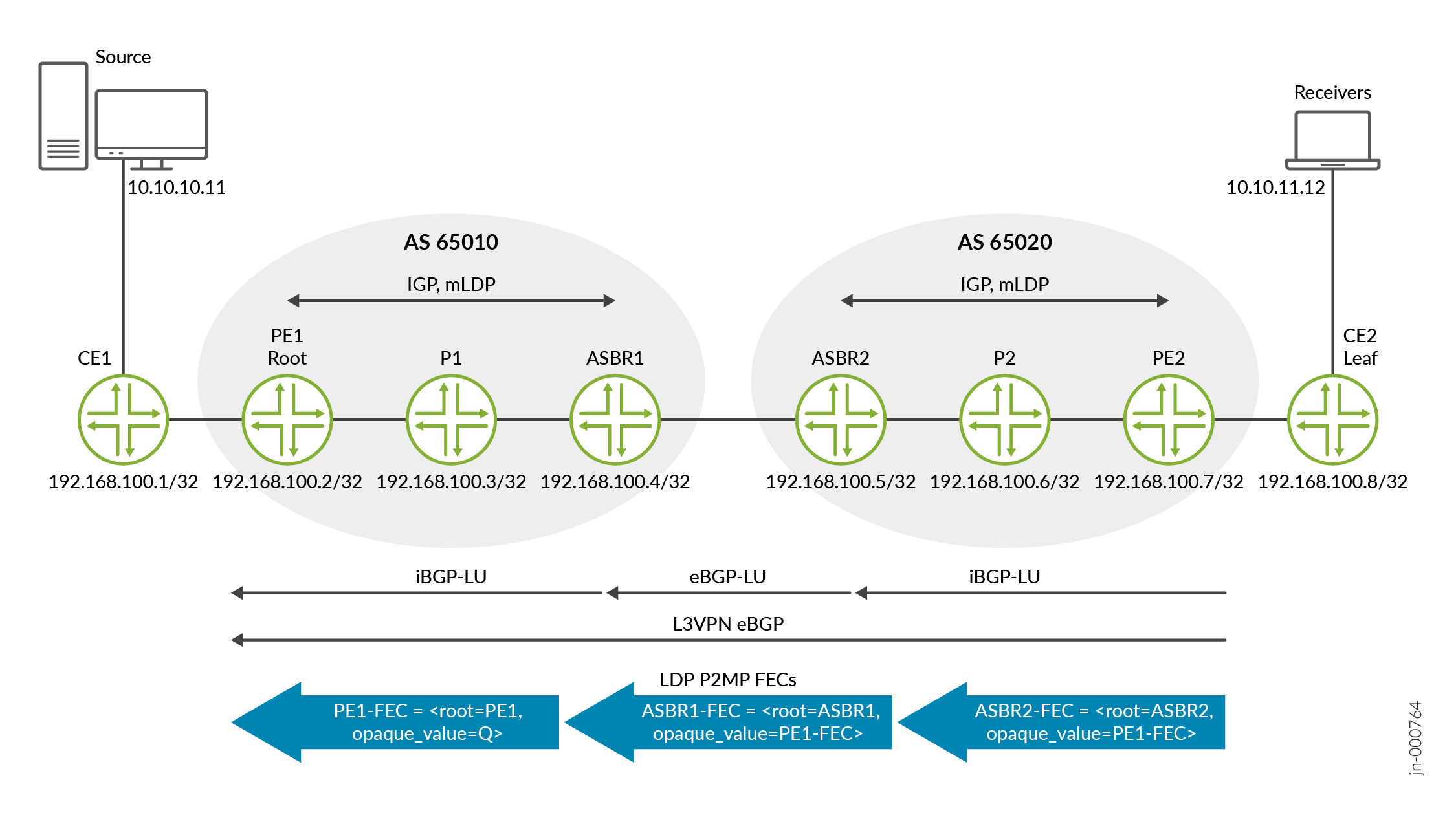
Figure 1 depicts a host system capable of sending multicast traffic and a host system capable of receiving multicast traffic.
The Provider edge (PE) and AS border router (ASBR) routers have route to the root PE1. The P (P1 and P2) routers do not have a route towards the root. The MLDP P2MP tunnel is formed from the egress to the ingress routers. When the egress router PE2 tries to send a label map message to the root PE1, it finds that the upstream router to reach the root PE1 is P2. Therefore, label map message is sent to P2. However, P2 does not have a route to the root and the upstream router for the root cannot be found. Therefore, P2 cannot send a label map message to its upstream router and hence tunnel cannot be formed.
In such topologies, recursive opaque value feature is enabled using the set
protocol ldp p2mp recursive fec configuration statement.
The recursive P2MP comes into effect if the route to the root is an indirect BGP route.
Let's understand this in detail:
-
For LDP to form a P2MP tunnel from leaf PE2 to root PE1, PE2 creates an MP FEC element with the address of PE1 as the root node address as follows: PE1-FEC = <root=PE1, opaque_value=Q>
-
PE2 sends the FEC element as MLDP label map message to P2. However, P2 cannot use the FEC element because it does not have a route to PE1.
-
With
set
          protocol ldp p2mp recursive fec
configuration statement configured, PE2 determines that the root node's address matches a BGP route, with ASBR2 as the protocol next-hop. -
Therefore, PE2 creates the new MP FEC element with the recursive opaque value. Within the FEC element, the root node address is the address of the protocol nexthop ASBR2 and the opaque value is a recursive opaque value that contains PE2-FEC. We refer to this FEC element as ASBR2-FEC. ASBR2-FEC = <root=ASBR2, opaque_value=PE1-FEC> which is PE1-FEC = <root=PE1, opaque_value=<root=S, opaque_value=Q>>
-
LDP requests the interior routers (P1 and P2) to build an MP LSP for which the root node is ASBR2. However, the routers must not interpret the opaque value.
-
When ASBR2-FEC arrives at ASBR2, ASBR2 notes that it is the identified root node and that the opaque value is a recursive opaque value. Therefore, ASBR2 reads the opaque value to find the actual root.
-
Then ASBR2 does a lookup to find the route to actual root, that is PE1. As the route to PE1 is a BGP route with an indirect next hop, ASBR2 determines that it should form a LDP recursive FEC to the root PE1 with the protocol nexthop as ASBR1 and keep the received opaque value intact. ASBR1-FEC = <root=ASBR1, opaque_value=PE1-FEC>
-
When ASBR1-FEC arrives at ASBR1, ASBR1 notes that it is the identified root node and that the opaque value is a recursive opaque value. Therefore, ASBR1 reads the opaque value to find the actual root. The ASBR1 finds the route to the root which is an IGP route. So ASBR1 replaces ASBR1-FEC with the contents of the recursive opaque value, that is, with PE1-FEC before any further processing.
-
This results in PE1-FEC being sent on to P1. PE1-FEC = <root=PE1, opaque_value=<root=S, opaque_value=Q>> P1.
-
PE1 receives the PE1-FEC and processes it like any normal LDP P2MP FEC.
The recursive P2MP FEC is not applicable for PIM in-band signalling and static LDP P2MP tunnel.