Storage Media and Routing Engines (Junos OS)
The Routing Engine and the Packet Forwarding Engine (PFE) are the two primary components of Juniper Networks platforms. Junos OS software is installed on the routing engine and it is stored in storage media.
Routing Engines and Storage Media (Junos OS)
Juniper Networks routing platforms are made up of two basic routing components:
Routing Engine—The Routing Engine controls the routing updates and system management.
Packet Forwarding Engine (PFE)—The Packet Forwarding Engine performs Layer 2 and Layer 3 packet switching, route lookups, and packet forwarding.
From a system administration perspective, you install the software onto the Routing Engine and during the installation, the appropriate software is forwarded to other components as necessary. Most Routing Engines include a CompactFlash card that stores Junos OS. On M Series Multiservice Edge Routers; MX240, MX480, and MX960 Universal Routing Platforms; T Series Core Routers; and TX Matrix routers, the system also includes a hard disk or solid-state drive (SSD) that acts as a backup boot drive. PTX Series Packet Transport Routers and the TX Matrix Plus router include a solid-state drive as a backup boot drive.
The MX80 router is a single-board router with a built-in Routing Engine and single Packet Forwarding Engine. On an MX80 router, Junos OS is stored on dual, internal NAND flash devices. These devices provide the same functionality as a CompactFlash card and hard disk or solid-state drive (SSD).
The ACX Series router is a single board router with a built-in Routing Engine and one Packet Forwarding Engine. The ACX router supports dual-root partitioning, which means that the primary and backup Junos OS images are kept in two independently bootable root partitions. If the primary partition becomes corrupted, the system remains fully functional by booting from the backup Junos OS image located in the other root partition.
On routing platforms with dual Routing Engines, each Routing Engine is independent with regard to upgrading the software. To install new software on both Routing Engines, you need to install the new software on each Routing Engine. On platforms with dual Routing Engines configured for high availability, you can use the unified in-service software upgrade procedure to upgrade the software. For more information about this procedure, see the High Availability User Guide for Routing Devices.
Repartitioning Routing Engine System Storage to Increase the Swap Partition (Junos OS)
You can increase the size of the swap partition by repartitioning the drive (hard disk or solid-state drive [SSD]) on the Routing Engine. This feature is first available in Junos OS Release 10.4R5, 11.1R3, and 11.2R1; in earlier Junos OS releases, the swap partition is not increased by the methods described here.
This behavior applies only to Routing Engines with more than 2 GB of RAM. The new size of the swap partition depends on the size of the drive and the amount of Routing Engine RAM.
When the drive is 32 GB or less, the swap partition is limited to 8 GB.
When the drive is larger than 32 GB, the swap partition matches the size of the Routing Engine RAM.
To repartition the drive, perform one of the following actions:
During the installation of a Junos OS software package (jinstall*), issue the
request
system reboot media disk
command to boot from the drive instead of issuing therequest system rebootcommand. The drive is automatically repartitioned. Therequest system reboot media diskcommand repartitions the drive only during a software upgrade.Manually partition the drive by issuing the
request
system partition hard-disk
command, and then reboot the router when the command completes.
Repartitioning the drive re-creates the /config and /var directories in the router file system. Although the contents of /config and /var/db are preserved, the remaining contents of /var are lost. For this reason, we recommend that you back up the /var directory before you repartition the SSD on a router with this configuration.
System Memory and Storage Media on Routers (Junos OS)
Figure 1 shows examples of Routing Engines.
System Memory
Starting with Junos OS Release 9.0, all routing platforms require
a minimum of 512 MB of system memory on each Routing Engine.
All M7i and M10i routers delivered before December 7, 2007, had 256
MB of memory. These routers require a system memory upgrade before
you install Junos OS Release 9.0 or a later release. To determine
the amount of memory currently installed on your system, use the show chassis routing-engine command in the command-line interface
(CLI).
For more information about upgrading your M7i or M10i router, see the Customer Support Center JTAC Technical Bulletin PSN-2007-10-001: https://www.juniper.net/alerts/viewalert.jsp?txtAlertNumber=PSN-2007-10-001&actionBtn=Search.
ACX2000 routers are shipped with 2 GB of memory and ACX1000 routers with 1 GB of memory.
Storage Media
Except for the ACX Series, MX80 routers, and MX104 routers, the M Series, MX Series, PTX Series, T Series, TX Matrix, and TX Matrix Plus routers use the following media storage devices:
-
CompactFlash card—The CompactFlash card is typically the primary storage device for most routers.
Note:M7i and M10i routers using RE-400 are not delivered from the factory with the CompactFlash card installed. In this case, the hard disk is the primary and only boot device. The M7i and M10i routers with RE-400 can be upgraded to include the CompactFlash card.
-
Hard disk or solid -state drive—For most routers, a hard disk or solid-state drive is the secondary boot device. When the CompactFlash card is not installed on the router, the hard disk or the solid-state drive becomes the primary boot device. The hard disk or solid-state drive is also used to store system log files and diagnostic dump files.
-
Emergency boot device—Depending on the router, the emergency boot device can be a PC card, a USB storage device, or an LS-120 floppy disk.
On MX80 routers, the internal NAND flash devices (first da0, then da1) act as the primary and secondary boot devices.
On ACX Series routers, the internal NAND flash devices (first da0s1, then da0s2) act as the primary and secondary boot devices.
Emergency boot devices can be used to revive a routing platform that has a damaged Junos OS. When an emergency boot device is attached to the router, the router attempts to boot from that device before it boots from the CompactFlash card, solid-state drive (SSD), or hard disk.
On an ACX Series router, the emergency boot device is a USB storage device.
On MX104 routers, the internal NAND flash device (da0) mounted on the internal eUSB card acts as the primary boot and storage device. On MX104 routers, the emergency boot device is a USB storage device that is plugged into one of the USB ports in the front plate.
When booting from an emergency boot device, the router requests a boot acknowledgment on the console interface. If you enter yes, the emergency boot device repartitions the primary boot device and reloads Junos OS onto the primary boot device. After the loading is complete, the routing platform requests that you remove the emergency boot device and reboot the system. After the reboot is complete, you must perform an initial configuration of the router before it can be used on your network.
For routers with RE-MX-X6, RE-MX-X8, and RE-PTX-X8 Routing Engines, a set of two 64-GB SSDs are available for storage and redundancy. For more information see Storage Partitioning and Redundancy topic in Salient Features of the Routing Engines with VM Host Support section.
Routing Engines and Storage Media Names (ACX Series, M Series, MX Series, PTX Series, T Series, TX Matrix, TX Matrix Plus, and JCS 1200 Routers)
Table 1 specifies the storage media names by Routing Engine. The storage media device names are displayed when the router boots.
Routing Engine |
Type of Junos OS |
CompactFlash Card |
Hard Disk |
Solid-State Drive |
Removable Media Emergency Boot Device |
|---|---|---|---|---|---|
RE-400-768 (RE5) |
FreeBSD 6.x |
ad0 |
ad1 |
No |
ad3 |
RE-600-2048 (RE3) |
FreeBSD 6.x |
ad0 |
ad1 |
No |
ad3 |
RE-850-1536 (RE-850) |
FreeBSD 6.x |
ad0 |
ad1 |
No |
ad3 |
RE-A-1000-2048 (RE-A-1000) |
FreeBSD 6.x |
ad0 |
ad2 |
No |
da0 |
RE-A-1800x2 (RE-A-1800) |
FreeBSD 6.x |
ad0 |
No |
Yes SSD1: ad1 SSD2: ad2 |
da0 |
RE-S-1300-2048 (RE-S-1300) |
FreeBSD 6.x |
ad0 |
ad2 |
No |
da0 |
RE-S-1800x2RE-S-1800x4(RE-S-1800) |
FreeBSD 6.x |
ad0 |
No |
Yes SSD1: ad1 SSD2: ad2 |
da0 |
FreeBSD 10.x/11.x |
|||||
RE-B-1800X1-4G-S |
FreeBSD 6.x |
ad0 |
No |
Yes SSD1: ad1 |
da0 |
RE-1600-2048 (RE4) |
FreeBSD 6.x |
ad0 |
ad1 |
No |
ad3 and ad4 |
RE-A-2000-4096 (RE-A-2000) |
FreeBSD 6.x |
ad0 |
ad2 |
No |
da0 |
RE-S-2000-4096 (RE-S-2000) |
FreeBSD 6.x |
ad0 |
ad2 |
No |
da0 |
RE-MX-104 |
FreeBSD 6.x |
No |
da0 |
No |
da1 and da2 |
RE-DUO-C2600-16G (RE-DUO-2600) |
FreeBSD 6.x |
ad0 |
No |
ad1 |
da0 |
RE-DUO-C1800-8G- (RE-DUO-1800) |
FreeBSD 6.x |
ad0 |
No |
ad1 |
da0 |
RE-DUO-C1800-16G |
FreeBSD 6.x |
ad0 |
No |
ad1 |
da0 |
RE-JCS1200-1x2330 |
FreeBSD 6.x |
da0 |
da1 |
No |
da2 |
RE-PTX-X8-64G |
FreeBSD 6.x |
No |
No |
Yes SSD1: sda SSD2: sdb |
da0 |
RE-S-X6-64G |
FreeBSD 6.x |
No |
No |
Yes SSD1: sda SSD2: sdb |
da0 |
REMX2K-X8-64G |
FreeBSD 6.x |
No |
No |
Yes SSD1: sda SSD2: sdb |
da0 |
On MX80 routers, the Routing Engine is a built-in device and has no model number. The dual internal NAND flash devices are da0 and da1. The USB storage device is da2.
On ACX Series routers, the Routing Engine is a built-in
device which does not have a model number. The dual internal NAND
flash devices are da0s1 and da0s2. The USB storage device is da0s2a.
Use the show chassis hardware models command to obtain
the field-replaceable unit (FRU) model number—for example, ACX2000BASE-DC for the ACX2000 router.
To view the storage media currently available on your
system, use the CLI show system storage command.
See Also
System Memory and Storage Media for SRX Series Firewalls
SRX Series Firewalls Overview
Figure 2 shows the front panel of an SRX345 Firewall.
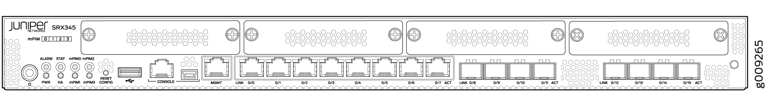
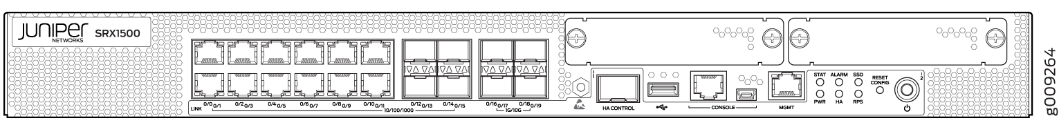
Figure 3 shows an example of an SRX1500 Firewall.
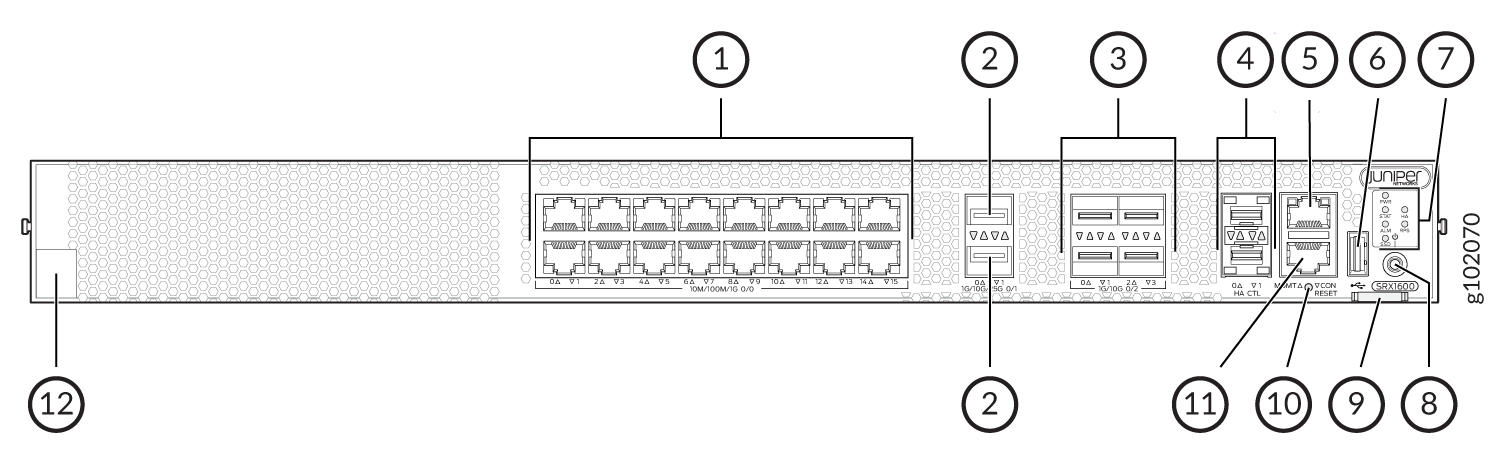
The below table lists and describes the front panel components of the firewall.
|
Callout |
Component (Label on the Chassis) |
Description |
|---|---|---|
| 1 |
Ethernet ports |
Sixteen 10/100/1000 BASE-T ports (PIC 0 ports) |
| 2 |
SFP28 ports |
Two 1/10/25 GbE SFP28 MACsec ports for network traffic (PIC 1 ports) |
| 3 |
SFP+ ports |
Four 1/10 GbE SFP+ MACsec ports for network traffic (PIC 2 ports) |
| 4 |
Chassis cluster ports (HA) |
Two 1 GbE SFP chassis cluster control CTL ports with MACsec support |
| 5 |
Management port (MGMT) |
1 GbE RJ-45 port |
| 6 |
USB port |
One USB 3.0 Type A port that accepts a USB storage device |
| 7 | Chassis LEDs |
Indicate component and system status and troubleshooting information at a glance. |
| 8 |
Power button |
Power button |
| 9 | Pull tab | Contains the CLEI code and serial number of the device |
| 10 |
RESET |
Reset button. To reset the system, press and hold the RESET button for around 250 ms. |
| 11 |
Console port (CON) |
You can connect a laptop to the SRX1600 to manage the CLI. The port uses an RJ-45 serial connection and supports the RS-232 (EIA-232) standard. |
| 12 |
Claim code |
You can use the QR code to claim and onboard your device to Juniper Security Director. |
The BASE-T PIC 0 ports (ge-0/0/0 to ge-0/0/15) support autonegotiation. The SFP28 PIC 1 ports (et-0/1/0 to et-0/1/1) do not support SFP-T or autonegotiation. The SFP+ PIC 2 ports (xe-0/2/0 to xe-0/2/3) support 1 GbE SFP-T but do not support autonegotiation.
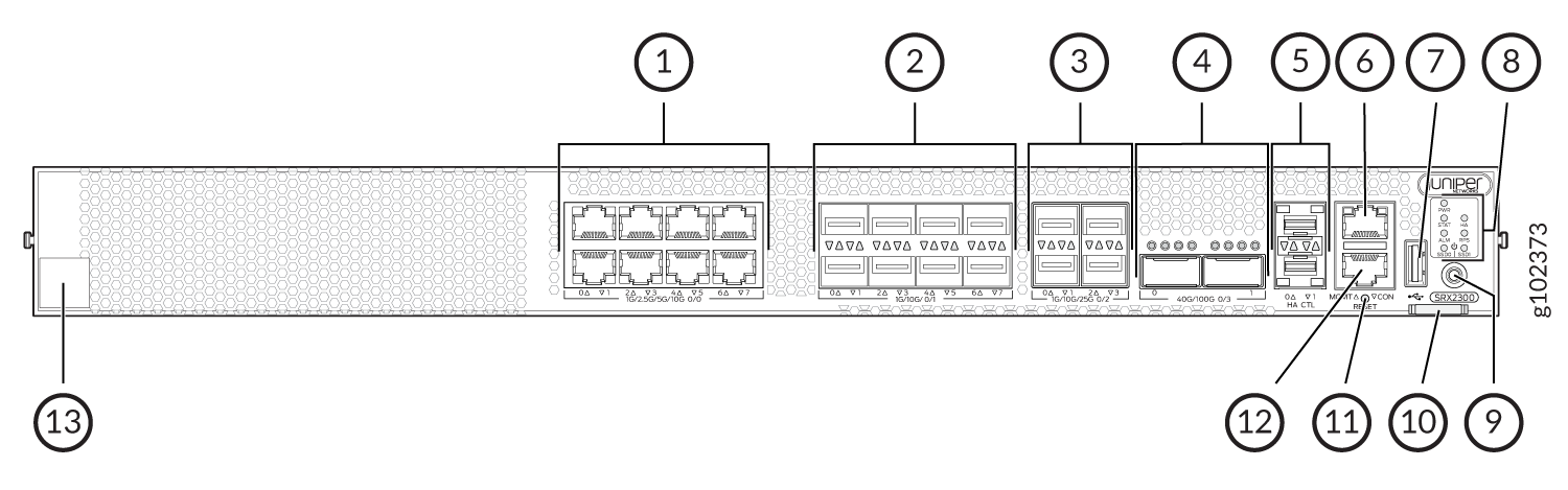
The below table lists and describes the front panel components of the firewall.
|
Callout |
Component (Label on the Chassis) |
Description |
|---|---|---|
| 1 |
Ethernet ports |
Eight 1/2.5/5/10-Gigabit Ethernet MACsec ports for network traffic (PIC 0 ports) |
| 2 |
SFP+ ports |
Eight 1/10-Gigabit Ethernet SFP+ MACsec ports for network traffic (PIC 1 ports) |
| 3 |
SFP28 ports |
Four 1/10/25-Gigabit Ethernet SFP28 MACsec ports for network traffic (PIC 2 ports) |
| 4 |
QSFP28 |
Two 40/100-Gigabit Ethernet QSFP28 MACsec ports for network traffic (PIC 3 ports) |
| 5 |
Chassis cluster ports (HA) |
Two 1-Gigabit Ethernet SFP chassis cluster control CTL ports with MACsec support |
| 6 |
Management port (MGMT) |
1-Gigabit Ethernet RJ-45 port |
| 7 |
USB port |
One USB 3.0 Type A port that accepts a USB storage device. |
| 8 | Chassis LEDs |
Indicate component and system status and troubleshooting information at a glance. |
| 9 |
Power button |
Power button |
| 10 | Pull tab | Contains the CLEI code and serial number of the device. |
| 11 |
RESET |
Reset button. To reset the system, press and hold the RESET button for around 250 ms. |
| 12 |
Console port (CON) |
You can connect a laptop to the SRX2300, SRX4120 for CLI management. The port uses an RJ-45 serial connection and supports the RS-232 (EIA-232) standard. |
| 13 |
Claim code |
You can use the QR code to claim and onboard your device to Juniper Security Director. |
The BASE-T PIC 0 ports (mge-0/0/0 to mge-0/0/7) support autonegotiation. The SFP+ PIC 1 ports (xe-0/1/0 to xe-0/1/7) support 1 GbE SFP-T but do not support autonegotiation. The SFP28 PIC 2 ports (et-0/2/0 to et-0/2/3) and QSFP28 PIC 3 ports (et-0/3/0 to et-0/3/1) do not support SFP-T or autonegotiation.
Figure 6 shows an example of an SRX4200 Firewall.
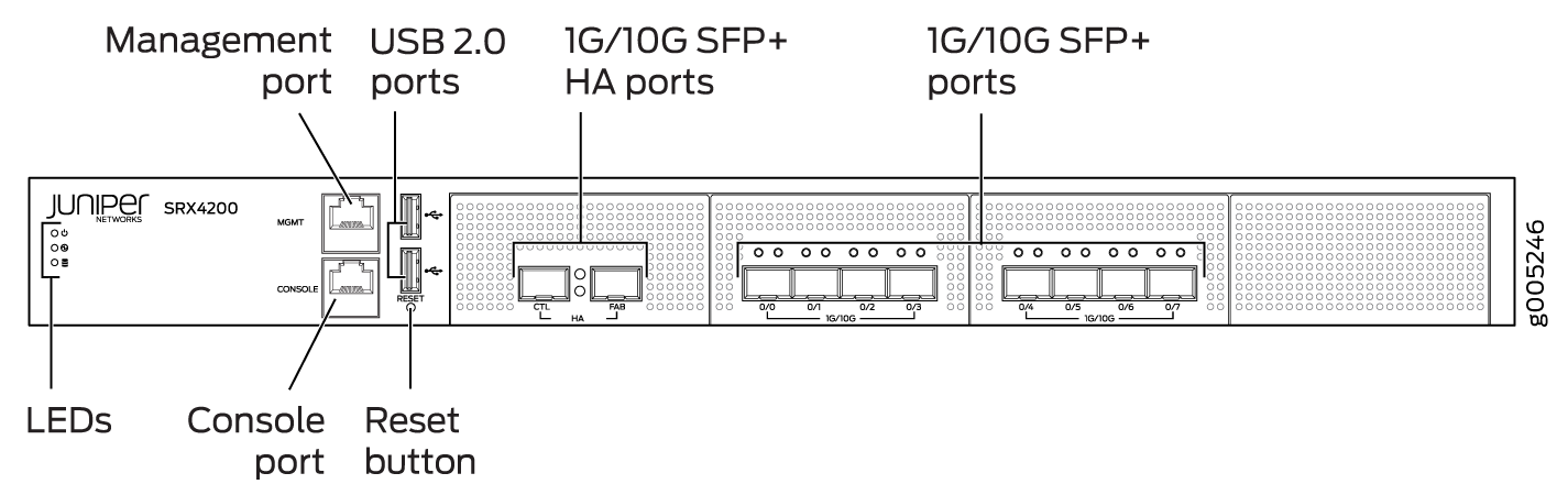
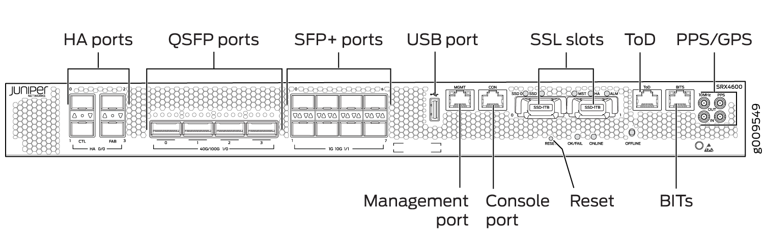
Figure 8 shows an example of an SRX4600 Firewall.
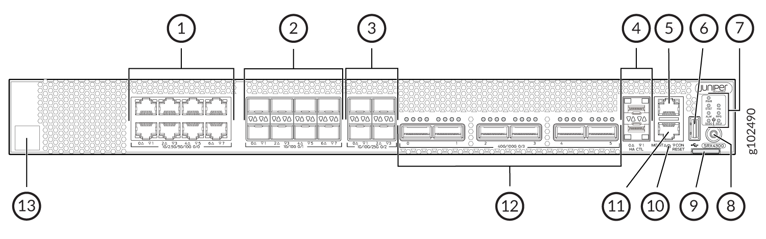
The below table lists and describes the front panel components of the firewall.
|
Callout |
Component (Label on the Chassis) |
Description |
|---|---|---|
| 1 |
Ethernet ports |
Eight 1/2.5/5/10-Gigabit Ethernet MACsec ports for network traffic. |
| 2 |
SFP+ ports |
Eight 1/10-Gigabit Ethernet SFP+ MACsec ports for network traffic. |
| 3 |
SFP28 ports |
Four 1/10/25-Gigabit Ethernet SFP28 MACsec ports for network traffic. |
| 4 |
Chassis cluster ports (HA) |
Two 1-Gigabit Ethernet SFP chassis cluster control CTL ports with MACsec support |
| 5 |
Management port (MGMT) |
1-Gigabit Ethernet RJ-45 port |
| 6 |
USB port |
One USB 3.0 Type A port that accepts a USB storage device. |
| 7 | Chassis LEDs |
Indicate component and system status and troubleshooting information at a glance. |
| 8 |
Power button |
Power button |
| 9 | Pull tab | Contains the CLEI code and serial number of the device. |
| 10 |
RESET |
Reset button. To reset the system, press and hold the RESET button for around 250 ms. |
| 11 |
Console port (CON) |
You can connect a laptop to the SRX4300 for CLI management. The port uses an RJ-45 serial connection and supports the RS-232 (EIA-232) standard. |
| 12 |
QSFP28 ports |
Six 4x10/4x25/2x50/40/100-Gigabit Ethernet QSFP28 MACsec ports for network traffic. |
| 13 |
Claim code |
You can use the QR code to claim and onboard your device to Juniper Security Director. |
The BASE-T PIC 0 ports (mge-0/0/0 to mge-0/0/7) support autonegotiation. The SFP+ PIC 1 ports (xe-0/1/0 to xe-0/1/7) support 1 GbE SFP-T but do not support autonegotiation. The SFP28 PIC 2 ports (et-0/2/0 to et-0/2/3) and QSFP28 PIC 3 ports (et-0/3/0 to et-0/3/5) do not support SFP-T or autonegotiation.
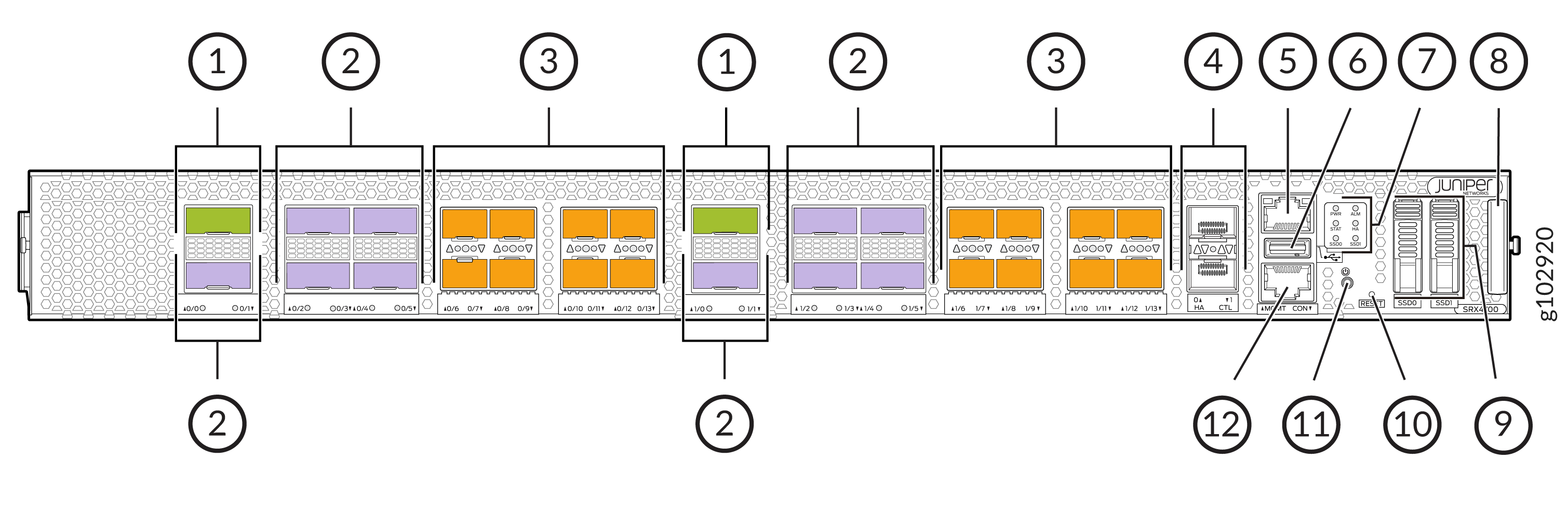
The below table lists and describes the front panel components of the firewall.
|
Callout |
Component (Label on the Chassis) |
Description |
|---|---|---|
|
1 |
QSFP56-DD ports |
Two 400-Gigabit Ethernet QSFP56-DD MACsec ports for network traffic. |
|
2 |
QSFP28 ports |
Ten 100-Gigabit Ethernet QSFP28 MACsec ports for network traffic. |
|
3 |
SFP56 ports |
Sixteen 50-Gigabit Ethernet SFP56 MACsec ports for network traffic. |
|
4 |
Chassis cluster ports (HA) |
Two 1-Gigabit Ethernet SFP chassis cluster control CTL ports with MACsec support |
|
5 |
Management port (MGMT) |
1-Gigabit Ethernet RJ-45 port |
|
6 |
USB port |
One USB 3.0 Type A port that accepts a USB storage device. |
|
7 |
Chassis LEDs |
Indicate component and system status and troubleshooting information at a glance. |
|
8 |
Pull-out Information Tab |
Contains the serial number. |
|
9 |
SSD |
2x1TB M.2 SSD or 1x1TB M.2 SSD + 1x2TB M.2 SSD |
|
10 |
RESET |
Reset button. To reset the system, press and hold the RESET button for around 250 ms. |
|
11 |
Power button |
Power button |
|
12 |
Console port (CON) |
You can connect a laptop to the SRX4700 for CLI management. The port uses an RJ-45 serial connection and supports the RS-232 (EIA-232) standard. |
Figure 10 shows an example of an SRX5800 Firewall Routing Engine.
System Memory
The amount of free disk space necessary to upgrade a device with a new version of Junos OS can vary from one release to another for different SRX Series Firewalls. Check the Junos OS software version you are installing to determine the free disk space requirements.
To determine the amount of free disk space on the SRX Series Firewall, issue the show
system storage detail command. The
command output displays statistics about the
amount of free disk space in the device file
systems.
Storage Media
The SRX300, SRX320, SRX340, and SRX345 Firewalls can boot from the following storage media (in the order of priority):
-
Internal NAND flash device mounted on the internal eUSB card (default; always present)
-
USB storage key (alternate)
-
External SSD (SRX340 and SRX345 devices)
The SRX380 Firewall can boot from the following storage media (in the order of priority):
-
Internal SSD (default; always present)
-
USB storage key (alternate)
SRX1500 Firewalls use the following media storage devices:
-
Internal eSATA flash disk (default; always present)
-
SSD
SRX1400, SRX3400, SRX3600, SRX5400, SRX5600, and SRX5800 Firewalls use the following media storage devices:
-
The CompactFlash card in the Routing Engine
-
The hard disk in the Routing Engine
Note:You can also use a Junos OS image stored on a USB flash drive that you insert into the Routing Engine faceplate.
The SRX4100 and SRX4200 Firewalls include the following storage media:
-
Internal eSATA flash disk (default; always present)
-
SSD
The SRX4600 Firewalls include the following storage media:
-
Internal eSATA flash disk (default; always present)
-
SSD
Table 6 specifies the storage media names used by the SRX Series Firewalls. The storage media device names are displayed as the firewall boots.
|
Device |
Internal CompactFlash Card |
USB Storage Media Devices |
|---|---|---|
|
SRX Series Firewall |
da0 |
da1 |
To view the storage media currently available on your system,
use the CLI show system storage command.
See Also
Accessing USB Storage on PTX1000 Routers
On PTX1000 routers, you can only view the USB storage information from Junos OS by using the CLI command show vmhost hardware, but cannot access it. However, you can access the USB storage information from the Linux host. From the Linux host, you can also send the USB storage device information with images across different sites where PTX1000 routers are deployed.
To access the USB storage device information on PTX1000 routers: