How to Configure Multiple Independent IGP Instances of IS-IS and OSPFv2
Learn how to configure and run multiple instances of IGP on a router.
Configure Multiple IGP Instances of IS-IS
Learn about the benefits and get an overview of running multiple interior gateway protocol (IGP) instances of IS-IS on a router.
Benefits of Multi-Instance IS-IS
- You can use multiple IGP instances of IS-IS to redistribute routes among independent IS-IS domains on a single router.
- You can construct flexible IS-IS hierarchies across independent IGP domains.
- Allows decoupling of multiple IS-IS flooding domains and therefore achieve a more scalable IS-IS deployment.
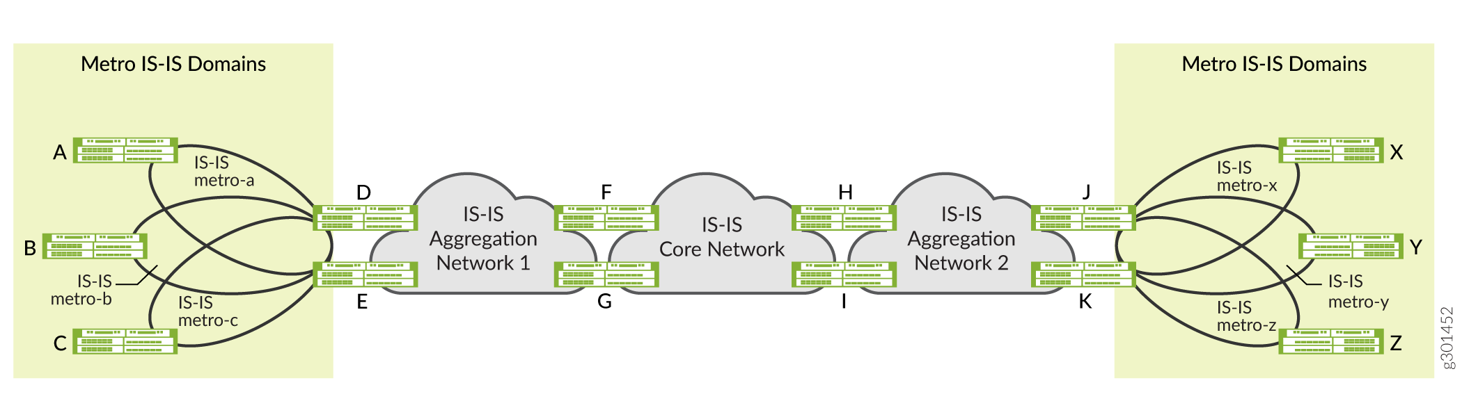
Figure 1 illustrates several benefits of configuring multiple IGP instances of IS-IS on the router. For example, Router F participates in two independent IS-IS instances. Router F treats IS-IS Aggregation Network-1 and IS-IS Core Network as two independent IGP domains, while at the same time redistributing routes between those domains. Network operators can use this flexibility to construct a hierarchy of IS-IS domains.
Figure 1 also illustrates the use of multiple IGP instances of IS-IS to separate metro networks into independent IS-IS flooding domains. In the example, routers D and E participate in the IS-IS metro-a, IS-IS metro-b, and IS-IS metro-c networks, as well as in IS-IS Aggregation Network-1. Routers D and E do not flood the different IS-IS domains with IS-IS advertisements. Instead they redistribute specific routes among the different IS-IS domains, which allows for more scalable metro deployments.
Multi-Instance IS-IS Overview
You can configure and run multiple independent IGP instances of IS-IS simultaneously on a router. These instances are associated with the default routing instance, and they install routes in the default routing table.Each IS-IS instance can also export the routes installed in the routing table by other IS-IS instances using the standard Junos OS routing policy configuration. By default, the routes installed by the different IS-IS instances have the same route preference.
Junos OS does not support configuring the same logical interface in multiple IGP instances of IS-IS.
In most deployment scenarios, only one IS-IS instance on a router installs a route for a given prefix. Therefore, you don't need to configure different route preferences for multiple IS-IS instances. However, for certain deployment scenarios where multiple IS-IS instances install the routes for the same prefix in the routing table, you can set a different route preference for the routes installed by other IS-IS instances. This allows the routing table to choose the routes with the best route preference and installs those routes in the forwarding table.
You can use the multiple IS-IS instance feature for both hierarchical and parallel deployments. In the case of hierarchical deployments, there are well-defined borders between the groups of routers participating in different IGP instances. In parallel deployments, different IGP instances (typically not more than two or three) span entire groups of routers. You can also have mixed deployments, with some domains in a hierarchical deployment running IGP instances in parallel.
You can configure multiple independent IGP instances of IS-IS by including the
isis-instance configuration statement at the [edit
protocols] hierarchy level. The configuration statements that you use at the
[edit protocols isis-instance igp-instance-name]
hierarchy level are the same as those available at the [edit protocols
isis] hierarchy level.
The isis-instance configuration statement is not supported at the
[edit routing-instances routing-instance-name
protocols] hierarchy level.
You can configure multiple independent IGP instances of OSPFv2 by including the
ospf-instance configuration statement at the [edit
protocols] hierarchy level. The configuration statements that you use at the
[edit protocols ospf-instance igp-instance-name]
hierarchy level are the same as those available at the [edit protocols
ospf] hierarchy level.
The ospf-instance configuration statement is not supported at the
[edit routing-instances routing-instance-name
protocols] hierarchy level.
You can configure and run multiple independent interior gateway protocol (IGP) instances of OSPFv2 with segment routing (SR) on a router. You can create two or more OSPF instances and apply SR-MPLS on each instance. Multiple instances of OSPF can advertise different prefix-segment identifiers (prefix-SIDs). Other instances can use these SIDs for making routing decisions.
Multi-instance OSPF combined with SR enhances network flexibility, scalability, and control over traffic engineering, especially in large and complex networks.
Example: Configure Independent IS-IS Instances in Metro Flooding Domains
Use this example to learn how to configure independent metro flooding domains running multiple IGP instances of IS-IS.
Overview
This example shows how to configure and run multiple independent IGP instances of IS-IS in metro flooding domains.
Topology
Figure 2 shows an example of metro flooding domains (metro-a and metro-b) running independent IGP instances of IS-IS. In the topology, routers R3 and R4 participate in metro IS-IS domains (IS-IS metro-a and IS-IS metro-b) and the IS-IS core network domain. Routers R3 and R4 do not flood the different IS-IS domains with IS-IS advertisements. Instead they redistribute specific routes among the different IS-IS domains, which allows for a more scalable metro deployment.

Requirements
This example uses the following hardware and software components:
- MX Series routers
- Junos OS Release 21.1R1 or later running on all devices
You must configure the network services mode as Enhanced IP. The Enhanced IP configuration ensures that the router uses enhanced mode capabilities.
[edit] user@CE1#set chassis network-services enhanced-ip
After you configure the enhanced-ip statement and commit the
configuration, the following warning message
appears,
prompting you to reboot the router:
'chassis' WARNING: Chassis configuration for network services has been changed. A system reboot is mandatory. Please reboot the system NOW. Continuing without a reboot might result in unexpected system behavior. commit complete
The reboot brings up the FPCs on the router.
Configuration
To configure and run multiple IGP instances of IS-IS on the router, perform these tasks:
CLI Quick Configuration
To quickly configure this example, copy the following commands, paste them into a text file, remove any line breaks, change any details necessary to match your network configuration, and then copy and paste the commands into the CLI at the [edit] hierarchy level.
Device R1
set interfaces ge-0/0/1 description R1-to-R4 set interfaces ge-0/0/1 unit 0 family inet address 192.168.1.1/24 set interfaces ge-0/0/1 unit 0 family iso set interfaces ge-0/0/2 description R1-to-R3 set interfaces ge-0/0/2 unit 0 family inet address 192.168.2.1/24 set interfaces ge-0/0/2 unit 0 family iso set interfaces lo0 unit 0 family inet address 192.168.100.1/32 set interfaces lo0 unit 0 family iso address 49.0002.0192.0168.0001.00 set protocols isis interface ge-0/0/1.0 level 2 metric 100 set protocols isis interface ge-0/0/1.0 level 1 disable set protocols isis interface ge-0/0/1.0 point-to-point set protocols isis interface ge-0/0/2.0 level 1 disable set protocols isis interface ge-0/0/2.0 level 2 metric 100 set protocols isis interface ge-0/0/2.0 point-to-point set protocols isis interface lo0.0 passive set routing-options router-id 192.168.100.1
Device R2
set interfaces ge-0/0/1 description R2-to-R3 set interfaces ge-0/0/1 unit 0 family inet address 192.168.3.1/24 set interfaces ge-0/0/1 unit 0 family iso set interfaces ge-0/0/2 description R2-to-R4 set interfaces ge-0/0/2 unit 0 family inet address 192.168.4.1/24 set interfaces ge-0/0/2 unit 0 family iso set interfaces lo0 unit 0 family inet address 192.168.100.2/32 set interfaces lo0 unit 0 family iso address 49.0002.0192.0168.0002.00 set protocols isis interface ge-0/0/1.0 level 1 disable set protocols isis interface ge-0/0/1.0 level 2 metric 100 set protocols isis interface ge-0/0/1.0 point-to-point set protocols isis interface ge-0/0/2.0 level 1 disable set protocols isis interface ge-0/0/2.0 level 2 metric 100 set protocols isis interface ge-0/0/2.0 point-to-point set protocols isis interface lo0.0 passive set routing-options router-id 192.168.100.2
Device R3
set interfaces ge-0/0/1 description R3-to-R2 set interfaces ge-0/0/1 unit 0 family inet address 192.168.3.2/24 set interfaces ge-0/0/1 unit 0 family iso set interfaces ge-0/0/2 description R3-to-R1 set interfaces ge-0/0/2 unit 0 family inet address 192.168.2.2/24 set interfaces ge-0/0/2 unit 0 family iso set interfaces ge-0/0/3 description R3-to-R5 set interfaces ge-0/0/3 unit 0 family inet address 192.168.6.1/24 set interfaces ge-0/0/3 unit 0 family iso set interfaces ge-0/0/4 description R3-to-R4 set interfaces ge-0/0/4 vlan-tagging set interfaces ge-0/0/4 unit 0 vlan-id 10 set interfaces ge-0/0/4 unit 0 family inet address 192.168.5.1/24 set interfaces ge-0/0/4 unit 0 family iso set interfaces ge-0/0/4 unit 1 vlan-id 11 set interfaces ge-0/0/4 unit 1 family inet address 192.168.9.1/24 set interfaces ge-0/0/4 unit 1 family iso set interfaces ge-0/0/4 unit 2 vlan-id 12 set interfaces ge-0/0/4 unit 2 family inet address 192.168.10.1/24 set interfaces ge-0/0/4 unit 2 family iso set interfaces lo0 unit 0 family inet address 192.168.100.3/32 set interfaces lo0 unit 0 family iso address 49.0002.0192.0168.0003.00 set policy-options policy-statement export-direct-loopback from protocol direct set policy-options policy-statement export-direct-loopback from route-filter 192.168.100.3/32 exact set policy-options policy-statement export-direct-loopback then accept set policy-options policy-statement export-isis from protocol isis set policy-options policy-statement export-isis from level 2 set policy-options policy-statement export-isis from route-filter 192.168.100.0/24 longer set policy-options policy-statement export-isis then accept set policy-options policy-statement export-isis-metro-a from igp-instance metro-a set policy-options policy-statement export-isis-metro-a from protocol isis set policy-options policy-statement export-isis-metro-a from level 2 set policy-options policy-statement export-isis-metro-a from route-filter 192.168.100.0/24 longer set policy-options policy-statement export-isis-metro-a then accept set policy-options policy-statement export-isis-metro-b from igp-instance metro-b set policy-options policy-statement export-isis-metro-b from protocol isis set policy-options policy-statement export-isis-metro-b from level 2 set policy-options policy-statement export-isis-metro-b from route-filter 192.168.100.0/24 longer set policy-options policy-statement export-isis-metro-b then accept set protocols isis interface ge-0/0/3.0 level 1 disable set protocols isis interface ge-0/0/3.0 level 2 metric 100 set protocols isis interface ge-0/0/3.0 point-to-point set protocols isis interface ge-0/0/4.0 level 1 disable set protocols isis interface ge-0/0/4.0 level 2 metric 100 set protocols isis interface ge-0/0/4.0 point-to-point set protocols isis interface lo0.0 passive set protocols isis export export-isis-metro-a set protocols isis export export-isis-metro-b set protocols isis-instance metro-b interface ge-0/0/1.0 level 1 disable set protocols isis-instance metro-b interface ge-0/0/1.0 level 2 metric 100 set protocols isis-instance metro-b interface ge-0/0/1.0 point-to-point set protocols isis-instance metro-b interface ge-0/0/4.2 level 1 disable set protocols isis-instance metro-b interface ge-0/0/4.2 level 2 metric 100 set protocols isis-instance metro-b interface ge-0/0/4.2 point-to-point set protocols isis-instance metro-b export export-isis set protocols isis-instance metro-b export export-direct-loopback set protocols isis-instance metro-b export export-isis-metro-a set protocols isis-instance metro-a interface ge-0/0/2.0 level 1 disable set protocols isis-instance metro-a interface ge-0/0/2.0 level 2 metric 100 set protocols isis-instance metro-a interface ge-0/0/2.0 point-to-point set protocols isis-instance metro-a interface ge-0/0/4.1 level 1 disable set protocols isis-instance metro-a interface ge-0/0/4.1 level 2 metric 100 set protocols isis-instance metro-a interface ge-0/0/4.1 point-to-point set protocols isis-instance metro-a export export-isis set protocols isis-instance metro-a export export-direct-loopback set protocols isis-instance metro-a export export-isis-metro-b set routing-options router-id 192.168.100.3
Device R4
set interfaces ge-0/0/1 description R4-to-R1 set interfaces ge-0/0/1 unit 0 family inet address 192.168.1.2/24 set interfaces ge-0/0/1 unit 0 family iso set interfaces ge-0/0/2 description R4-to-R2 set interfaces ge-0/0/2 unit 0 family inet address 192.168.4.2/24 set interfaces ge-0/0/2 unit 0 family iso set interfaces ge-0/0/3 description R4-to-R6 set interfaces ge-0/0/3 unit 0 family inet address 192.168.7.1/24 set interfaces ge-0/0/3 unit 0 family iso set interfaces ge-0/0/4 description R4-to-R3 set interfaces ge-0/0/4 vlan-tagging set interfaces ge-0/0/4 unit 0 vlan-id 10 set interfaces ge-0/0/4 unit 0 family inet address 192.168.5.2/24 set interfaces ge-0/0/4 unit 0 family iso set interfaces ge-0/0/4 unit 1 vlan-id 11 set interfaces ge-0/0/4 unit 1 family inet address 192.168.9.2/24 set interfaces ge-0/0/4 unit 1 family iso set interfaces ge-0/0/4 unit 2 vlan-id 12 set interfaces ge-0/0/4 unit 2 family inet address 192.168.10.2/24 set interfaces ge-0/0/4 unit 2 family iso set interfaces lo0 unit 0 family inet address 192.168.100.4/32 set interfaces lo0 unit 0 family iso address 49.0002.0192.0168.0004.00 set policy-options policy-statement export-direct-loopback from protocol direct set policy-options policy-statement export-direct-loopback from route-filter 192.168.100.4/32 exact set policy-options policy-statement export-direct-loopback then accept set policy-options policy-statement export-isis from protocol isis set policy-options policy-statement export-isis from level 2 set policy-options policy-statement export-isis from route-filter 192.168.100.0/24 longer set policy-options policy-statement export-isis then accept set policy-options policy-statement export-isis-metro-a from igp-instance metro-a set policy-options policy-statement export-isis-metro-a from protocol isis set policy-options policy-statement export-isis-metro-a from level 2 set policy-options policy-statement export-isis-metro-a from route-filter 192.168.100.0/24 longer set policy-options policy-statement export-isis-metro-a then accept set policy-options policy-statement export-isis-metro-b from igp-instance metro-b set policy-options policy-statement export-isis-metro-b from protocol isis set policy-options policy-statement export-isis-metro-b from level 2 set policy-options policy-statement export-isis-metro-b from route-filter 192.168.100.0/24 longer set policy-options policy-statement export-isis-metro-b then accept set protocols isis interface ge-0/0/3.0 level 1 disable set protocols isis interface ge-0/0/3.0 level 2 metric 100 set protocols isis interface ge-0/0/3.0 point-to-point set protocols isis interface ge-0/0/4.0 level 1 disable set protocols isis interface ge-0/0/4.0 level 2 metric 100 set protocols isis interface ge-0/0/4.0 point-to-point set protocols isis interface lo0.0 passive set protocols isis export export-isis-metro-a set protocols isis export export-isis-metro-b set protocols isis-instance metro-a interface ge-0/0/1.0 level 1 disable set protocols isis-instance metro-a interface ge-0/0/1.0 level 2 metric 100 set protocols isis-instance metro-a interface ge-0/0/1.0 point-to-point set protocols isis-instance metro-a interface ge-0/0/4.1 level 1 disable set protocols isis-instance metro-a interface ge-0/0/4.1 level 2 metric 100 set protocols isis-instance metro-a interface ge-0/0/4.1 point-to-point set protocols isis-instance metro-a export export-isis set protocols isis-instance metro-a export export-direct-loopback set protocols isis-instance metro-a export export-isis-metro-b set protocols isis-instance metro-b interface ge-0/0/2.0 level 1 disable set protocols isis-instance metro-b interface ge-0/0/2.0 level 2 metric 100 set protocols isis-instance metro-b interface ge-0/0/2.0 point-to-point set protocols isis-instance metro-b interface ge-0/0/4.2 level 1 disable set protocols isis-instance metro-b interface ge-0/0/4.2 level 2 metric 100 set protocols isis-instance metro-b interface ge-0/0/4.2 point-to-point set protocols isis-instance metro-b export export-isis set protocols isis-instance metro-b export export-direct-loopback set protocols isis-instance metro-b export export-isis-metro-a set routing-options router-id 192.168.100.4
Device R5
set interfaces ge-0/0/2 description R5-to-R6 set interfaces ge-0/0/2 unit 0 family inet address 192.168.8.1/24 set interfaces ge-0/0/2 unit 0 family iso set interfaces ge-0/0/3 description R5-to-R3 set interfaces ge-0/0/3 unit 0 family inet address 192.168.6.2/24 set interfaces ge-0/0/3 unit 0 family iso set interfaces lo0 unit 0 family inet address 192.168.100.5/32 set interfaces lo0 unit 0 family iso address 49.0002.0192.0168.0005.00 set protocols isis interface ge-0/0/2.0 level 1 disable set protocols isis interface ge-0/0/2.0 level 2 metric 100 set protocols isis interface ge-0/0/2.0 point-to-point set protocols isis interface ge-0/0/3.0 level 1 disable set protocols isis interface ge-0/0/3.0 level 2 metric 100 set protocols isis interface ge-0/0/3.0 point-to-point set protocols isis interface lo0.0 passive set routing-options router-id 192.168.100.5
Device R6
set interfaces ge-0/0/2 description R6-to-R5 set interfaces ge-0/0/2 unit 0 family inet address 192.168.8.2/24 set interfaces ge-0/0/2 unit 0 family iso set interfaces ge-0/0/3 description R6-to-R4 set interfaces ge-0/0/3 unit 0 family inet address 192.168.7.2/24 set interfaces ge-0/0/3 unit 0 family iso set interfaces lo0 unit 0 family inet address 192.168.100.6/32 set interfaces lo0 unit 0 family iso address 49.0002.0192.0168.0006.00 set protocols isis interface ge-0/0/2.0 level 1 disable set protocols isis interface ge-0/0/2.0 level 2 metric 100 set protocols isis interface ge-0/0/2.0 point-to-point set protocols isis interface ge-0/0/3.0 level 1 disable set protocols isis interface ge-0/0/3.0 level 2 metric 100 set protocols isis interface ge-0/0/3.0 point-to-point set protocols isis interface lo0.0 passive set routing-options router-id 192.168.100.6
Configure R1
Step-by-Step Procedure
The following example requires you to navigate various levels in the configuration hierarchy. For information about navigating the CLI, see Using the CLI Editor in Configuration Mode in the CLI User Guide.
You can use the steps in this example to also configure the R2, R5, and R6 routers. See CLI Quick Configuration and Figure 2 to understand the interface IDs, IP addresses, and the loopback addresses used on these routers.
To configure R1:
-
Configure the interfaces to enable IP (
inet) and ISO family support.user@R1# set interfaces ge-0/0/1 description R1-to-R4 user@R1# set interfaces ge-0/0/1 unit 0 family inet address 192.168.1.1/24 user@R1# set interfaces ge-0/0/1 unit 0 family iso user@R1# set interfaces ge-0/0/2 description R1-to-R3 user@R1# set interfaces ge-0/0/2 unit 0 family inet address 192.168.2.1/24 user@R1# set interfaces ge-0/0/2 unit 0 family iso
-
Create the loopback interface and configure the IP and NET addresses.
user@R1# set interfaces lo0 unit 0 family inet address 192.168.100.1/32 user@R1# set interfaces lo0 unit 0 family iso address 49.0002.0192.0168.0001.00
-
Configure routing options to identify the router in the domain.
user@R1# set routing-options router-id 192.168.100.1
-
Enable IS-IS on the interfaces.
user@R1# set protocols isis interface ge-0/0/1.0 level 2 metric 100 user@R1# set protocols isis interface ge-0/0/1.0 level 1 disable user@R1# set protocols isis interface ge-0/0/1.0 point-to-point user@R1# set protocols isis interface ge-0/0/2.0 level 1 disable user@R1# set protocols isis interface ge-0/0/2.0 level 2 metric 100 user@R1# set protocols isis interface ge-0/0/2.0 point-to-point user@R1# set protocols isis interface lo0.0 passive
Results
From configuration mode,
confirm
your configuration by entering the show interfaces,
show routing-options, and show
protocols commands. If the output does not display the intended
configuration, repeat the instructions in this example to correct the
configuration.
interfaces {
ge-0/0/1 {
description R1-to-R4;
unit 0 {
family inet {
address 192.168.1.1/24;
}
family iso;
}
}
ge-0/0/2 {
description R1-to-R3;
unit 0 {
family inet {
address 192.168.2.1/24;
}
family iso;
}
}
lo0 {
unit 0 {
family inet {
address 192.168.100.1/32;
}
family iso {
address 49.0002.0192.0168.0001.00;
}
}
}
}
protocols {
isis {
interface ge-0/0/1.0 {
level 2 metric 100;
level 1 disable;
point-to-point;
}
interface ge-0/0/2.0 {
level 1 disable;
level 2 metric 100;
point-to-point;
}
interface lo0.0 {
passive;
}
}
}
routing-options {
router-id 192.168.100.1;
}
Configure R3
Step-by-Step Procedure
The following example requires you to navigate various levels in the configuration hierarchy. For information about navigating the CLI, see Using the CLI Editor in Configuration Mode in the CLI User Guide.
You can use the steps in this example to also configure the R4 router. See CLI Quick Configuration and Figure 2 to understand the interface IDs, IP addresses, and the loopback address used on the router.
To configure R3:
-
Configure the interfaces connecting to R1, R2, and R5 to enable IP and ISO family support.
user@R3# set interfaces ge-0/0/1 description R3-to-R2 user@R3# set interfaces ge-0/0/1 unit 0 family inet address 192.168.3.2/24 user@R3# set interfaces ge-0/0/1 unit 0 family iso user@R3# set interfaces ge-0/0/2 description R3-to-R1 user@R3# set interfaces ge-0/0/2 unit 0 family inet address 192.168.2.2/24 user@R3# set interfaces ge-0/0/2 unit 0 family iso user@R3# set interfaces ge-0/0/3 description R3-to-R5 user@R3# set interfaces ge-0/0/3 unit 0 family inet address 192.168.6.1/24 user@R3# set interfaces ge-0/0/3 unit 0 family iso
-
Configure three subinterfaces (logical interfaces) connecting R3 and R4 (one IS-IS standard instance and two IS-IS metro instances (IS-IS metro-a and IS-IS metro-b)).
Note:The standard IS-IS instance refers to the IS-IS IGP instance configured at the [
edit protocols isis] hierarchy level.user@R3# set interfaces ge-0/0/4 description R3-to-R4 user@R3# set interfaces ge-0/0/4 vlan-tagging user@R3# set interfaces ge-0/0/4 unit 0 vlan-id 10 user@R3# set interfaces ge-0/0/4 unit 0 family inet address 192.168.5.1/24 user@R3# set interfaces ge-0/0/4 unit 0 family iso user@R3# set interfaces ge-0/0/4 unit 1 vlan-id 11 user@R3# set interfaces ge-0/0/4 unit 1 family inet address 192.168.9.1/24 user@R3# set interfaces ge-0/0/4 unit 1 family iso user@R3# set interfaces ge-0/0/4 unit 2 vlan-id 12 user@R3# set interfaces ge-0/0/4 unit 2 family inet address 192.168.10.1/24 user@R3# set interfaces ge-0/0/4 unit 2 family iso
-
Create the loopback interface and configure the IP and NET addresses.
user@R3# set interfaces lo0 unit 0 family inet address 192.168.100.3/32
user@R3# set interfaces lo0 unit 0 family iso address 49.0002.0192.0168.0003.00
-
Configure policies to redistribute loopback addresses of IS-IS metro-instance (IS-IS metro-a and IS-IS metro-b) and IS-IS standard-instance (core network) routers, so that the routes can be distributed across IS-IS domains as required.
-
Configure policies to distribute the loopback address of R3.
user@R3# set policy-options policy-statement export-direct-loopback from protocol direct
user@R3# set policy-options policy-statement export-direct-loopback from route-filter 192.168.100.3/32 exact
user@R3# set policy-options policy-statement export-direct-loopback then accept
-
Configure policies to distribute the loopback addresses of the R5 and R6 routers (standard IS-IS instance).
user@R3# set policy-options policy-statement export-isis from protocol isis
user@R3# set policy-options policy-statement export-isis from level 2
user@R3# set policy-options policy-statement export-isis from route-filter 192.168.100.0/24 longer
user@R3# set policy-options policy-statement export-isis then accept
-
Configure policies to distribute the loopback addresses of R1 (IS-IS metro-a instance).
user@R3# set policy-options policy-statement export-isis-metro-a from igp-instance metro-a
user@R3# set policy-options policy-statement export-isis-metro-a from protocol isis
user@R3# set policy-options policy-statement export-isis-metro-a from level 2
user@R3# set policy-options policy-statement export-isis-metro-a from route-filter 192.168.100.0/24 longer
user@R3# set policy-options policy-statement export-isis-metro-a then accept
-
Configure policies to distribute the loopback addresses of R2 (IS-IS metro-b instance).
user@R3# set policy-options policy-statement export-isis-metro-b from igp-instance metro-b
user@R3# set policy-options policy-statement export-isis-metro-b from protocol isis
user@R3# set policy-options policy-statement export-isis-metro-b from level 2
user@R3# set policy-options policy-statement export-isis-metro-b from route-filter 192.168.100.0/24 longer
user@R3# set policy-options policy-statement export-isis-metro-b then accept
-
-
Enable IS-IS on the standard-instance interface (connecting R3 to R5) and on the subinterface (connecting R3 to R4).
user@R3# set protocols isis interface ge-0/0/3.0 level 1 disable
user@R3# set protocols isis interface ge-0/0/3.0 level 2 metric 100
user@R3# set protocols isis interface ge-0/0/3.0 point-to-point
user@R3# set protocols isis interface ge-0/0/4.0 level 1 disable
user@R3# set protocols isis interface ge-0/0/4.0 level 2 metric 100
user@R3# set protocols isis interface ge-0/0/4.0 point-to-point
user@R3# set protocols isis interface lo0.0 passive
-
Configure IS-IS to export loopback addresses from IS-IS metro-a and IS-IS metro-b instances to the IS-IS standard instance. This configuration distributes specific routes instead of flooding the entire metro domain.
user@R3# set protocols isis export export-isis-metro-a
user@R3# set protocols isis export export-isis-metro-b
-
Enable IS-IS on the IS-IS metro-b instance interface (connecting R3 to R2) and on the subinterface (R3 to R4).
user@R3# set protocols isis-instance metro-b interface ge-0/0/1.0 level 1 disable
user@R3# set protocols isis-instance metro-b interface ge-0/0/1.0 level 2 metric 100
user@R3# set protocols isis-instance metro-b interface ge-0/0/1.0 point-to-point
user@R3# set protocols isis-instance metro-b interface ge-0/0/4.2 level 1 disable
user@R3# set protocols isis-instance metro-b interface ge-0/0/4.2 level 2 metric 100
user@R3# set protocols isis-instance metro-b interface ge-0/0/4.2 point-to-point
-
Configure IS-IS to export the loopback addresses of IS-IS metro-a and standard IS-IS instances to the IS-IS metro-b instance. This configuration distributes specific routes instead of flooding the entire standard IS-IS instances and metro-a domain instances.
user@R3# set protocols isis-instance metro-b export export-isis
user@R3# set protocols isis-instance metro-b export export-direct-loopback
user@R3# set protocols isis-instance metro-b export export-isis-metro-a
-
Enable IS-IS on the IS-IS metro-a instance interface (connecting R3 to R1) and on the subinterface (R3 to R4).
user@R3# set protocols isis-instance metro-a interface ge-0/0/2.0 level 1 disable
user@R3# set protocols isis-instance metro-a interface ge-0/0/2.0 level 2 metric 100
user@R3# set protocols isis-instance metro-a interface ge-0/0/2.0 point-to-point
user@R3# set protocols isis-instance metro-a interface ge-0/0/4.1 level 1 disable
user@R3# set protocols isis-instance metro-a interface ge-0/0/4.1 level 2 metric 100
user@R3# set protocols isis-instance metro-a interface ge-0/0/4.1 point-to-point
-
Configure IS-IS to export the loopback addresses of IS-IS metro-b and standard IS-IS instances to the IS-IS metro-a instance. This configuration distributes specific routes instead of flooding the entire standard IS-IS instances and metro-b domain instances.
user@R3# set protocols isis-instance metro-a export export-isis
user@R3# set protocols isis-instance metro-a export export-direct-loopback
user@R3# set protocols isis-instance metro-a export export-isis-metro-b
-
Configure routing options to identify the router in the domain.
user@R3# set routing-options router-id 192.168.100.3
Results
From configuration mode,
confirm
your configuration by entering the show interfaces,
show routing-options, and show protocols
commands. If the output does not display the intended configuration, repeat the
instructions in this example to correct the configuration.
interfaces {
    ge-0/0/1 {
        description R3-to-R2;
        unit 0 {
            family inet {
                address 192.168.3.2/24;
            }
            family iso;
        }
    }
    ge-0/0/2 {
        description R3-to-R1;
        unit 0 {
            family inet {
                address 192.168.2.2/24;
            }
            family iso;
        }
    }
    ge-0/0/3 {
        description R3-to-R5;
        unit 0 {
            family inet {
                address 192.168.6.1/24;
            }
            family iso;
        }
    }
    ge-0/0/4 {
        description R3-to-R4;
        vlan-tagging;
        unit 0 {
            vlan-id 10;
            family inet {
                address 192.168.5.1/24;
            }
            family iso;
        }
        unit 1 {
            vlan-id 11;
            family inet {
                address 192.168.9.1/24;
            }
            family iso;
        }
        unit 2 {
            vlan-id 12;
            family inet {
                address 192.168.10.1/24;
            }
            family iso;
        }
    }
    lo0 {
        unit 0 {
            family inet {
                address 192.168.100.3/32;
            }
            family iso {
                address 49.0002.0192.0168.0003.00;
            }
        }
    }
}
policy-options {
    policy-statement export-direct-loopback {
        from {
            protocol direct;
            route-filter 192.168.100.3/32 exact;
        }
        then accept;
    }
    policy-statement export-isis {
        from {
            protocol isis;
            level 2;
            route-filter 192.168.100.0/24 longer;
        }
        then accept;
    }
    policy-statement export-isis-metro-a {
        from {
            igp-instance metro-a;
            protocol isis;
            level 2;
            route-filter 192.168.100.0/24 longer;
        }
        then accept;
    }
    policy-statement export-isis-metro-b {
        from {
            igp-instance metro-b;
            protocol isis;
            level 2;
            route-filter 192.168.100.0/24 longer;
        }
        then accept;
    }
}
protocols {
    isis {
        interface ge-0/0/3.0 {
            level 1 disable;
            level 2 metric 100;
            point-to-point;
        }
        interface ge-0/0/4.0 {
            level 1 disable;
            level 2 metric 100;
            point-to-point;
        }
        interface lo0.0 {
            passive;
        }
        export [ export-isis-metro-a export-isis-metro-b ];
    }
    isis-instance metro-b {
        interface ge-0/0/1.0 {
            level 1 disable;
            level 2 metric 100;
            point-to-point;
        }
        interface ge-0/0/4.2 {
            level 1 disable;
            level 2 metric 100;
            point-to-point;
        }
        export [ export-isis export-direct-loopback export-isis-metro-a ];
    }
    isis-instance metro-a {
        interface ge-0/0/2.0 {
            level 1 disable;
            level 2 metric 100;
            point-to-point;
        }
        interface ge-0/0/4.1 {
            level 1 disable;
            level 2 metric 100;
            point-to-point;
        }
        export [ export-isis export-direct-loopback export-isis-metro-b ];
    }
}
routing-options {
    router-id 192.168.100.3;
}
Verification
To verify that the configuration is working properly, perform the following tasks:
- Verify IS-IS Advertisements
- Verify the Routing Table
- Verify the Routes in the IS-IS Routing Table
- Verify IS-IS Interfaces
Verify IS-IS Advertisements
Purpose
Verify the IS-IS advertisement entries in the IS-IS link-state database (LSDB), which contains data about PDU packets.
Action
From operational mode, run the show isis database level 2
command.
On R3
user@R3>show isis database level 2

IS-IS level 2 link-state database:
LSP ID                      Sequence Checksum Lifetime Attributes
R6.00-00                       0x75d   0x1ff7     1181 L1 L2
R5.00-00                       0x75b   0xffdc      741 L1 L2
R4.00-00                       0x780    0x4e1      552 L1 L2
R3.00-00                       0x7f0   0x8643      496 L1 L2
  4 LSPs
user@R3>show isis database level 2 igp-instance metro-a
IS-IS level 2 link-state database:
LSP ID                      Sequence Checksum Lifetime Attributes
R1.00-00                       0x136   0x46e5     1046 L1 L2
R4.00-00                       0x781   0xf65e      768 L1 L2
R3.00-00                       0x7f2   0x871b      764 L1 L2
  3 LSPs
user@R3>show isis database level 2 igp-instance metro-b
IS-IS level 2 link-state database:
LSP ID                      Sequence Checksum Lifetime Attributes
R2.00-00                       0x13a   0x7997     1013 L1 L2
R4.00-00                       0x781   0x86ba      771 L1 L2
R3.00-00                       0x7f2   0x1288      510 L1 L2
  3 LSPs
On R1
user@R1>show isis database level 2

IS-IS level 2 link-state database:
LSP ID                      Sequence Checksum Lifetime Attributes
R1.00-00                       0x136   0x46e5      851 L1 L2
R4.00-00                       0x781   0xf65e      571 L1 L2
R3.00-00                       0x7f2   0x871b      565 L1 L2
  3 LSPs
Meaning
This output on R3 illustrates that R3 sees the IS-IS advertisements from R4, R5, and R6 which is standard IS-IS instance. R3 also sees the IS-IS advertisements from R1 (IS-IS metro-a), R2 (IS-IS metro-b), and R4 (both IS-IS metro-a and IS-IS metro-b). Thus, you can see that R3 is a common router that redistributes IS-IS routes among the IS-IS metro-a instance, the IS-IS metro-b instance, and the standard IS-IS instance (core network).
The output on R1 illustrates that R1 sees the IS-IS advertisements only from R3 and R4. R1 does not see any IS-IS advertisements from R2. Thus, you see that IS-IS metro-a and IS-IS metro-b are separate IS-IS flooding domains. You can use this property to build more scalable networks.
Verify the Routing Table
Purpose
Verify the route entries in the routing table.
Action
From operational mode, run the show route table inet.0
route-destination address extensive
command.
On R3
user@R3>show route table inet.0 192.168.100.1 extensive

inet.0: 28 destinations, 28 routes (28 active, 0 holddown, 0 hidden)
192.168.100.1/32 (1 entry, 1 announced)
TSI:
KRT in-kernel 192.168.100.1/32 -> {192.168.2.1}
IS-IS level 1, LSP fragment 0
IS-IS level 2, LSP fragment 0
IS-IS level 1, LSP fragment 0
IS-IS level 2, LSP fragment 0
        *IS-IS  Preference: 18
                Level: 2
                Next hop type: Router, Next hop index: 601
                Address: 0xc5b21cc
                Next-hop reference count: 2
                Next hop: 192.168.2.1 via ge-0/0/2.0, selected
                Session Id: 0x140
                State: <Active Int>
                Age: 2d 18:10:36        Metric: 63
                Validation State: unverified
                ORR Generation-ID: 0
                Task: IS-IS-metro-a
                Announcement bits (3): 0-KRT 2-IS-IS 10-IS-IS-metro-b
                AS path: I
                Thread: junos-main
user@R3>show route table inet.0 192.168.100.2 extensive
inet.0: 28 destinations, 28 routes (28 active, 0 holddown, 0 hidden)
192.168.100.2/32 (1 entry, 1 announced)
TSI:
KRT in-kernel 192.168.100.2/32 -> {192.168.3.1}
IS-IS level 1, LSP fragment 0
IS-IS level 2, LSP fragment 0
IS-IS level 1, LSP fragment 0
IS-IS level 2, LSP fragment 0
        *IS-IS  Preference: 18
                Level: 2
                Next hop type: Router, Next hop index: 602
                Address: 0xc5b2234
                Next-hop reference count: 2
                Next hop: 192.168.3.1 via ge-0/0/1.0, selected
                Session Id: 0x141
                State: <Active Int>
                Age: 2d 18:18:48        Metric: 63
                Validation State: unverified
                ORR Generation-ID: 0
                Task: IS-IS-metro-b
                Announcement bits (3): 0-KRT 2-IS-IS 4-IS-IS-metro-a
                AS path: I
                Thread: junos-main
Meaning
The output illustrates that the loopback address of R1 (192.168.100.1) is mapped to the IS-IS metro-a instance (IS-IS-metro-a) and the loopback address of R2 (192.168.100.2) is mapped to the IS-IS metro-b instance (IS-IS-metro-b) as configured in R3.
Verify the Routes in the IS-IS Routing Table
Purpose
Verify the routes in the IS-IS routing table.
Action
From operational mode, run the show isis route command.
On R3
user@R3>show isis route
IS-IS routing table             Current version: L1: 1885 L2: 1956
IPv4/IPv6 Routes
----------------
Prefix             L Version   Metric Type Interface       NH   Via                 Backup Score
192.168.7.0/24     2    1956      126 int  ge-0/0/4.0      IPV4 R4
192.168.8.0/24     2    1956      126 int  ge-0/0/3.0      IPV4 R5
192.168.100.4/32   2    1956       63 int  ge-0/0/4.0      IPV4 R4
192.168.100.5/32   2    1956       63 int  ge-0/0/3.0      IPV4 R5
192.168.100.6/32   2    1956      126 int  ge-0/0/3.0      IPV4 R5
                                           ge-0/0/4.0      IPV4 R4
user@R3>show isis route igp-instance metro-a
 IS-IS routing table             Current version: L1: 1889 L2: 1961
IPv4/IPv6 Routes
----------------
Prefix             L Version   Metric Type Interface       NH   Via                 Backup Score
192.168.1.0/24     2    1961      126 int  ge-0/0/4.1      IPV4 R4
                                           ge-0/0/2.0      IPV4 R1
192.168.100.1/32   2    1961       63 int  ge-0/0/2.0      IPV4 R1
user@R3>show isis route igp-instance metro-b
 IS-IS routing table             Current version: L1: 1892 L2: 1949
IPv4/IPv6 Routes
----------------
Prefix             L Version   Metric Type Interface       NH   Via                 Backup Score
192.168.4.0/24     2    1949      126 int  ge-0/0/4.2      IPV4 R4
                                           ge-0/0/1.0      IPV4 R2
192.168.100.2/32   2    1949       63 int  ge-0/0/1.0      IPV4 R2
On R1
user@R1>show isis route
IS-IS routing table             Current version: L1: 313 L2: 392
IPv4/IPv6 Routes
----------------
Prefix             L Version   Metric Type Interface       NH   Via                 Backup Score
192.168.9.0/24     2     392      126 int  ge-0/0/2.0      IPV4 R3
                                           ge-0/0/1.0      IPV4 R4
192.168.100.2/32   2     392      126 int  ge-0/0/2.0      IPV4 R3
                                           ge-0/0/1.0      IPV4 R4
192.168.100.3/32   2     392       73 int  ge-0/0/2.0      IPV4 R3
192.168.100.4/32   2     392       73 int  ge-0/0/1.0      IPV4 R4
192.168.100.5/32   2     392      126 int  ge-0/0/2.0      IPV4 R3
                                           ge-0/0/1.0      IPV4 R4
192.168.100.6/32   2     392      126 int  ge-0/0/2.0      IPV4 R3
                                           ge-0/0/1.0      IPV4 R4
Meaning
The output on R3 shows the loopback addresses and the IS-IS instance mapping information of R1, R2, R4, R5, and R6.
The output on R1 shows the loopback addresses of R2, R3, R4, R5, and R6.
Verify IS-IS Interfaces
Purpose
Verify the status information about IS-IS-enabled interfaces.
Action
From operational mode, run the show isis interface command.
On R3
user@R3>show isis interface
IS-IS interface database:
Interface             L CirID Level 1 DR        Level 2 DR        L1/L2 Metric
ge-0/0/3.0            2   0x1 Disabled          Point to Point         10/100
ge-0/0/4.0            2   0x1 Disabled          Point to Point         10/100
lo0.0                 3   0x1 Passive           Passive                 0/0
user@R3>show isis interface igp-instance metro-a
IS-IS interface database:
Interface             L CirID Level 1 DR        Level 2 DR        L1/L2 Metric
ge-0/0/2.0            2   0x1 Disabled          Point to Point         10/100
ge-0/0/4.1            2   0x1 Disabled          Point to Point         10/100
user@R3>show isis interface igp-instance metro-b
IS-IS interface database:
Interface             L CirID Level 1 DR        Level 2 DR        L1/L2 Metric
ge-0/0/1.0            2   0x1 Disabled          Point to Point         10/100
ge-0/0/4.2            2   0x1 Disabled          Point to Point         10/100
On R1
user@R1>show isis interface
IS-IS interface database:
Interface             L CirID Level 1 DR        Level 2 DR        L1/L2 Metric
ge-0/0/1.0            2   0x1 Disabled          Point to Point         10/100
ge-0/0/2.0            2   0x1 Disabled          Point to Point         10/100
lo0.0                 3   0x1 Passive           Passive                 0/0
Meaning
The output shows the interfaces mapped to different IS-IS instances.
Example: Configure Multiple Independent Instances of OSPFv2 with Segment Routing
Use this example to configure multiple IGP instances of OSPFv2 with segment routing.
Our content testing team has validated and updated this example.
|
Reading Time |
30 minutes |
|
Configuration Time |
20 minutes |
- Example Prerequisites
- Before You Begin
- Functional Overview
- Topology Overview
- Topology Illustration
- R2 Configuration Steps
- Verification
- Appendix 1: Set Commands on All Devices
Example Prerequisites
|
Hardware requirements |
Three MX Series routers. |
|
Software requirements |
Junos OS Release 24.4R1 or later running on all devices. |
Before You Begin
|
Benefits |
Configuring multiple independent instances of OSPFv2 with segment routing enhances network flexibility, scalability, and control over traffic engineering, especially in large and complex networks. |
|
Know more |
Functional Overview
|
Technologies used |
|
|
Primary verification tasks |
|
Topology Overview
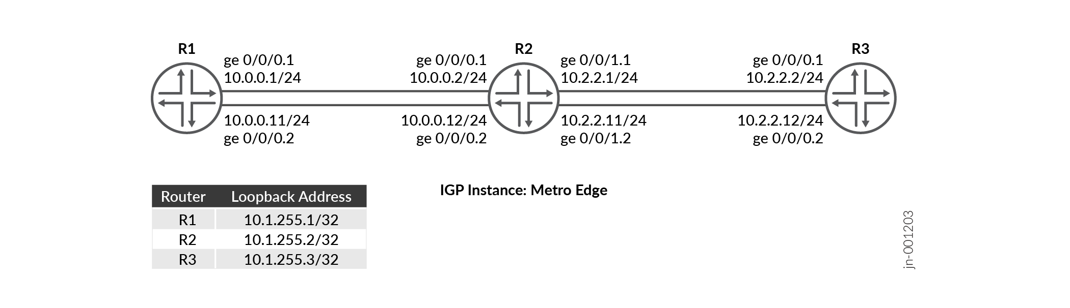
This configuration example depicts three devices R1, R2, and R3. There are two
sub-interfaces configured between device R1 and device R2 and between device R2 and
device R3. Each device runs multiple OSPF instances with segment routing enabled. We
configure SR-MPLS to provide path control through the network. There are OSPF
instances named metro-edge running on each of the two subinterfaces
of the devices.
|
Hostname |
Role |
Function |
|---|---|---|
|
R1, R2, and R3 |
The devices have multi-instance OSPF configured on the subinterfaces, with segment routing enabled. |
The devices participate in OSPF multi-instances, advertise routes, and forward traffic using prefix-SIDs to other devices. |
Topology Illustration
R2 Configuration Steps
For complete sample configurations on R2, see: Appendix 1: Set Commands on All Devices
This section highlights the main configuration tasks needed to configure the R2 device for this example.
-
Configure the basic device settings such as hostname,
enhanced-ipmode, IPv4 addresses on the logical units of the device interfaces.Configure the loopback interface with an IP address and enable MPLS.
Configure the router ID and autonomous system (AS) number to propagate routing information within a set of routing devices that belong to the same AS.
Enable VLAN tagging and configure the logical units of both the interfaces with different VLAN IDs.
Enable MPLS on each logical unit. Configure the maximum number of MPLS labels that can be applied to outgoing packets on logical units of each interface.
Define a policy to load balance packets and apply the per-packet policy to enable load balancing of traffic.
Configure a policy statement that matches routes based on the exact prefix and assign a segment identifier to the matched route.
Configure MPLS traffic engineering, segment routing global block (SRGB) label range at the
edit protocol mplshierarchy level to ensure the labels are more predictable across segment routing domain, MPLS label range to assign labels from the configured srgb labels for the links.[edit] set system host-name R2 set chassis network-services enhanced-ip set interfaces ge-0/0/0 unit 1 family inet address 10.0.0.2/24 set interfaces ge-0/0/0 unit 2 family inet address 10.0.0.12/24 set interfaces ge-0/0/1 unit 1 family inet address 10.2.2.1/24 set interfaces ge-0/0/1 unit 2 family inet address 10.2.2.11/24
[edit]
set interfaces lo0 unit 0 family inet address 10.1.255.2/32
set interfaces lo0 unit 0 family mpls
[edit]
set routing-options router-id 10.1.255.2
set routing-options autonomous-system 100
[edit]
set interfaces ge-0/0/0 vlan-tagging
set interfaces ge-0/0/0 unit 1 vlan-id 1
set interfaces ge-0/0/0 unit 2 vlan-id 2
set interfaces ge-0/0/1 vlan-tagging
set interfaces ge-0/0/1 unit 1 vlan-id 1
set interfaces ge-0/0/1 unit 2 vlan-id 2
[edit]
set interfaces ge-0/0/0 unit 1 family mpls maximum-labels 5
set interfaces ge-0/0/0 unit 2 family mpls maximum-labels 5
set interfaces ge-0/0/1 unit 1 family mpls maximum-labels 5
set interfaces ge-0/0/1 unit 2 family mpls maximum-labels 5
[edit]
set policy-options policy-statement pplb then load-balance per-packet
set policy-options policy-statement pplb then accept
set routing-options forwarding-table export pplb
[edit]
set policy-options policy-statement prefix-sid term 1 from route-filter 10.1.255.2/32 exact
set policy-options policy-statement prefix-sid term 1 then prefix-segment index 1001
set policy-options policy-statement prefix-sid term 1 then accept
[edit]
set protocols mpls traffic-engineering
set protocols mpls label-range srgb-label-range 800000 879999
set protocols mpls label-range static-label-range 60001 100000
set protocols mpls interface all
set protocols mpls interface fxp0.0 disable
Configure the
ospf-instancemetro-edgeon the subinterfaces (connecting from R2 to R1 and from R2 to R3).[edit] set protocols ospf-instance metro-edge area 0.0.0.0 interface all
Enable the OSPF
metro-edgeinstance to use segment routing with prefix-sids.[edit] set protocols ospf-instance metro-edge source-packet-routing prefix-segment prefix-sid
- Configure the IPv4 index value of the node
segment.
[edit]
set protocols ospf-instance metro-edge source-packet-routing node-segment ipv4-index 1
Configure the loopback address of the OSPF
metro-edgeinstance as passive and disable the management interface (fxp0.0).[edit] set protocols ospf-instance metro-edge area 0.0.0.0 interface lo0.0 passive set protocols ospf-instance metro-edge area 0.0.0.0 interface fxp0.0 disable
Verification
| Command | Verification Task |
|---|---|
| show route protocol ospf table inet.0 extensive |
|
| show ospf spring sid-database igp-instance igp-instance | Verify the OSPF segment routing database for the OSPF instance. |
| show ospf neighbor igp-instance igp-instance | Verify neighbors for the specific OSPF instance. |
| show ospf database igp-instance igp-instance |
Verify the OSPF advertisement entries in the OSPF link-state database (LSDB) associated with the IGP instance. |
| show ospf interface igp-instance igp-instance | Verify the interfaces mapped to the IGP instance. |
| show ospf route igp-instance igp-instance | Verify the routes and OSPF instance mapping information of R1 and R3. |
- Verify the Routing Table
- Verify OSPF Advertisements
- Verify the Routes in the OSPF Routing Table
- Verify the OSPF segment routing database
- Verify the OSPF Interfaces
- Verify the OSPF Neighbor
Verify the Routing Table
Purpose
Verify the route entries in the routing table
Action
From operational mode, run the show route table inet.0
route-destination address extensive command.
user@R2>show route protocol ospf table inet.0 10.1.255.1 extensive
inet.0: 19 destinations, 21 routes (19 active, 0 holddown, 0 hidden)
10.1.255.1/32 (1 entry, 1 announced)
TSI:
KRT in-kernel 10.1.255.1/32 -> {list:10.0.0.1, 10.0.0.11}
        *OSPF   Preference: 10/10
                Next hop type: Router, Next hop index: 0
                Address: 0x8b32234
                Next-hop reference count: 2, Next-hop session id: 0
                Kernel Table Id: 0
                Next hop: 10.0.0.1 via ge-0/0/0.1, selected
                Session Id: 0
                Next hop: 10.0.0.11 via ge-0/0/0.2
                Session Id: 0
                State: <Active Int>
                Local AS:   100
                Age: 1w4d 16:01:19      Metric: 1
                Validation State: unverified
                Area: 0.0.0.0
                Task: OSPF-metro-edge
                Announcement bits (1): 0-KRT
                AS path: I
                Thread: junos-main

user@R2>show route protocol ospf table inet.0 10.1.255.3 extensive
inet.0: 19 destinations, 21 routes (19 active, 0 holddown, 0 hidden)
10.1.255.3/32 (1 entry, 1 announced)
TSI:
KRT in-kernel 10.1.255.3/32 -> {list:10.2.2.2, 10.2.2.12}
        *OSPF   Preference: 10/10
                Next hop type: Router, Next hop index: 0
                Address: 0x8b316f4
                Next-hop reference count: 2, Next-hop session id: 0
                Kernel Table Id: 0
                Next hop: 10.2.2.2 via ge-0/0/1.1, selected
                Session Id: 0
                Next hop: 10.2.2.12 via ge-0/0/1.2
                Session Id: 0
                State: <Active Int>
                Local AS:   100
                Age: 1w4d 16:13:55      Metric: 1
                Validation State: unverified
                Area: 0.0.0.0
                Task: OSPF-metro-edge
                Announcement bits (1): 0-KRT
                AS path: I
                Thread: junos-main
Meaning
The output illustrates that the loopback address of R1 (10.1.255.1) and the loopback address of R3 (10.1.255.2) is mapped to the OSPF igp-instance metro-edge as configured in R2.
Verify OSPF Advertisements
Purpose
Verify the OSPF advertisement entries in the OSPF link-state database (LSDB) associated with the IGP instance.
Action
From the operational mode, run the show ospf database igp-instance
igp-instance command.
user@R2>show ospf database igp-instance metro-edge
    OSPF database, Area 0.0.0.0
Type       ID               Adv Rtr           Seq      Age  Opt  Cksum  Len
Router   10.1.255.1       10.1.255.1       0x80000013  1110  0x22 0xe6e9  72
Router  *10.1.255.2       10.1.255.2       0x80000015  1084  0x22 0x7be2  96
Router   10.1.255.3       10.1.255.3       0x80000013  1585  0x22 0x491   72
Network *10.0.0.2         10.1.255.2       0x80000010  2959  0x22 0x6791  32
Network *10.0.0.12        10.1.255.2       0x80000010  2209  0x22 0x3eb   32
Network  10.2.2.2         10.1.255.3       0x80000010  2085  0x22 0x4ba6  32
Network  10.2.2.12        10.1.255.3       0x80000010  1085  0x22 0xe601  32
OpaqArea 7.0.0.1          10.1.255.1       0x80000012   193  0x22 0x8c0   44
OpaqArea*7.0.0.1          10.1.255.2       0x80000012   511  0x22 0x2a9b  44
OpaqArea 7.0.0.1          10.1.255.3       0x80000012   585  0x22 0x4c76  44
OpaqArea 8.0.0.1          10.1.255.1       0x80000010  2610  0x22 0x4683  48
OpaqArea*8.0.0.1          10.1.255.2       0x80000010  2584  0x22 0xac01  52
OpaqArea 8.0.0.1          10.1.255.3       0x80000010  2584  0x22 0x7d06  52
OpaqArea 8.0.0.2          10.1.255.1       0x80000010  1860  0x22 0x4f55  48
OpaqArea*8.0.0.2          10.1.255.2       0x80000011   334  0x22 0xf393  52
OpaqArea 8.0.0.2          10.1.255.3       0x80000011    84  0x22 0xc498  52
OpaqArea*8.0.0.3          10.1.255.2       0x80000010  1834  0x22 0x445a  48
OpaqArea*8.0.0.4          10.1.255.2       0x80000010  1459  0x22 0x4d2c  48
Meaning
Verify the Routes in the OSPF Routing Table
Purpose
Verify the routes in the OSPF routing table
Action
From the operational mode, run the show ospf route
command.
user@R2>show ospf route igp-instance metro-edge
Topology default Route Table:

Prefix             Path  Route      NH       Metric NextHop       Nexthop
                   Type  Type       Type            Interface     Address/LSP
10.1.255.1         Intra Router     IP            1 ge-0/0/0.1    10.0.0.1
                                                    ge-0/0/0.2    10.0.0.11
10.1.255.3         Intra Router     IP            1 ge-0/0/1.1    10.2.2.2
                                                    ge-0/0/1.2    10.2.2.12
10.0.0.0/24        Intra Network    IP            1 ge-0/0/0.1
                                                    ge-0/0/0.2
10.1.255.1/32      Intra Network    IP            1 ge-0/0/0.1    10.0.0.1
                                                    ge-0/0/0.2    10.0.0.11
10.1.255.2/32      Intra Network    IP            0 lo0.0
10.1.255.3/32      Intra Network    IP            1 ge-0/0/1.1    10.2.2.2
                                                    ge-0/0/1.2    10.2.2.12
10.2.2.0/24        Intra Network    IP            1 ge-0/0/1.1
                                                    ge-0/0/1.2
299840             Intra Network    Mpls          0 ge-0/0/0.2    10.0.0.11
299840 (S=0)       Intra Network    Mpls          0 ge-0/0/0.2    10.0.0.11
299856             Intra Network    Mpls          0 ge-0/0/0.1    10.0.0.1
299856 (S=0)       Intra Network    Mpls          0 ge-0/0/0.1    10.0.0.1
299904             Intra Network    Mpls          0 ge-0/0/1.2    10.2.2.12
299904 (S=0)       Intra Network    Mpls          0 ge-0/0/1.2    10.2.2.12
299920             Intra Network    Mpls          0 ge-0/0/1.1    10.2.2.2
299920 (S=0)       Intra Network    Mpls          0 ge-0/0/1.1    10.2.2.2
Meaning
The output on R2 shows the loopback addresses and OSPF instance mapping information of R1 and R3.
Verify the OSPF segment routing database
Purpose
Verify the OSPF segment routing database for the OSPF instance metro-edge.
Action
From the operational mode, run the show ospf spring sid-database
igp-instance igp-instance command.
user@R2>show ospf spring sid-database igp-instance metro-edge
    OSPF database, Area 0.0.0.0
SID     Prefix             Advertised-by    Route-type
1000    10.1.255.1/32      10.1.255.1       Intra-Area
1001    10.1.255.2/32      10.1.255.2       Intra-Area
1002    10.1.255.3/32      10.1.255.3       Intra-Area
Meaning
The output illustrates the multiple instances of OSPF (metro-edge) advertise prefix-SIDs.
Verify the OSPF Interfaces
Purpose
Verify the status information about OSPF-instance enabled interfaces.
Action
From the operational mode, run the show ospf interface igp-instance
igp-instance command.
user@R2>show ospf interface igp-instance metro-edge
Interface           State   Area            DR ID           BDR ID          Nbrs
ge-0/0/0.1          DR      0.0.0.0         10.1.255.2      10.1.255.1         1
ge-0/0/0.2          DR      0.0.0.0         10.1.255.2      10.1.255.1         1
ge-0/0/1.1          DR      0.0.0.0         10.1.255.2      10.1.255.3         1
ge-0/0/1.2          DR      0.0.0.0         10.1.255.2      10.1.255.3         1
lo0.0               DRother 0.0.0.0         0.0.0.0         0.0.0.0            0
lo0.0               DRother 0.0.0.0         0.0.0.0         0.0.0.0            0
Meaning
The output shows the subinterfaces of R2 mapped to the OSPF instances (metro-edge).
Verify the OSPF Neighbor
Purpose
Verify the adjacencies between the configured links.
Action
From the operational mode, run the show ospf neighbor igp-instance
igp-instance command.
user@R2>show ospf neighbor igp-instance metro-edge
Address          Interface              State           ID               Pri  Dead
10.0.0.1         ge-0/0/0.1             Full            10.1.255.1       128    35
10.0.0.11        ge-0/0/0.2             Full            10.1.255.1       128    39
10.2.2.2         ge-0/0/1.1             Full            10.1.255.3       128    33
10.2.2.12        ge-0/0/1.2             Full            10.1.255.3       128    36
Meaning
Device R2 has established adjacency with Device R1 and Device R3 and as
indicated by the State output field which is Full.
Appendix 1: Set Commands on All Devices
To quickly configure this example, copy the following commands, paste them into a text file, remove any line breaks, change any details necessary to match your network configuration, and then copy and paste the commands into the CLI at the [edit] hierarchy level.
R1
set system host-name R1
set interfaces ge-0/0/0 unit 1 family inet address 10.0.0.1/24
set interfaces ge-0/0/0 unit 2 family inet address 10.0.0.11/24
set interfaces ge-0/0/0 unit 2 enable
set interfaces ge-0/0/0 vlan-tagging
set interfaces ge-0/0/0 unit 1 vlan-id 1
set interfaces ge-0/0/0 unit 2 vlan-id 2
set interfaces ge-0/0/0 unit 1 family mpls maximum-labels 5
set interfaces ge-0/0/0 unit 2 family mpls maximum-labels 5
set interfaces lo0 unit 0 family inet address 10.1.255.1/32
set interfaces lo0 unit 0 family mpls
set policy-options policy-statement pplb then load-balance per-packet
set policy-options policy-statement pplb then accept
set policy-options policy-statement prefix-sid term 1 from route-filter 10.1.255.1/32 exact
set policy-options policy-statement prefix-sid term 1 then prefix-segment index 1000
set policy-options policy-statement prefix-sid term 1 then accept
set routing-options router-id 10.1.255.1
set routing-options autonomous-system 100
set routing-options forwarding-table export pplb
set protocols mpls traffic-engineering
set protocols mpls label-range srgb-label-range 800000 879999
set protocols mpls label-range static-label-range 60001 100000
set protocols mpls interface all
set protocols mpls interface fxp0.0 disable
set protocols ospf-instance metro-edge source-packet-routing prefix-segment prefix-sid
set protocols ospf-instance metro-edge source-packet-routing node-segment ipv4-index 0
set protocols ospf-instance metro-edge area 0.0.0.0 interface all
set protocols ospf-instance metro-edge area 0.0.0.0 interface lo0.0 passive
set protocols ospf-instance metro-edge area 0.0.0.0 interface fxp0.0 disable
R2
set system host-name R2
set interfaces ge-0/0/0 unit 1 family inet address 10.0.0.2/24
set interfaces ge-0/0/0 unit 2 family inet address 10.0.0.12/24
set interfaces ge-0/0/1 unit 1 family inet address 10.2.2.1/24
set interfaces ge-0/0/1 unit 2 family inet address 10.2.2.11/24
set interfaces ge-0/0/0 vlan-tagging
set interfaces ge-0/0/0 unit 1 vlan-id 1
set interfaces ge-0/0/0 unit 2 vlan-id 2
set interfaces ge-0/0/1 vlan-tagging
set interfaces ge-0/0/1 unit 1 vlan-id 1
set interfaces ge-0/0/1 unit 2 vlan-id 2
set interfaces ge-0/0/0 unit 1 family mpls maximum-labels 5
set interfaces ge-0/0/0 unit 2 family mpls maximum-labels 5
set interfaces ge-0/0/1 unit 1 family mpls maximum-labels 5
set interfaces ge-0/0/1 unit 2 family mpls maximum-labels 5
set interfaces lo0 unit 0 family inet address 10.1.255.2/32
set interfaces lo0 unit 0 family mpls
set policy-options policy-statement pplb then load-balance per-packet
set policy-options policy-statement pplb then accept
set policy-options policy-statement prefix-sid term 1 from route-filter 10.1.255.2/32 exact
set policy-options policy-statement prefix-sid term 1 then prefix-segment index 1001
set policy-options policy-statement prefix-sid term 1 then accept
set routing-options router-id 10.1.255.2
set routing-options autonomous-system 100
set routing-options forwarding-table export pplb
set protocols mpls traffic-engineering
set protocols mpls label-range srgb-label-range 800000 879999
set protocols mpls label-range static-label-range 60001 100000
set protocols mpls interface all
set protocols mpls interface fxp0.0 disable
set protocols ospf-instance metro-edge source-packet-routing prefix-segment prefix-sid
set protocols ospf-instance metro-edge source-packet-routing node-segment ipv4-index 1
set protocols ospf-instance metro-edge area 0.0.0.0 interface all
set protocols ospf-instance metro-edge area 0.0.0.0 interface lo0.0 passive
set protocols ospf-instance metro-edge area 0.0.0.0 interface fxp0.0 disable
R3
set system host-name R3
set interfaces ge-0/0/0 unit 1 family inet address 10.2.2.2/24
set interfaces ge-0/0/0 unit 2 family inet address 10.2.2.12/24
set interfaces ge-0/0/0 vlan-tagging
set interfaces ge-0/0/0 unit 1 vlan-id 1
set interfaces ge-0/0/0 unit 2 vlan-id 2
set interfaces ge-0/0/0 unit 1 family mpls maximum-labels 5
set interfaces ge-0/0/0 unit 2 family mpls maximum-labels 5
set interfaces lo0 unit 0 family inet address 10.1.255.3/32
set interfaces lo0 unit 0 family mpls
set policy-options policy-statement pplb then load-balance per-packet
set policy-options policy-statement pplb then accept
set policy-options policy-statement prefix-sid term 1 from route-filter 10.1.255.3/32 exact
set policy-options policy-statement prefix-sid term 1 then prefix-segment index 1002
set policy-options policy-statement prefix-sid term 1 then accept
set routing-options router-id 10.1.255.3
set routing-options autonomous-system 100
set routing-options forwarding-table export pplb
set protocols mpls traffic-engineering
set protocols mpls label-range srgb-label-range 800000 879999
set protocols mpls label-range static-label-range 60001 100000
set protocols mpls interface all
set protocols mpls interface fxp0.0 disable
set protocols ospf-instance metro-edge source-packet-routing prefix-segment prefix-sid
set protocols ospf-instance metro-edge source-packet-routing node-segment ipv4-index 2
set protocols ospf-instance metro-edge area 0.0.0.0 interface lo0.0 passive
set protocols ospf-instance metro-edge area 0.0.0.0 interface all
set protocols ospf-instance metro-edge area 0.0.0.0 interface fxp0.0 disable
Change History Table
Feature support is determined by the platform and release you are using. Use Feature Explorer to determine if a feature is supported on your platform.