How to Configure Flood-Reflector Interfaces in IS-IS Networks
Learn to configure flood-reflector interfaces in IS-IS networks for flooding path reduction, fast convergence, network efficiency, scalability.
Understanding IS-IS Flood Reflectors
- Benefits of Flood Reflectors
- Flood Reflectors Overview
- Junos OS Implementation of Flood Reflectors
- Limitations
Benefits of Flood Reflectors
-
Flooding path reduction—Reduces the redundancy in flooding paths as it limits flooding of link-state packet data units (PDUs) and enhances the efficiency of IS-IS updates in large fabric topologies.
-
Fast convergence—Optimizes IS-IS routing protocol convergence in large networks.
-
Network efficiency—Enhances network efficiency rapidly by leveraging the pre-existing capability to establish IS-IS adjacencies over flexible tunnel interfaces (FTI).
-
Scalability—Provides better scalability for the Level 2 topologies in an IS-IS network. Only the routers configured as flood reflectors participate in flood reflection. This leverages incremental deployment of scalable Level 1 transit areas in an existing network, without the necessity of upgrading other routers in the network.
Flood Reflectors Overview
A flood-reflector adjacency as defined in the draft-przygienda-flood reflector-00 is built for the purpose of reflecting flooding information. The flood reflectors participate in the IS-IS control plane without being used in the forwarding plane. This is a purely local operation on the Level 1/Level 2 ingress device as it does not require replacing or modifying any routers not involved in the reflection process.
IS-IS flood reflection enables creation of flood-reflection topologies where Level 1 areas provide transit forwarding for Level 2 destinations within a Level 2 topology. This is accomplished by creating Level 2 flood-reflection adjacencies within each Level 1 area. The Level 2 flood-reflection adjacencies are used to flood Level 2 link-state PDUs that are used in the Level 2 shortest-path-first (SPF) computation. However, they are not used for forwarding. This arrangement provides better scalability for the Level 2 topology.
To establish IS-IS adjacency for flood reflection, we designate flexible tunnel interfaces (FTI) as flood- reflector interfaces. These tunnels utilize UDP encapsulation.
Junos OS Implementation of Flood Reflectors
Overview
In the Junos OS implementation, the basic flood reflector forwarding functionality enables us to identify an IS-IS interface as a flood-reflector interface on a per-level basis. This modifies the Level 2 route computation to not install any next hops that uses a flood-reflector interface as a next hop.
If this process results in at least one remaining next hop that uses a normal interface, then the modified Level 2 route is installed. If the process of removing flood-reflector next hops from the Level 2 route results in a Level 2 route that has no next hops, then the installation of the Level 2 route is suppressed completely. Because the installation of the usual IS-IS Level 2 route is suppressed, we rely on the presence of an IS-IS Level 1 route to carry the traffic to the flood-reflector client on the Level 2 shortest path for this prefix.
Flood reflection does not load balance traffic on Level 2 and Level 1 routes. Suppose a Level 2 route has 10 equal-cost next hops and one of those next hops uses a flood-reflector interface, then all the next hops are removed from the Level 2 route. Even though there is a path available in the Level 2 domain, it suppresses all the Level 2 routes and relies on the IS-IS Level 1/ Level 2 inter-area route to carry the traffic. The Junos OS implementation does not use a Level 2 route until the Level 2 route has at least one flood-reflector next hop.
Ensure that you have configured the Level 1 routes to prevent disruption of traffic.
Flood-Reflection Adjacency Formation
The Flood-Reflection TLV as defined in draft-przygienda-flood reflector-00 is a new top-level TLV that represents the flood-reflector cluster that a given router interface is configured to participate in. It also indicates whether the router is configured to play the role of either the flood reflector or the flood-reflector client. For more information about the flood reflection TLV, see draft-przygienda-flood-reflector-00
Flood reflection implements the advertisement and receipt of the flood-reflection adjacency sub-TLV as defined in draft-przygienda-lsr-flood-reflection-01 . The flood reflection adjacency sub-TLV is installed in the traffic engineering database (TED) and is included in the Level 2 area flooded LSPs. It indicates that a given adjacency is a flood-reflector adjacency and serves the following purposes:
-
It enables RSVP on the same router to recognize that a link in the TED represents a flood-reflection adjacency.
-
It also helps in potential metric-independent loop prevention mechanism. That is, it enables a device participating in flood reflection to have awareness of remote flood-reflection links to detect loops.
The external Level 2 devices that do not participate in flood reflection do not advertise or receive the flood-reflection adjacency sub-TLV.
Flood Reflector Sample Topology
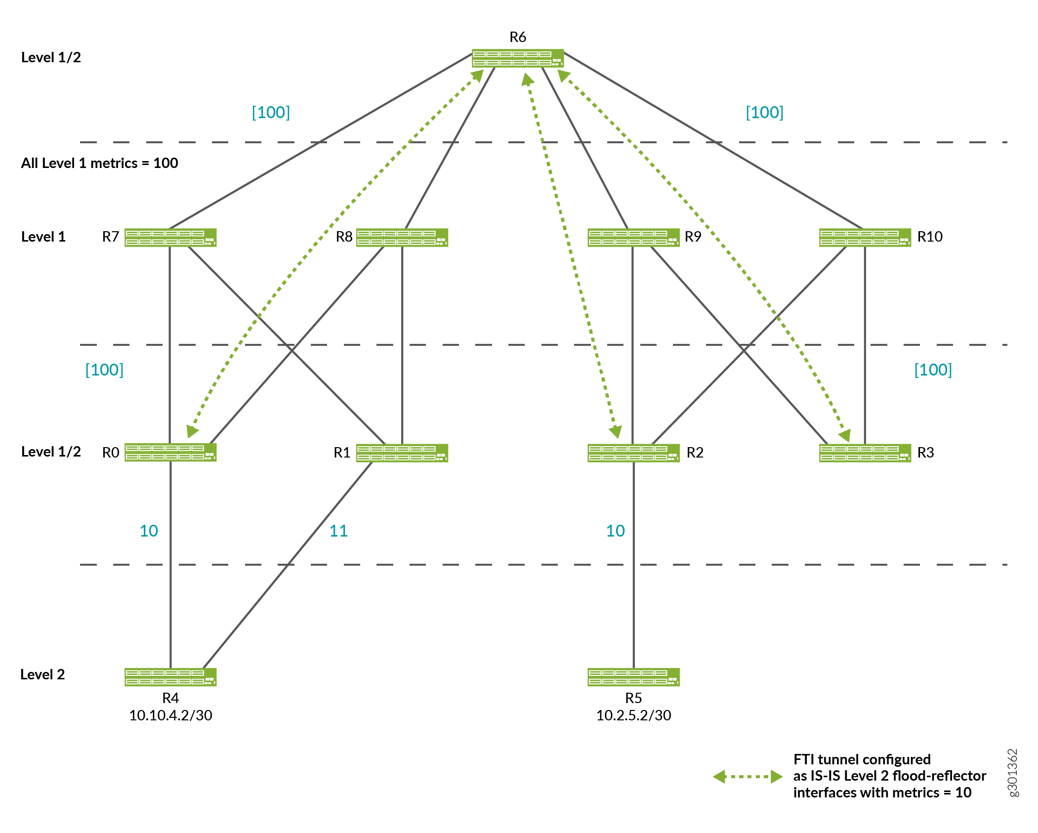
Figure 1 depicts a flood-reflector topology that allows R4 to send traffic to R5 utilizing the Level 1 fabric shown at the top of the figure without being exposed to any Level 1 advertisements.

-
R6 is the flood reflector. R0, R1, R2, R3 are flood-reflector clients and have FTI tunnels to R6. All of the FTI tunnels have metric 10 and are configured as flood-reflector interfaces. R0, R1, R2, R3, R6 are configured to redistribute Level 2 routes into Level 1 as Level 1/Level 2 inter-area routes. This redistribution into Level 1 only occurs if the Level 2 route is installed in the route table.
-
R2 advertises 10.2.5.2/30 in Level 1 link-state PDUs with a cost of 10 as it has installed the Level 2 route for 10.2.5.2/30 over the physical interface from R2 to R5.
-
Under normal circumstances, if the FTI tunnel from R3 to R6 was not configured as a flood reflector interface, then R3 would also advertise 10.2.5.2/30 into Level 1 link-state PDUs with a cost of 30.
However, as the FTI tunnel from R3 to R6 is configured as a flood reflector-interface, the Level 2 route is suppressed in favor of the Level 1 route for 10.2.5.2/30 being advertised by R3 into Level 1 link-state PDUs. The same logic applies to R0 and R1. Therefore, only R2 advertises 10.2.5.2/24 in Level 1 link-state PDUs.
-
When we trace a packet destined for 10.2.5.2/30 from R4 to R5, R4 only sees Level 2 advertisements. Therefore, it determines that the Level 2 shortest path to reach 10.2.5.2/30 is R4-R0-R6-R2-R5. R4 sends the packet to R0.
-
At R0, the shortest Level 2 path to reach 10.2.5.2/30 is R0-R6-R2-R5 (with cost 30). However, as the next hop for this Level 2 route uses a flood-reflector interface, the Level 2 route is suppressed. Instead, the Level 1 route to reach R2 is used.
-
R7, R8, R9, R10 use the Level 1 route to reach R2 as they do not participate in Level 2. R6 uses the Level 1 route because all of the Level 2 routes on R6 use FTI tunnels configured as Level 2 flood-reflector interfaces, so all Level 2 routes are suppressed at R6.
-
At R2, the Level 2 internal route for 10.2.5.2/30 using the physical Level 2 interface to R5 is installed and used.
Requirements for Configuring Flood-reflector Interfaces
The following requirements are enforced through IS-IS advertisements by including information about the role of the router (flood reflector or flood-reflector client) as well as the cluster-identifier (ID) in the IS-IS Hello messages:
-
A flood-reflector client must not be allowed to connect to another flood-reflector client over a flood-reflector interface.
-
A flood-reflector client must be allowed to connect to multiple flood reflectors over flood-reflector interfaces.
-
A flood reflector must not be allowed to connect to another flood reflector over a flood reflector-interface.
-
Adjacency between a flood reflector and a flood reflector client can be established only if they have the same cluster ID.
-
A flood reflector for a given level (Level 1, Level 2, or Level 1/Level 2) must not have any IS-IS interfaces at a given level that are not flood-reflector interfaces. This can be validated with
commit checkwithout any advertisements.
We recommend configuring the Level 2 tunnels to use the source and destination loopback addresses that are only advertised into Level 1. Different loopback addresses are advertised into Level 2. Otherwise, you might encounter a scenario where the edge router in the fabric becomes disconnected from the Level 1 fabric, but it is still able to form a flood- reflector adjacency by tunneling over links in the Level 2 topology.
Limitations
Flood reflection carries with it the potential to disrupt traffic and routing loops in certain topologies where it is not configured properly.
Routing Loops
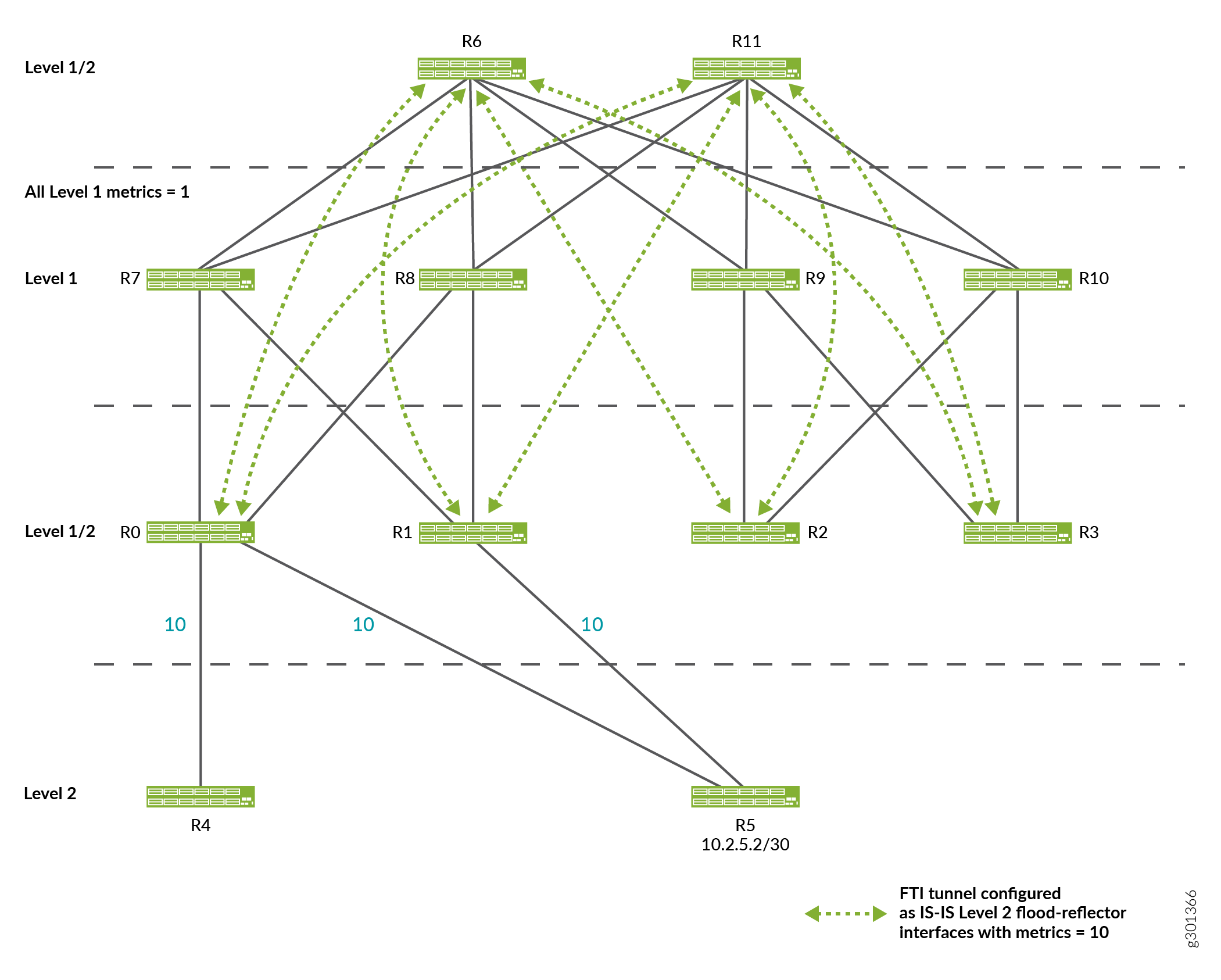
When using flood reflection, it is possible to create topologies that cause routing loops. Figure 2 depicts a looping topology sample.
The only difference between the topologies in Figure 1 and Figure 2 is the missing the FTI tunnel between R1 and R6 in Figure 2.
Other Factors that Cause Routing Loops
Besides the missing FTI tunnel described in the topology in Figure 2, the following factors can also cause a routing loop:
-
Tunnel establishment being slow or a tunnel never getting established.
-
Level 1 metrics being larger than the Level 2 metrics.
Limitations with ECMP
When using flood reflectors, it is possible to encounter some issues with ECMP resulting in minimal usage of the paths through the network. The following cases represent some issues with ECMP:
-
ECMP Expected from Level 2 SPF not Realized in Forwarding

In this topology, based on its Level 2 SPF computation, R4 expects the traffic to enter the Level 1 fabric at R0 and exit at R1 and R2, with traffic being load balanced equally across the links from R1 to R5 and R2 to R5.
However, the Level 1 cost from R0 to R1 is 2 while the Level 1 cost from R0 to R2 is 4. All of the traffic is forwarded to R1 in the Level 1 fabric and uses the link from R1 to R5.
This issue can be addressed by building a full mesh of equal-cost Level 1 tunnels between each of the Level 1/ Level 2 leaf routers.
-
ECMP Expected from Level 2 SPF not Effectively Utilized
Based on its Level 2 SPF computation, R4 expects the traffic to be sent only across the link from R0 to R5. This is the observed forwarding behavior. However, this behavior limits to utilize ECMP effectively. Building a full-mesh of equal-cost Level 1 tunnels between all of the Level 2/Level 1 leaf routers does not solve this issue.
See Also
Example: IS-IS Flood Reflector
This example shows how to configure flood reflectors in an IS-IS network. Flood reflection mainly reduces the redundancy in flooding paths and enhances the efficiency of IS-IS updates in large fabric topologies.
Requirements
This example uses the following hardware and software components:
Eleven PTX Series routers.
Junos OS Release 20.4R1 or later running on all devices.
Overview
Starting in Junos OS Release 20.4R1, you can configure flood-reflector interfaces in an IS-IS network. Flood reflection enables you to create IS-IS topologies where Level 1 areas provide transit forwarding for Level 2 destinations within a Level 2 topology. This is accomplished by creating Level 2 flood-reflection adjacencies within each Level 1 area.
A flood-reflector adjacency reflects Level 2 link-state packet data units (PDUs) and they are used in the Level 2 shortest-path-first (SPF) computation. However, they are not used for forwarding.
To establish IS-IS adjacency for flood-reflection, flexible tunnel interfaces (FTI) are designated as flood-reflector interfaces. These tunnels utilize UDP encapsulation.
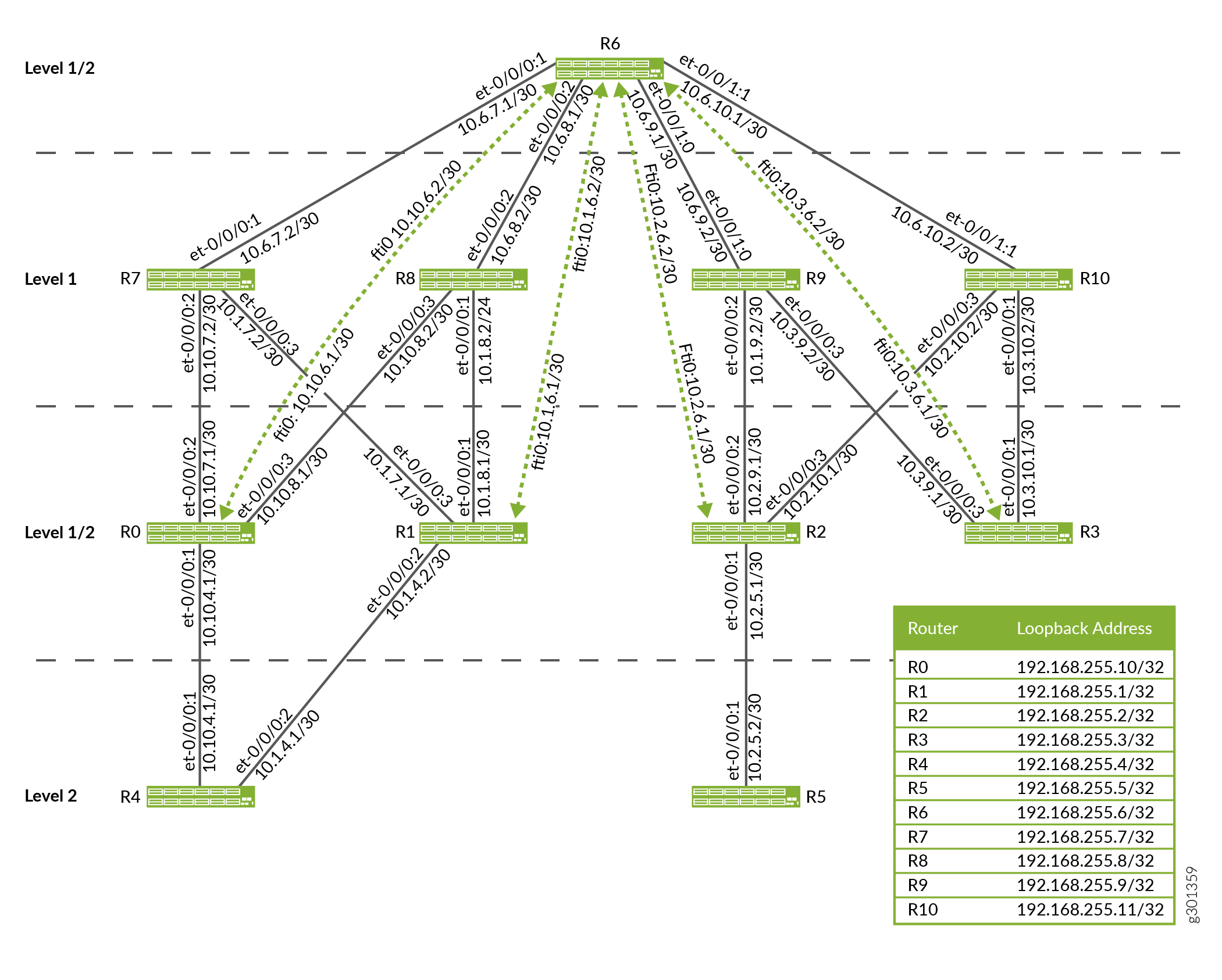
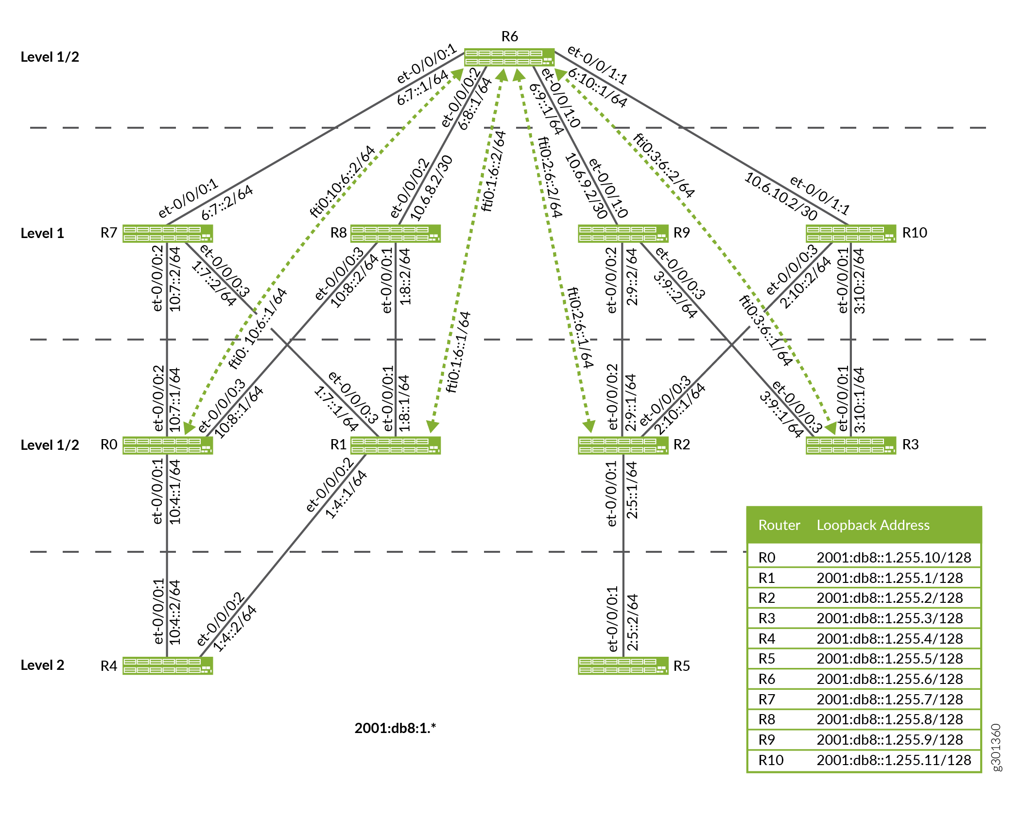
Topology
Figure 3 shows a flood-reflector topology for IPv4 traffic and Figure 4 shows a flood-reflector topology for IPv6 traffic in which Router R6 is the flood reflector. Routers R0, R1, R2, R3 are the flood-reflector clients that have FTI tunnels to R6. All of the FTI tunnels have metric 10 and are configured as flood-reflector interfaces. Routers R0, R1, R2, R3 are configured to redistribute Level 2 routes into Level 1 as Level 1/Level 2 inter-area routes. Routers R4 and R5 are Level 2 routers. Routers R7, R8, R9, R10 use the Level 1 route as they do not participate in flood reflection. The Level 1 metric is 100.
Configuration
- CLI Quick Configuration
- Configuring the Flood-Reflector Client
- Configuring the Flood Reflector
- Configuring the Non-Flood Reflector Device at Level 2
- Configuring the Non-Flood Reflector Device at Level 1
CLI Quick Configuration
To quickly configure this example, copy the
following commands, paste them into a text file, remove any line breaks,
change any details necessary to match your network configuration,
copy and paste the commands into the CLI at the [edit] hierarchy
level, and then enter commit from the configuration mode.
Device R0
set interfaces et-0/0/0:1 description R0-to-R4
set interfaces et-0/0/0:1 unit 0 family inet address 10.10.4.1/30
set interfaces et-0/0/0:1 unit 0 family iso
set interfaces et-0/0/0:1 unit 0 family inet6 address 2001:db8:1:10:4::1/64
set interfaces et-0/0/0:2 description R0-to-R7
set interfaces et-0/0/0:2 unit 0 family inet address 10.10.7.1/30
set interfaces et-0/0/0:2 unit 0 family iso
set interfaces et-0/0/0:2 unit 0 family inet6 address 2001:db8:1:10:7::1/64
set interfaces et-0/0/0:3 description R0-to-R8
set interfaces et-0/0/0:3 unit 0 family inet address 10.10.8.1/30
set interfaces et-0/0/0:3 unit 0 family iso
set interfaces et-0/0/0:3 unit 0 family inet6 address 2001:db8:1:10:8::1/64
set interfaces lo0 unit 0 family inet address 192.168.255.10/32 primary
set interfaces lo0 unit 0 family iso address 49.0001.1921.6825.5010.00
set interfaces lo0 unit 0 family inet6 address 2001:db8:1:255::10/128
set routing-options router-id 192.168.255.10
set interfaces fti0 unit 0 tunnel encapsulation udp source address 192.168.255.10
set interfaces fti0 unit 0 tunnel encapsulation udp destination address 192.168.255.6
set interfaces fti0 unit 0 family inet address 10.10.6.1/30
set interfaces fti0 unit 0 family inet destination-udp-port 10000
set interfaces fti0 unit 0 family iso destination-udp-port 10030
set interfaces fti0 unit 0 family inet6 destination-udp-port 10010
set interfaces fti0 unit 0 family mpls destination-udp-port 10020
set protocols isis interface et-0/0/0:1.0 level 1 disable
set protocols isis interface et-0/0/0:1.0 level 2 metric 10
set protocols isis interface et-0/0/0:1.0 point-to-point
set protocols isis interface et-0/0/0:2.0 level 2 disable
set protocols isis interface et-0/0/0:2.0 level 1 metric 100
set protocols isis interface et-0/0/0:2.0 point-to-point
set protocols isis interface et-0/0/0:3.0 level 2 disable
set protocols isis interface et-0/0/0:3.0 level 1 metric 100
set protocols isis interface et-0/0/0:3.0 point-to-point
set protocols isis interface fti0.0 level 1 disable
set protocols isis interface fti0.0 level 2 flood-reflector cluster-id 100
set protocols isis interface lo0.0 passive
set protocols isis level 1 wide-metrics-only
set protocols isis level 2 wide-metrics-only
set protocols isis level 2 flood-reflector client
set protocols isis export l2_l1_leak
Device R1
set interfaces et-0/0/0:1 description R1-to-R8
set interfaces et-0/0/0:1 unit 0 family inet address 10.1.8.1/30
set interfaces et-0/0/0:1 unit 0 family iso
set interfaces et-0/0/0:1 unit 0 family inet6 address 2001:db8:1:1:7::1/64
set interfaces et-0/0/0:2 description R1-to-R4
set interfaces et-0/0/0:2 unit 0 family inet address 10.1.4.1/30
set interfaces et-0/0/0:2 unit 0 family iso
set interfaces et-0/0/0:2 unit 0 family inet6 address 2001:db8:1:1:8::1/64
set interfaces et-0/0/0:3 description R1-to-R7
set interfaces et-0/0/0:3 unit 0 family inet address 10.1.7.1/30
set interfaces et-0/0/0:3 unit 0 family iso
set interfaces et-0/0/0:3 unit 0 family inet6 address 2001:db8:1:1:4::1/64
set interfaces lo0 unit 0 family inet address 192.168.255.1/32 primary
set interfaces lo0 unit 0 family iso address 49.0001.1921.6825.5001.00
set interfaces lo0 unit 0 family inet6 address 2001:db8:1:255::1/128
set routing-options router-id 192.168.255.1
set interfaces fti0 unit 0 tunnel encapsulation udp source address 192.168.255.1
set interfaces fti0 unit 0 tunnel encapsulation udp destination address 192.168.255.6
set interfaces fti0 unit 0 family inet address 10.1.6.1/30
set interfaces fti0 unit 0 family inet destination-udp-port 10000
set interfaces fti0 unit 0 family iso destination-udp-port 10030
set interfaces fti0 unit 0 family inet6 destination-udp-port 10010
set interfaces fti0 unit 0 family mpls destination-udp-port 10020
set protocols isis interface et-0/0/0:1.0 level 2 disable
set protocols isis interface et-0/0/0:1.0 level 1 metric 100
set protocols isis interface et-0/0/0:1.0 point-to-point
set protocols isis interface et-0/0/0:2.0 level 1 disable
set protocols isis interface et-0/0/0:2.0 level 2 metric 11
set protocols isis interface et-0/0/0:2.0 point-to-point
set protocols isis interface et-0/0/0:3.0 level 2 disable
set protocols isis interface et-0/0/0:3.0 level 1 metric 100
set protocols isis interface et-0/0/0:3.0 point-to-point
set protocols isis interface fti0.0 level 1 disable
set protocols isis interface fti0.0 level 2 flood-reflector cluster-id 100
set protocols isis interface lo0.0 passive
set protocols isis level 2 wide-metrics-only
set protocols isis level 2 flood-reflector client
set protocols isis level 1 wide-metrics-only
set protocols isis export l2_l1_leak
Device R2
set interfaces et-0/0/0:1 description R2-to-R5
set interfaces et-0/0/0:1 unit 0 family inet address 10.2.5.1/30
set interfaces et-0/0/0:1 unit 0 family iso
set interfaces et-0/0/0:1 unit 0 family inet6 address 2001:db8:1:2:5::1/64
set interfaces et-0/0/0:2 description R2-to-R9
set interfaces et-0/0/0:2 unit 0 family inet address 10.2.9.1/30
set interfaces et-0/0/0:2 unit 0 family iso
set interfaces et-0/0/0:2 unit 0 family inet6 address 2001:db8:1:2:9::1/64
set interfaces et-0/0/0:3 description R2-to-R10
set interfaces et-0/0/0:3 unit 0 family inet address 10.2.10.1/30
set interfaces et-0/0/0:3 unit 0 family iso
set interfaces et-0/0/0:3 unit 0 family inet6 address 2001:db8:1:2:10::1/64
set interfaces lo0 unit 0 family inet address 192.168.255.2/32 primary
set interfaces lo0 unit 0 family iso address 49.0001.1921.6825.5002.00
set interfaces lo0 unit 0 family inet6 address 2001:db8:1:255::2/128
set routing-options router-id 192.168.255.2
set interfaces fti0 unit 0 tunnel encapsulation udp source address 192.168.255.2
set interfaces fti0 unit 0 tunnel encapsulation udp destination address 192.168.255.6
set interfaces fti0 unit 0 family inet address 10.2.6.1/30
set interfaces fti0 unit 0 family inet destination-udp-port 10000
set interfaces fti0 unit 0 family iso destination-udp-port 10030
set interfaces fti0 unit 0 family inet6 destination-udp-port 10010
set interfaces fti0 unit 0 family mpls destination-udp-port 10020
set protocols isis interface et-0/0/0:1.0 level 1 disable
set protocols isis interface et-0/0/0:1.0 level 2 metric 10
set protocols isis interface et-0/0/0:1.0 point-to-point
set protocols isis interface et-0/0/0:2.0 level 2 disable
set protocols isis interface et-0/0/0:2.0 level 1 metric 100
set protocols isis interface et-0/0/0:2.0 point-to-point
set protocols isis interface et-0/0/0:3.0 level 2 disable
set protocols isis interface et-0/0/0:3.0 level 1 metric 100
set protocols isis interface et-0/0/0:3.0 point-to-point
set protocols isis interface fti0.0 level 1 disable
set protocols isis interface fti0.0 level 2 flood-reflector cluster-id 100
set protocols isis interface lo0.0 passive
set protocols isis level 1 wide-metrics-only
set protocols isis level 2 wide-metrics-only
set protocols isis level 2 flood-reflector client
set protocols isis export l2_l1_leak
Device R3
set interfaces et-0/0/0:1 description R3-to-R10
set interfaces et-0/0/0:1 unit 0 family inet address 10.3.10.1/30
set interfaces et-0/0/0:1 unit 0 family iso
set interfaces et-0/0/0:1 unit 0 family inet6 address 2001:db8:1:3:10::1/64
set interfaces et-0/0/0:3 description R3-to-R9
set interfaces et-0/0/0:3 unit 0 family inet address 10.3.9.1/30
set interfaces et-0/0/0:3 unit 0 family iso
set interfaces et-0/0/0:3 unit 0 family inet6 address 2001:db8:1:3:9::1/64
set interfaces fti0 unit 0 tunnel encapsulation udp source address 192.168.255.3
set interfaces fti0 unit 0 tunnel encapsulation udp destination address 192.168.255.6
set interfaces fti0 unit 0 family inet address 10.3.6.1/30
set interfaces fti0 unit 0 family inet destination-udp-port 10000
set interfaces fti0 unit 0 family iso destination-udp-port 10030
set interfaces fti0 unit 0 family inet6 destination-udp-port 10010
set interfaces fti0 unit 0 family mpls destination-udp-port 10020
set interfaces lo0 unit 0 family inet address 192.168.255.3/32 primary
set interfaces lo0 unit 0 family iso address 49.0001.1921.6825.5003.00
set interfaces lo0 unit 0 family inet6 address 2001:db8:1:255::3/128
set routing-options router-id 192.168.255.3
set protocols isis interface et-0/0/0:1.0 level 2 disable
set protocols isis interface et-0/0/0:1.0 level 1 metric 100
set protocols isis interface et-0/0/0:1.0 point-to-point
set protocols isis interface et-0/0/0:3.0 level 2 disable
set protocols isis interface et-0/0/0:3.0 level 1 metric 100
set protocols isis interface et-0/0/0:3.0 point-to-point
set protocols isis interface fti0.0 level 1 disable
set protocols isis interface fti0.0 level 2 flood-reflector cluster-id 100
set protocols isis interface lo0.0 passive
set protocols isis level 1 wide-metrics-only
set protocols isis level 2 wide-metrics-only
set protocols isis level 2 flood-reflector client
set protocols isis export l2_l1_leak
Device R4
set interfaces et-0/0/0:1 description R4-to-R0
set interfaces et-0/0/0:1 unit 0 family inet address 10.10.4.2/30
set interfaces et-0/0/0:1 unit 0 family iso
 set interfaces et-0/0/0:1 unit 0 family inet6 address 2001:db8:1:10:4::2/64
set interfaces et-0/0/0:2 description R4-to-R1
set interfaces et-0/0/0:2 unit 0 family inet address 10.1.4.2/30
set interfaces et-0/0/0:2 unit 0 family iso
set interfaces et-0/0/0:2 unit 0 family inet6 address 2001:db8:1:1:4::2/64
set interfaces lo0 unit 0 family inet address 192.168.255.4/32 primary
set interfaces lo0 unit 0 family iso address 49.0001.1921.6825.5004.00
set interfaces lo0 unit 0 family inet6 address 2001:db8:1:255::4/128
set routing-options router-id 192.168.255.4
set protocols isis interface et-0/0/0:1.0 level 1 disable
set protocols isis interface et-0/0/0:1.0 level 2 metric 10
set protocols isis interface et-0/0/0:1.0 point-to-point
set protocols isis interface et-0/0/0:2.0 level 1 disable
set protocols isis interface et-0/0/0:2.0 level 2 metric 11
set protocols isis interface et-0/0/0:2.0 point-to-point
set protocols isis interface lo0.0 passive
set protocols isis level 1 wide-metrics-only
set protocols isis level 2 wide-metrics-only
Device R5
set interfaces et-0/0/0:1 description R5-to-R2
set interfaces et-0/0/0:1 unit 0 family inet address 10.2.5.2/30
set interfaces et-0/0/0:1 unit 0 family iso
set interfaces et-0/0/0:1 unit 0 family inet6 address 2001:db8:1:2:5::2/64
set interfaces lo0 unit 0 family inet address 192.168.255.5/30 primary
set interfaces lo0 unit 0 family iso address 49.0001.1921.6825.5005.00
set interfaces lo0 unit 0 family inet6 address 2001:db8:1:255::5/128
set routing-options router-id 192.168.255.5
set protocols isis interface et-0/0/0:1.0 level 1 disable
set protocols isis interface et-0/0/0:1.0 level 2 metric 10
set protocols isis interface et-0/0/0:1.0 point-to-point
set protocols isis interface lo0.0 passive
set protocols isis level 1 wide-metrics-only
set protocols isis level 2 wide-metrics-only
Device R6
set interfaces et-0/0/0:1 description R6-to-R7
set interfaces et-0/0/0:1 unit 0 family inet address 10.6.7.1/30
set interfaces et-0/0/0:1 unit 0 family iso
set interfaces et-0/0/0:1 unit 0 family inet6 address 2001:db8:1:6:7::1/64
set interfaces et-0/0/0:2 description R6-to-R8
set interfaces et-0/0/0:2 unit 0 family inet address 10.6.8.1/30
set interfaces et-0/0/0:2 unit 0 family iso
set interfaces et-0/0/0:2 unit 0 family inet6 address 2001:db8:1:6:8::1/64
set interfaces et-0/0/1:0 description R6-to-R9-Link
set interfaces et-0/0/1:0 unit 0 family inet address 10.6.9.1/30
set interfaces et-0/0/1:0 unit 0 family iso
set interfaces et-0/0/1:0 unit 0 family inet6 address 2001:db8:1:6:9::1/64
set interfaces et-0/0/1:1 description R6-to-R10
set interfaces et-0/0/1:1 unit 0 family inet address 10.6.10.1/30
set interfaces et-0/0/1:1 unit 0 family iso
set interfaces et-0/0/1:1 unit 0 family inet6 address 2001:db8:1:6:10::1/64
set interfaces lo0 unit 0 family inet address 192.168.255.6/32 primary
set interfaces lo0 unit 0 family iso address 49.0001.1921.6825.5006.00
set interfaces lo0 unit 0 family inet6 address 2001:db8:1:255::6/128
set routing-options router-id 192.168.255.6
set interfaces fti0 unit 0 tunnel encapsulation udp source address 192.168.255.6
set interfaces fti0 unit 0 tunnel encapsulation udp destination address 192.168.255.10
set interfaces fti0 unit 0 family inet address 10.10.6.2/30
set interfaces fti0 unit 0 family inet destination-udp-port 10000
set interfaces fti0 unit 0 family iso destination-udp-port 10030
set interfaces fti0 unit 0 family inet6 destination-udp-port 10010
set interfaces fti0 unit 0 family mpls destination-udp-port 10020
set interfaces fti0 unit 1 tunnel encapsulation udp source address 192.168.255.6
set interfaces fti0 unit 1 tunnel encapsulation udp destination address 192.168.255.1
set interfaces fti0 unit 1 family inet address 10.1.6.2/30
set interfaces fti0 unit 1 family inet destination-udp-port 10000
set interfaces fti0 unit 1 family iso destination-udp-port 10030
set interfaces fti0 unit 1 family inet6 destination-udp-port 10010
set interfaces fti0 unit 1 family mpls destination-udp-port 10020
set interfaces fti0 unit 2 tunnel encapsulation udp source address 192.168.255.6
set interfaces fti0 unit 2 tunnel encapsulation udp destination address 192.168.255.2
set interfaces fti0 unit 2 family inet address 10.2.6.2/30
set interfaces fti0 unit 2 family inet destination-udp-port 10000
set interfaces fti0 unit 2 family iso destination-udp-port 10030
set interfaces fti0 unit 2 family inet6 destination-udp-port 10010
set interfaces fti0 unit 2 family mpls destination-udp-port 10020
set interfaces fti0 unit 3 tunnel encapsulation udp source address 192.168.255.6
set interfaces fti0 unit 3 tunnel encapsulation udp destination address 192.168.255.3
set interfaces fti0 unit 3 family inet address 10.3.6.2/30
set interfaces fti0 unit 3 family inet destination-udp-port 10000
set interfaces fti0 unit 3 family iso destination-udp-port 10030
set interfaces fti0 unit 3 family inet6 destination-udp-port 10010
set interfaces fti0 unit 3 family mpls destination-udp-port 10020
set protocols isis interface et-0/0/0:1.0 level 2 disable
set protocols isis interface et-0/0/0:2.0 level 1 metric 100
set protocols isis interface et-0/0/0:2.0 level 2 disable
set protocols isis interface et-0/0/0:2.0 point-to-point
set protocols isis interface et-0/0/1:0.0 level 2 disable
set protocols isis interface et-0/0/1:0.0 level 1 metric 100
set protocols isis interface et-0/0/1:0.0 point-to-point
set protocols isis interface et-0/0/1:1.0 level 2 disable
set protocols isis interface et-0/0/1:1.0 level 1 metric 100
set protocols isis interface et-0/0/1:1.0 point-to-point
set protocols isis interface fti0.0 level 1 disable
set protocols isis interface fti0.0 level 2 flood-reflector
set protocols isis interface fti0.1 level 1 disable
set protocols isis interface fti0.1 level 2 flood-reflector
set protocols isis interface fti0.2 level 1 disable
set protocols isis interface fti0.2 level 2 flood-reflector
set protocols isis interface fti0.3 level 1 disable
set protocols isis interface fti0.3 level 2 flood-reflector
set protocols isis interface lo0.0 level 2 disable
set protocols isis interface lo0.0 point-to-point
set protocols isis interface lo0.0 passive
set protocols isis level 1 wide-metrics-only
set protocols isis level 2 wide-metrics-only
set protocols isis level 2 flood-reflector reflector cluster-id 100
set protocols isis export l2_l1_leak
Device R7
set interfaces et-0/0/0:1 description R7-to-R6
set interfaces et-0/0/0:1 unit 0 family inet address 10.6.7.2/30
set interfaces et-0/0/0:1 unit 0 family iso
set interfaces et-0/0/0:1 unit 0 family inet6 address 2001:db8:1:6:7::2/64
set interfaces et-0/0/0:2 description R7-to-R0
set interfaces et-0/0/0:2 unit 0 family inet address 10.10.7.2/30
set interfaces et-0/0/0:2 unit 0 family iso
set interfaces et-0/0/0:2 unit 0 family inet6 address 2001:db8:1:10:7::2/64
set interfaces et-0/0/0:3 description R7-to-R1
set interfaces et-0/0/0:3 unit 0 family inet address 10.1.7.2/30
set interfaces et-0/0/0:3 unit 0 family iso
set interfaces et-0/0/0:3 unit 0 family inet6 address 2001:db8:1:1:7::2/64
set interfaces lo0 unit 0 family inet address 192.168.255.7/32 primary
set interfaces lo0 unit 0 family iso address 49.0001.1921.6825.5007.00
set interfaces lo0 unit 0 family inet6 address 2001:db8:1:255::7/128
set routing-options router-id 192.168.255.7
set protocols isis interface et-0/0/0:1.0 level 2 disable
set protocols isis interface et-0/0/0:1.0 level 1 metric 100
set protocols isis interface et-0/0/0:1.0 point-to-point
set protocols isis interface et-0/0/0:2.0 level 2 disable
set protocols isis interface et-0/0/0:2.0 level 1 metric 100
set protocols isis interface et-0/0/0:2.0 point-to-point
set protocols isis interface et-0/0/0:3.0 level 2 disable
set protocols isis interface et-0/0/0:3.0 level 1 metric 100
set protocols isis interface et-0/0/0:3.0 point-to-point
set protocols isis interface lo0.0 passive
set protocols isis level 1 wide-metrics-only
set protocols isis level 2 wide-metrics-only
Device R8
set interfaces et-0/0/0:1 description R8-to-R1
set interfaces et-0/0/0:1 unit 0 family inet address 10.1.8.2/30
set interfaces et-0/0/0:1 unit 0 family iso
set interfaces et-0/0/0:1 unit 0 family inet6 address 2001:db8:1:1:8::2/64
set interfaces et-0/0/0:2 description R8-to-R6
set interfaces et-0/0/0:2 unit 0 family inet address 10.6.8.2/30
set interfaces et-0/0/0:2 unit 0 family iso
set interfaces et-0/0/0:2 unit 0 family inet6 address 2001:db8:1:6:8::2/64
set interfaces et-0/0/0:3 description R8-to-R0
set interfaces et-0/0/0:3 unit 0 family inet address 10.10.8.2/30
set interfaces et-0/0/0:3 unit 0 family iso
set interfaces et-0/0/0:3 unit 0 family inet6 address 2001:db8:1:10:8::2/64
set interfaces lo0 unit 0 family inet address 192.168.255.11/32 primary
set interfaces lo0 unit 0 family inet address 192.168.255.8/32 primary
set interfaces lo0 unit 0 family inet6 address 2001:db8:1:255::8/128
set interfaces lo0 unit 0 family iso address 49.0001.1921.6825.5008.00
set routing-options router-id 192.168.255.11
set protocols isis interface et-0/0/0:1.0 level 2 disable
set protocols isis interface et-0/0/0:1.0 level 1 metric 100
set protocols isis interface et-0/0/0:1.0 point-to-point
set protocols isis interface et-0/0/0:2.0 level 2 disable
set protocols isis interface et-0/0/0:2.0 level 1 metric 100
set protocols isis interface et-0/0/0:2.0 point-to-point
set protocols isis interface et-0/0/0:3.0 level 2 disable
set protocols isis interface et-0/0/0:3.0 level 1 metric 100
set protocols isis interface et-0/0/0:3.0 point-to-point
set protocols isis interface lo0.0 passive
set protocols isis level 1 wide-metrics-only
set protocols isis level 2 wide-metrics-only
Device R9
set interfaces et-0/0/0:2 description R9-to-R2
set interfaces et-0/0/0:2 unit 0 family inet address 10.2.9.2/30
set interfaces et-0/0/0:2 unit 0 family iso
set interfaces et-0/0/0:2 unit 0 family inet6 address 2001:db8:1:2:9::2/64
set interfaces et-0/0/0:3 description R9-to-R3
set interfaces et-0/0/0:3 unit 0 family inet address 10.3.9.2/30
set interfaces et-0/0/0:3 unit 0 family iso
set interfaces et-0/0/0:3 unit 0 family inet6 address 2001:db8:1:3:9::2/64
set interfaces et-0/0/1:0 description R9-to-R6
set interfaces et-0/0/1:0 unit 0 family inet address 10.6.9.2/30
set interfaces et-0/0/1:0 unit 0 family iso
set interfaces et-0/0/1:0 unit 0 family inet6 address 2001:db8:1:6:9::2/64
set interfaces lo0 unit 0 family inet address 192.168.255.9/32 primary
set interfaces lo0 unit 0 family inet6 address 2001:db8:1:255::9/128
set interfaces lo0 unit 0 family iso address 49.0001.1921.6825.5009.00
set routing-options router-id 192.168.255.9
set protocols isis interface et-0/0/0:2.0 level 2 disable
set protocols isis interface et-0/0/0:2.0 level 1 metric 100
set protocols isis interface et-0/0/0:2.0 point-to-point
set protocols isis interface et-0/0/0:3.0 level 2 disable
set protocols isis interface et-0/0/0:3.0 level 1 metric 100
set protocols isis interface et-0/0/0:3.0 point-to-point
set protocols isis interface et-0/0/1:0.0 level 2 disable
set protocols isis interface et-0/0/1:0.0 level 1 metric 100
set protocols isis interface et-0/0/1:0.0 point-to-point
set protocols isis interface lo0.0 passive
set protocols isis level 1 wide-metrics-only
set protocols isis level 2 wide-metrics-only
Device R10
set interfaces et-0/0/0:1 description R10-to-R3
set interfaces et-0/0/0:1 unit 0 family inet address 10.3.10.2/30
set interfaces et-0/0/0:1 unit 0 family iso
set interfaces et-0/0/0:1 unit 0 family inet6 address 2001:db8:1:3:10::2/64
set interfaces et-0/0/0:3 description R10-to-R2
set interfaces et-0/0/0:3 unit 0 family inet address 10.2.10.2/30
set interfaces et-0/0/0:3 unit 0 family iso
set interfaces et-0/0/0:3 unit 0 family inet6 address 2001:db8:1:2:10::2/64
set interfaces et-0/0/1:1 description R10-to-R6
set interfaces et-0/0/1:1 unit 0 family inet address 10.6.10.2/30
set interfaces et-0/0/1:1 unit 0 family iso
set interfaces et-0/0/1:1 unit 0 family inet6 address 2001:db8:1:6:10::2/64
set interfaces lo0 unit 0 family inet address 192.168.255.11/32 primary
set interfaces lo0 unit 0 family inet6 address 2001:db8:1:255::11/128
set interfaces lo0 unit 0 family iso address 49.0001.1921.6825.5011.00
set routing-options router-id 192.168.255.11
set protocols isis interface et-0/0/0:1.0 level 2 disable
set protocols isis interface et-0/0/0:1.0 level 1 metric 100
set protocols isis interface et-0/0/0:1.0 point-to-point
set protocols isis interface et-0/0/0:3.0 level 2 disable
set protocols isis interface et-0/0/0:3.0 level 1 metric 100
set protocols isis interface et-0/0/0:3.0 point-to-point
set protocols isis interface et-0/0/1:1.0 level 2 disable
set protocols isis interface et-0/0/1:1.0 level 1 metric 100
set protocols isis interface et-0/0/1:1.0 point-to-point
set protocols isis interface lo0.0 passive
set protocols isis level 1 wide-metrics-only
set protocols isis level 2 wide-metrics-only
Configuring the Flood-Reflector Client
Step-by-Step Procedure
To configure the flood-reflector client R0, perform these tasks:
Configure the device interfaces to enable IP and ISO transport.
[edit]
user@R0#set interfaces et-0/0/0:1 unit 0 description "Connection Between R_0 and R_4"
user@R0#set interfaces et-0/0/0:1 unit 0 family inet address 10.10.4.1/30
user@R0#set interfaces et-0/0/0:1 unit 0 family iso
user@R0#set interfaces et-0/0/0:1 unit 0 family inet6 address 2001:db8:1:10:4::1/64
user@R0#set interfaces et-0/0/0:2 unit 0 description "Connection Between R_0 and R_7"
user@R0#set interfaces et-0/0/0:2 unit 0 family inet address 10.10.7.1/30
user@R0#set interfaces et-0/0/0:2 unit 0 family iso
user@R0#set interfaces et-0/0/0:2 unit 0 family inet6 address 2001:db8:1:10:7::1/64
user@R0#set interfaces et-0/0/0:3 unit 0 description "Connection Between R_0 and R_8"
user@R0#set interfaces et-0/0/0:3 unit 0 family inet address 10.10.8.1/30
user@R0#set interfaces et-0/0/0:3 unit 0 family iso
user@R0#set interfaces et-0/0/0:3 unit 0 family inet6 address 2001:db8:1:10:8::1/64
Configure the loopback interface (lo0) with IPv4 and IPv6 addresses that are used as router ID for IS-IS sessions. Configure an ISO network entity title (NET) address on the loopback interface for the router to support IS-IS.
[edit]
user@R0#set interfaces lo0 unit 0 family inet address 192.168.255.10/32 primary
user@R0#set interfaces lo0 unit 0 family iso address 49.0001.1921.6825.5010.00
user@R0#set interfaces lo0 unit 0 family inet6 address 2001:db8:1:255::10/128
Configure routing options to identify the router in the domain.
[edit]
user@R0#set routing-options router-id 192.168.255.10
Configure the source address for the FTI with UDP encapsulation. The source address is the router ID of the tunnel source.
[edit]
user@R0#set interfaces fti0 unit 0 tunnel encapsulation udp source address 192.168.255.10
Configure the destination address for the FTI. The destination address is the router ID of the tunnel endpoint.
[edit]
user@R0#set interfaces fti0 unit 0 tunnel encapsulation udp destination address 192.168.255.6
Specify the source IP address of the tunnel and the UDP port value of the destination that identifies the tunnel endpoint. Specify the value of
destination-udp-portfrom 1 through 65,535.[edit] user@R0#set interfaces fti0 unit 0 family inet address 10.10.6.1/30 user@R0#set interfaces fti0 unit 0 family inet destination-udp-port 10000 user@R0#set interfaces fti0 unit 0 family iso destination-udp-port 10030 user@R0#set interfaces fti0 unit 0 family inet6 destination-udp-port 10010 user@R0#set interfaces fti0 unit 0 family mpls destination-udp-port 10020
-
Disable IS-IS Level 1 on the interface that connects to an interface of R4 at Level 2. Configure a metric of 10 for the Level 2 interface.
[edit]
user@R0#set protocols isis interface et-0/0/0:1.0 level 1 disable
user@R0#set protocols isis interface et-0/0/0:1.0 level 2 metric 10
-
Disable IS-IS Level 2 on the interface that connects to interfaces of R7 and R8 at Level 1. Configure a metric of 100 for the Level 1 interfaces.
[edit]
user@R0#set protocols isis interface et-0/0/0:2.0 level 1 metric 100
user@R0#set protocols isis interface et-0/0/0:2.0 level 2 disable
user@R0#set protocols isis interface et-0/0/0:3.0 level 1 metric 100
user@R0#set protocols isis interface et-0/0/0:3.0 level 2 disable
Configure the IS-IS interfaces to behave like point-to-point interfaces.
[edit]
user@R0#set protocols isis interface et-0/0/0:1.0 point-to-point
user@R0#set protocols isis interface et-0/0/0:2.0 point-to-point
user@R0#set protocols isis interface et-0/0/0:3.0 point-to-point
Disable Level 1 on the FTI and configure the flood reflector client at Level 2 by including the cluster identifier.
[edit]
user@R0#set protocols isis interface fti0.0 level 1 disable
user@R0#set protocols isis interface fti0.0 level 2 flood-reflector cluster-id 100
user@R0#set protocols isis level 2 flood-reflector client
Configure
wide-metricsfor IS-IS to allow wider range of metric values.[edit] user@R0#set protocols isis level 1 wide-metrics-only user@R0#set protocols isis level 2 wide-metrics-only
Configure the loopback interface as passive to ensure the protocols do not run over the loopback interface and that the loopback interface is advertised correctly throughout the network.
[edit]
user@R0#set protocols isis interface lo0.0 passive
Enter commit from the configure mode on R0 device.
In addition to configuring these steps on flood-reflector client R0, repeat these steps for the flood-reflector clients R1, R2, R3 within the cluster that you configure.
Results
From configuration mode, confirm your configuration
by entering the, show interfaces, show routing-options, show protocols, and show policy-options commands.
If the output does not display the intended configuration, repeat
the instructions in this example to correct the configuration.
interfaces {
    et-0/0/0:1 {
        unit 0 {
            family inet {
                address 10.10.4.1/30;
            }
            family iso;
            family inet6 {
                address 2001:db8:1:10:4::1/64;
            }
        }
    }
    et-0/0/0:2 {
        unit 0 {
            family inet {
                address 10.10.7.1/30;
            }
            family iso;
            family inet6 {
                address 2001:db8:1:10:7::1/64;
            }
        }
    }
    et-0/0/0:3 {
        unit 0 {
            family inet {
                address 10.10.8.1/30;
            }
            family iso;
            family inet6 {
                address 2001:db8:1:10:8::1/64;
            }
        }
    }
    fti0 {
        unit 0 {
            tunnel {
                encapsulation udp {
                    source {
                        address 192.168.255.10;
                    }
                        destination  {
                            address 192.168.255.6;
                            }
                        }
            }
            family inet {
            address 10.10.6.1/30;
                destination-udp-port 10000;
            }
                family iso {
                    destination-udp-port 10030;
                }
                family inet6  {
                    destination-udp-port 10010;
                }
                family mpls  {
                    destination-udp-port 10020;
                }
        }
    }
    lo0 {
        unit 0 {
            family inet {
                address 192.168.255.10/32;
            }
            family iso {
            address 49.0001.1921.6825.5010.00;
            }
            family inet6 {
                address 2001:db8:1:255::10/128;
            }
        }
    }
}
routing-options {
    router-id 192.168.255.10;
}
protocols {
    isis {
        interface et-0/0/0:1.0 {
            level 1 disable;
            level 2 {
                metric 10;
            }
            point-to-point;
        }
        interface et-0/0/0:2.0 {
            level 2 disable;
            level 1 {
                metric 100;
            }
            point-to-point;
        }
        interface et-0/0/0:3.0;
            level 2 disable;
            level 1 {
                metric 100;
            }
            point-to-point;
        }
        interface fti0.0 {
            level 1 disable;
            level 2 {
                flood-reflector {
                cluster-id 100;
            }
        }
    }
    interface lo0.0 {
    passive;
}
level 1 wide-metrics-only;
level 2 {
     wide-metrics-only;
         flood-reflector {
        client;
    }
}
 export [ l2_l1_leak ];
Configuring the Flood Reflector
Step-by-Step Procedure
To configure the flood-reflector device R6, perform these tasks:
Configure the device interfaces to enable IP and ISO transport.
[edit]
user@R6#set interfaces et-0/0/0:1 unit 0 description "Connection Between R_6 and R_7"
user@R6#set interfaces et-0/0/0:1 unit 0 family inet address 10.6.7.1/30
user@R6#set interfaces et-0/0/0:1 unit 0 family iso
user@R6#set interfaces et-0/0/0:1 unit 0 family inet6 address 2001:db8:1:6:7::1/64
user@R6#set interfaces et-0/0/0:2 unit 0 description "Connection Between R_6 and R_8"
user@R6#set interfaces et-0/0/0:2 unit 0 family inet address 10.6.8.1/30
user@R6#set interfaces et-0/0/0:2 unit 0 family iso
user@R6#set interfaces et-0/0/0:2 unit 0 family inet6 address 2001:db8:1:6:8::1/64
user@R6#set interfaces et-0/0/0:3 unit 0 description "Connection Between R_6 and R_9"
user@R6#set interfaces et-0/0/0:3 unit 0 family inet address 10.6.9.1/30
user@R6#set interfaces et-0/0/0:3 unit 0 family iso
user@R6#set interfaces et-0/0/0:3 unit 0 family inet6 address 2001:db8:1:6:9::1/64
user@R6#set interfaces et-0/0/1:1 unit 0 description "Connection Between R_6 and R_10"
user@R6#set interfaces et-0/0/1:1 unit 0 family inet address 10.6.10.1/30
user@R6#set interfaces et-0/0/1:1 unit 0 family iso
user@R6#set interfaces et-0/0/1:1 unit 0 family inet6 address 2001:db8:1:6:10::1/64
Configure the loopback interface (lo0) with IPv4 and IPv6 addresses that are used as router ID for IS-IS sessions. Configure an ISO network entity title (NET) address on the loopback interface for the router to support IS-IS.
[edit]
user@R6#set interfaces lo0 unit 0 family inet address 192.168.255.6/32 primary
user@R6#set interfaces lo0 unit 0 family iso address 49.0001.1921.6825.5006.00
user@R6#set interfaces lo0 unit 0 family inet6 address 2001:db8:1:255::6/128
Configure routing options to identify the router in the domain.
[edit]
user@R6#set routing-options router-id 192.168.255.6
Configure the source address for the FTI with UDP encapsulation. The source address is the router ID of the tunnel source.
[edit]
user@R6#set interfaces fti0 unit 0 tunnel encapsulation udp source address 192.168.255.6
Configure the destination addresses for the FTI per unit. The destination addresses are the router IDs of the tunnel endpoints.
[edit]
user@R6#set interfaces fti0 unit 0 tunnel encapsulation udp destination address 192.168.255.10
user@R6#set interfaces fti0 unit 1 tunnel encapsulation udp destination address 192.168.255.1
user@R6#set interfaces fti0 unit 2 tunnel encapsulation udp destination address 192.168.255.2
user@R6#set interfaces fti0 unit 3 tunnel encapsulation udp destination address 192.168.255.3
Specify the source IP address of the tunnel and the UDP port value of the destination that identifies the tunnel endpoint per unit. Specify the value of
destination-udp-portfrom 1 through 65,535.[edit] user@R6#set interfaces fti0 unit 0 family inet address 10.10.6.2/30 user@R6#set interfaces fti0 unit 0 family inet destination-udp-port 10000 user@R6#set interfaces fti0 unit 0 family iso destination-udp-port 10030 user@R6#set interfaces fti0 unit 0 family inet6 destination-udp-port 10010 user@R6#set interfaces fti0 unit 0 family mpls destination-udp-port 10020 user@R6#set interfaces fti0 unit 1 family inet address 10.1.6.2/30 user@R6#set interfaces fti0 unit 1 family inet destination-udp-port 10000 user@R6#set interfaces fti0 unit 1 family iso destination-udp-port 10030 user@R6#set interfaces fti0 unit 1 family inet6 destination-udp-port 10010 user@R6#set interfaces fti0 unit 1 family mpls destination-udp-port 10020 user@R6#set interfaces fti0 unit 2 family inet address 10.2.6.2/30 user@R6#set interfaces fti0 unit 2 family inet destination-udp-port 10000 user@R6#set interfaces fti0 unit 2 family inet6 destination-udp-port 10010 user@R6#set interfaces fti0 unit 2 family iso destination-udp-port 10030 user@R6#set interfaces fti0 unit 2 family mpls destination-udp-port 10020 user@R6#set interfaces fti0 unit 3 family inet address 10.3.6.2/30 user@R6#set interfaces fti0 unit 3 family inet destination-udp-port 10000 user@R6#set interfaces fti0 unit 3 family iso destination-udp-port 10030 user@R6#set interfaces fti0 unit 3 family inet6 destination-udp-port 10010 user@R6#set interfaces fti0 unit 3 family mpls destination-udp-port 10020
Configure a policy in the Level 2 area to leak routes into the Level 1 area.
[edit]
user@R6#set protocols isis export l2_l1_leak
-
Disable IS-IS Level 2 on the interface and configure a metric of 100 on the Level 1 interface.
[edit]
user@R6#set protocols isis interface et-0/0/0:1.0 level 2 disable
user@R6#set protocols isis interface et-0/0/0:1.0 level 1 metric 100
user@R6#set protocols isis interface et-0/0/0:2.0 level 2 disable
user@R6#set protocols isis interface et-0/0/0:2.0 level 1 metric 100
user@R6#set protocols isis interface et-0/0/1:0.0 level 2 disable
user@R6#set protocols isis interface et-0/0/1:0.0 level 1 metric 100
user@R6#set protocols isis interface et-0/0/1:1.0 level 2 disable
user@R6#set protocols isis interface et-0/0/1:1.0 level 1 metric 100
Configure the IS-IS interfaces to behave like point-to-point interfaces.
[edit]
user@R6#set protocols isis interface et-0/0/0:1.0 point-to-point
user@R6#set protocols isis interface et-0/0/0:2.0 point-to-point
user@R6#set protocols isis interface et-0/0/1:0.0 point-to-point
user@R6#set protocols isis interface et-0/0/1:1.0 point-to-point
Disable Level 1 on the FTI and configure the flood-reflector client at Level 2 by including the cluster identifier.
[edit]
user@R6#set protocols isis interface fti0.0 level 1 disable
user@R6#set protocols isis interface fti0.0 level 2 flood-reflector cluster-id 100
user@R6#set protocols isis interface fti0.1 level 1 disable
user@R6#set protocols isis interface fti0.1 level 2 flood-reflector
user@R6#set protocols isis interface fti0.2 level 1 disable
user@R6#set protocols isis interface fti0.2 level 2 flood-reflector
user@R6#set protocols isis interface fti0.3 level 1 disable
user@R6#set protocols isis interface fti0.3 level 2 flood-reflector
user@R6#set protocols isis level 2 flood-reflector reflector cluster-id 100
Configure
wide-metricsfor IS-IS to allow wider range of metric values.[edit] user@R6#set protocols isis level 1 wide-metrics-only user@R6#set protocols isis level 2 wide-metrics-only
Configure the loopback interface as passive to ensure the protocols do not run over the loopback interface and that the loopback interface is advertised correctly throughout the network.
[edit]
user@R6#set protocols isis interface lo0.0 passive
Enter commit from the configure mode on R6 device.
Results
From configuration mode, confirm your configuration
by entering the , show interfaces, show routing-options, show protocols, and show policy-options commands.
If the output does not display the intended configuration, repeat
the instructions in this example to correct the configuration.
interfaces {
    et-0/0/0:1 {
        unit 0 {
            family inet {
                address 10.6.7.1/30;
            }
            family iso;
            family inet6 {
                address 2001:db8:1:6:7::1/64;
            }
        }
    }
    et-0/0/0:2 {
        unit 0 {
            family inet {
                address 10.6.8.1/30;
            }
            family iso;
            family inet6 {
                address 2001:db8:1:6:8::1/64;
            }
        }
    }
    et-0/0/1:0 {
        unit 0 {
            family inet {
                address 10.6.9.1/30;
            }
            family iso;
            family inet6 {
                address 2001:db8:1:6:9::1/64;
            }
        }
    }
    et-0/0/1:1{
        unit 0 {
            family inet {
                address 10.6.10.1/30;
            }
            family iso;
            family inet6 {
                address 2001:db8:1:6:10::1/64;
            }
        }
    }
    fti0 {
        unit 0 {
            tunnel {
                encapsulation udp {
                    source {
                        address 192.168.255.6;
                    }
                        destination  {
                            address 192.168.255.10;
                            }
                        }
            }
            family inet {
            address 10.10.6.2/30;
                destination-udp-port 10000;
            }
                family iso {
                    destination-udp-port 10030;
                }
                family inet6  {
                    destination-udp-port 10010;
                }
                family mpls  {
                    destination-udp-port 10020;
                }
        }
    }
    fti0 {
        unit 1 {
            tunnel {
                encapsulation udp {
                    source {
                        address 192.168.255.6;
                    }
                        destination  {
                            address 192.168.255.1;
                            }
                        }
            }
            family inet {
            address 10.1.6.2/30;
                destination-udp-port 10000;
            }
                family iso {
                    destination-udp-port 10030;
                }
                family inet6  {
                    destination-udp-port 10010;
                }
                family mpls  {
                    destination-udp-port 10020;
                }
        }
    }
    fti0 {
        unit 2 {
            tunnel {
                encapsulation udp {
                    source {
                        address 192.168.255.6;
                    }
                        destination  {
                            address 192.168.255.2;
                            }
                        }
            }
            family inet {
            address 10.2.6.2/30;
                destination-udp-port 10000;
            }
                family iso {
                    destination-udp-port 10030;
                }
                family inet6  {
                    destination-udp-port 10010;
                }
                family mpls  {
                    destination-udp-port 10020;
                }
        }
    }
    fti0 {
        unit 3 {
            tunnel {
                encapsulation udp {
                    source {
                        address 192.168.255.6;
                    }
                        destination  {
                            address 192.168.255.3;
                            }
                        }
            }
            family inet {
            address 10.3.6.2/30;
                destination-udp-port 10000;
            }
                family iso {
                    destination-udp-port 10030;
                }
                family inet6  {
                    destination-udp-port 10010;
                }
                family mpls  {
                    destination-udp-port 10020;
                }
        }
    }
    lo0 {
        unit 0 {
            family inet {
                address 192.168.255.6/32;
            }
            family iso {
            address 49.0001.1921.6825.5006.00;
            }
            family inet6 {
                address 2001:db8:1:255::6/128;
            }
        }
    }
}
routing-options {
    router-id 192.168.255.6;
}
protocols {
    isis {
        interface et-0/0/0:1.0 {
            level 2 disable;
            level 1 {
                metric 100;
            }
            point-to-point;
        }
        interface et-0/0/0:2.0 {
            level 2 disable;
            level 1 {
                metric 100;
            }
            point-to-point;
        }
        interface et-0/0/1:0.0;
            level 2 disable;
            level 1 {
                metric 100;
            }
            point-to-point;
        }
        interface et-0/0/1:1.0;
            level 2 disable;
            level 1 {
                metric 100;
            }
            point-to-point;
        }
        interface fti0.0 {
            level 1 disable;
            level 2 {
                flood-reflector {
                cluster-id 100;
            }
        }
        interface fti0.1 {
            level 1 disable;
            level 2 {
                flood-reflector {
                cluster-id 100;
            }
        }
        interface fti0.2 {
            level 1 disable;
            level 2 {
                flood-reflector {
                cluster-id 100;
            }
        }
        interface fti0.3 {
            level 1 disable;
            level 2 {
                flood-reflector {
                cluster-id 100;
            }
        }
    }
    interface lo0.0 {
    passive;
}
level 1 wide-metrics-only;
level 2 {
     wide-metrics-only;
         flood-reflector {
        client:
    }
}
 export [ l2_l1_leak ];
}
Configuring the Non-Flood Reflector Device at Level 2
Step-by-Step Procedure
To configure the non-flood reflector device R4 at Level 2:
Configure the device interfaces to enable IP and ISO transport.
[edit]
user@R4#set interfaces et-0/0/0:1 unit 0 description "Connection Between R_4 and R_0"
user@R4#set interfaces et-0/0/0:1 unit 0 family inet address 10.10.4.2/30
user@R4#set interfaces et-0/0/0:1 unit 0 family iso
user@R4#set interfaces et-0/0/0:1 unit 0 family inet6 address 2001:db8:1:10:4::2/64
user@R4#set interfaces et-0/0/0:2 unit 0 description "Connection Between R_4 and R_1"
user@R4#set interfaces et-0/0/0:2 unit 0 family inet address 10.1.4.2/30
user@R4#set interfaces et-0/0/0:2 unit 0 family iso
user@R4#set interfaces et-0/0/0:2 unit 0 family inet6 address 2001:db8:1:1:4::2/64
Configure the loopback interface (lo0) with IPv4 and IPv6 addresses that are used as router ID for IS-IS sessions. Configure an ISO network entity title (NET) address on the loopback interface for the router to support IS-IS.
[edit]
user@R4#set interfaces lo0 unit 0 family inet address 192.168.255.4/32 primary
user@R4#set interfaces lo0 unit 0 family iso address 49.0001.1921.6825.5004.00
user@R4#set interfaces lo0 unit 0 family inet6 address 2001:db8:1:255::4/128
Configure routing options to identify the router in the domain.
[edit]
user@R4#set routing-options router-id 192.168.255.4
-
Disable IS-IS Level 1 on the interfaces and configure a metric of 10 and 11 on the Level 2 interfaces.
[edit]
user@R4#set protocols isis interface et-0/0/0:1.0 level 1 disable
user@R4#set protocols isis interface et-0/0/0:1.0 level 2 metric 10
user@R4#set protocols isis interface et-0/0/0:2.0 level 1 disable
user@R4#set protocols isis interface et-0/0/0:2.0 level 2 metric 11
Configure the IS-IS interfaces to behave like point-to-point interfaces.
[edit]
user@R4#set protocols isis interface et-0/0/0:1.0 point-to-point
user@R4#set protocols isis interface et-0/0/0:2.0 point-to-point
Configure
wide-metricsfor IS-IS to allow wider range of metric values.[edit] user@R4#set protocols isis level 1 wide-metrics-only user@R4#set protocols isis level 2 wide-metrics-only
Configure the loopback interface as passive to ensure the protocols do not run over the loopback interface and that the loopback interface is advertised correctly throughout the network.
[edit]
user@R4#set protocols isis interface lo0.0 passive
Enter commit from the configure mode on R4 device.
In addition to configuring these steps on the Level 2 non-flood reflector device R4, repeat these steps for the non-flood reflector device R5.
Results
From configuration mode, confirm your configuration
by entering the , show interfaces, show routing-options, show protocols, and show policy-options commands.
If the output does not display the intended configuration, repeat
the instructions in this example to correct the configuration.
interfaces {
    et-0/0/0:1 {
        unit 0 {
            family inet {
                address 10.10.4.2/30;
            }
            family iso;
            family inet6 {
                address 2001:db8:1:10:4::2/64;
            }
        }
    }
    et-0/0/0:2 {
        unit 0 {
            family inet {
                address 10.1.4.2/30;
            }
            family iso;
            family inet6 {
                address 2001:db8:1:1:4::2/64;
            }
        }
    }
    lo0 {
        unit 0 {
            family inet {
                address 192.168.255.4/32;
            }
            family iso {
            address 49.0001.1921.6825.5004.00;
            }
            family inet6 {
                address 2001:db8:1:255::4/128;
            }
        }
    }
}
routing-options {
    router-id 192.168.255.4;
}
protocols {
    isis {
        interface et-0/0/0:1.0 {
            level 1 disable;
            level 2 {
                metric 10;
            }
            point-to-point;
        }
        interface et-0/0/0:2.0 {
            level 1 disable;
            level 2 {
                metric 11;
            }
            point-to-point;
        }
    interface lo0.0 {
        passive;
}
level 1 wide-metrics-only;
level 2 wide-metrics-only;
}
 export [ l2_l1_leak ];
}
Configuring the Non-Flood Reflector Device at Level 1
Step-by-Step Procedure
To configure the non-flood reflector device R7 at Level 1:
Configure the device interfaces to enable IP and ISO transport.
[edit]
user@R7#set interfaces et-0/0/0:1 unit 0 description "Connection Between R_4 and R_0"
user@R7#set interfaces et-0/0/0:1 unit 0 family inet address 10.10.4.2/30
user@R7#set interfaces et-0/0/0:1 unit 0 family iso
user@R7#set interfaces et-0/0/0:1 unit 0 family inet6 address 2001:db8:1:10:4::2/64
user@R7#set interfaces et-0/0/0:2 unit 0 description "Connection Between R_4 and R_1"
user@R7#set interfaces et-0/0/0:2 unit 0 family inet address 10.1.4.2/30
user@R7#set interfaces et-0/0/0:2 unit 0 family iso
user@R7#set interfaces et-0/0/0:2 unit 0 family inet6 address 2001:db8:1:1:4::2/64
Configure the loopback interface (lo0) with IPv4 and IPv6 addresses that are used as router ID for IS-IS sessions. Configure an ISO network entity title (NET) address on the loopback interface for the router to support IS-IS.
[edit]
user@R7#set interfaces lo0 unit 0 family inet address 192.168.255.4/32 primary
user@7#set interfaces lo0 unit 0 family iso address 49.0001.1921.6825.5007.00
user@7#set interfaces lo0 unit 0 family inet6 address 2001:db8:1:255::4/128
Configure routing options to identify the router in the domain.
[edit]
user@R7#set routing-options router-id 192.168.255.4
-
Disable Level 2 on the interfaces and configure a metric of 100 on the Level 1 interfaces.
[edit]
user@R7#set protocols isis interface et-0/0/0:1.0 level 2 disable
user@R7#set protocols isis interface et-0/0/0:1.0 level 1 metric 100
user@R7#set protocols isis interface et-0/0/0:2.0 level 2 disable
user@R7#set protocols isis interface et-0/0/0:3.0 level 2 disable
user@R7#set protocols isis interface et-0/0/0:3.0 level 1 metric 100
Configure the IS-IS interfaces to behave like point-to-point interfaces.
[edit]
user@R7#set protocols isis interface et-0/0/0:1.0 point-to-point
user@R7#set protocols isis interface et-0/0/0:2.0 point-to-point
user@R7#set protocols isis interface et-0/0/0:3.0 point-to-point
Configure
wide-metricsfor IS-IS to allow wider range of metric values.[edit] user@R7#set protocols isis level 1 wide-metrics-only user@R7#set protocols isis level 2 wide-metrics-only
Configure the loopback interface as passive to ensure the protocols do not run over the loopback interface and that the loopback interface is advertised correctly throughout the network.
[edit]
user@R7#set protocols isis interface lo0.0 passive
Enter commit from the configure mode on R7 device.
In addition to configuring these steps on the Level 1 non-flood reflector device R7, repeat these steps for the non-flood reflector devices R8, R9, R10.
Results
From configuration mode, confirm your configuration
by entering the , show interfaces, show routing-options, show protocols, and show policy-options commands.
If the output does not display the intended configuration, repeat
the instructions in this example to correct the configuration.
interfaces {
    et-0/0/0:1 {
        unit 0 {
            family inet {
                address 10.6.7.2/30;
            }
            family iso;
            family inet6 {
                address 2001:db8:1:6:7::2/64;
            }
        }
    }
    et-0/0/0:2 {
        unit 0 {
            family inet {
                address 10.10.7.2/30;
            }
            family iso;
            family inet6 {
                address 2001:db8:1:10:7::2/64;
            }
        }
    }
    et-0/0/0:3 {
        unit 0 {
            family inet {
                address 10.1.7.2/30;
            }
            family iso;
            family inet6 {
                address 2001:db8:1:1:7::2/64;
            }
        }
    }
    lo0 {
        unit 0 {
            family inet {
                address 192.168.255.7/32;
            }
            family iso {
            address 49.0001.1921.6825.5007.00;
            }
            family inet6 {
                address 2001:db8:1:255::7/128;
            }
        }
    }
}
routing-options {
    router-id 192.168.255.7;
}
protocols {
    isis {
        interface et-0/0/0:1.0 {
            level 2 disable;
            level 1 {
                metric 100;
            }
            point-to-point;
        }
        interface et-0/0/0:2.0 {
            level 2 disable;
            level 1 {
                metric 100;
            }
            point-to-point;
        }
        interface et-0/0/0:3.0 {
            level 2 disable;
            level 1 {
                metric 100;
            }
            point-to-point;
        }
    interface lo0.0 {
        passive;
}
level 1 wide-metrics-only;
level 2 wide-metrics-only;
export [ l2_l1_leak ];
}
Verification
To confirm that the configuration is working properly, perform the following tasks:
- Verify the IS-IS Adjacency
- Verify the Flood Reflector Status
- Verify Flood-Reflector Client Status
- Verify the IS-IS Database
- Verify the IS-IS Route
Verify the IS-IS Adjacency
Purpose
Verify that the IS-IS adjacencies are up.
Action
From operational mode, run the show isis adjacency command.
user@R6>show isis adjacency

R6
  Interface: fti0.0, Level: 2, State: Up, Expires in 21 secs
 Interface           System         L   State        Hold (secs)   SNPA
fti0.0                R0            2    Up                24
fti0.1                R1            2    Up                21
fti0.2                R2            2    Up                20
fti0.3                R3            2    Up                20
et-0/0/1:1.0          R10           1    Up                25
et-0/0/0:1.0          R7            1    Up                22
et-0/0/0:2.0          R8            1    Up                20
et-0/0/1:0.0          R9            1    Up                20
Verify that the IS-IS instance is running on devices R0 and R6 and that they are adjacent to each other.
From operational mode, run the
show isis adjacency extensive command.
On R0
user@R0>show isis R6 adjacency extensive

R6
  Interface: fti0.0, Level: 2, State: Up, Expires in 21 secs
  Priority: 0, Up/Down transitions: 1, Last transition: 13:48:14 ago
  Circuit type: 2, Speaks: IP, IPv6
  Topologies: Unicast
  Restart capable: Yes, Adjacency advertisement: Advertise
  IP addresses: 10.10.6.2
  IPv6 addresses: fe80::5668:a30f:fc54:2a13
  Level 2 Flood reflector client, Cluster-id: 100
  Transition log:
  When                  State        Event           Down reason
  Wed Nov 25 09:27:25   Up           Seenself
Meaning
The interface fti0.0 on the device R0 has established adjacency with the device R6.
Verify the Flood Reflector Status
Purpose
Verify that the flood reflector is enabled and verify its status.
Action
From operational mode, run the
show isis interface fti0.0 extensive command.
On R6
user@R6>show isis interface fti0.0 extensive

IS-IS interface database:
fti0.0
  Index: 76, State: 0x6, Circuit id: 0x1, Circuit type: 2
  LSP interval: 100 ms, CSNP interval: 40 s, Loose Hello padding, IIH max size: 1492
  Adjacency advertisement: Advertise, Layer2-map: Disabled
  Level 2 Flood reflector, Cluster-id: 100
  Interface Group Holddown Delay: 20 s, remaining: 0 s
  Level 1
    Adjacencies: 0, Priority: 64, Metric: 10
    Disabled
  Level 2
    Adjacencies: 1, Priority: 64, Metric: 10
    Hello Interval: 9.000 s, Hold Time: 27 s
Meaning
On R6, the flood reflector is enabled on fti0 at level 2 with cluster-id 100.
Verify Flood-Reflector Client Status
Purpose
Verify that the flood-reflector client is enabled and verify its status.
Action
From operational mode, run the
show
                            isis interface fti0.0 extensive
command.
On R0
user@R0>show isis interface fti0.0 extensive

IS-IS interface database:
fti0.0
  Index: 76, State: 0x6, Circuit id: 0x1, Circuit type: 2
  LSP interval: 100 ms, CSNP interval: 20 s, Loose Hello padding, IIH max size: 1492
  Adjacency advertisement: Advertise, Layer2-map: Disabled
  Level 2 Flood reflector client, Cluster-id: 100
  Interface Group Holddown Delay: 20 s, remaining: 0 s
  Level 1
    Adjacencies: 0, Priority: 64, Metric: 10
    Disabled
  Level 2
    Adjacencies: 1, Priority: 64, Metric: 10
    Hello Interval: 9.000 s, Hold Time: 27 s
Meaning
On R0, the flood-reflector client is enabled on fti0 at level 2 with cluster-id 100.
Verify the IS-IS Database
Purpose
Verify the IS-IS database on the flood reflector and the flood-reflector clients.
Action
From operational mode, run the show isis database command.
On R0
user@R0>show isis database r0 extensive

IS-IS level 1 link-state database:

  TLVs:
    Area address: 47.0005.80ff.f800.0000.0108.0001 (13)
    Area address: 49.0001 (3)
    LSP Buffer Size: 1492
    Speaks: IP
    Speaks: IPV6
    IP router id: 192.168.255.10
    IP address: 192.168.255.10
    IPv6 TE Router ID: abcd::128:53:69:151
    Hostname: r0
    Extended IS Reachability TLV, Type: 22, Length: 127
    IS extended neighbor: r4.00, Metric: default 10 SubTLV len: 58
      IP address: 10.10.4.1
      IPv6 address: 2001:db8:1:10:4::1
      Neighbor's IP address: 10.10.4.2
      Neighbor's IPv6 address: 2001:db8:1:10:4::2
      Local interface index: 73, Remote interface index: 73
    IS extended neighbor: R6.00, Metric: default 10 SubTLV len: 47
      IP address: 10.10.6.1
      IPv6 address: 70cc:ffff:bf0b:d0cb:bc78:e90d:70cc:ffff
      Neighbor's IP address: 10.10.6.2
      Local interface index: 76, Remote interface index: 77
      Flood reflector client, Cluster-id: 100
      No queued transmissions
On R6
user@R6>show isis database R6 extensive

 Router Capability:  Router ID 192.168.255.6, Flags: 0x00
      IPv6 TE Router Id: abcd::128:53:69:140
    Extended IS Reachability TLV, Type: 22, Length: 160
    IS extended neighbor: r0.00, Metric: default 10 SubTLV len: 29
      IP address: 10.10.6.2
      Neighbor's IP address: 10.10.6.1
      Local interface index: 77, Remote interface index: 76
      Flood reflector, Cluster-id: 100
    IS extended neighbor: r1.00, Metric: default 10 SubTLV len: 29
      IP address: 10.1.6.2
      Neighbor's IP address: 10.1.6.1
      Local interface index: 78, Remote interface index: 76
      Flood reflector, Cluster-id: 100
    IS extended neighbor: r3.00, Metric: default 10 SubTLV len: 29
      IP address: 10.3.6.2
      Neighbor's IP address: 10.3.6.1
      Local interface index: 80, Remote interface index: 75
      Flood reflector, Cluster-id: 100
    IS extended neighbor: r2.00, Metric: default 10 SubTLV len: 29
      IP address: 10.2.6.2
      Neighbor's IP address: 10.2.6.1
      Local interface index: 79, Remote interface index: 76
      Flood reflector, Cluster-id: 100
  No queued transmissions
Meaning
On R0 and R6, the IS-IS database shows the flood-reflector client and the flood reflector with cluster-id 100.
Verify the IS-IS Route
Purpose
Verify that the Level 2 routes learned on the FTI are not installed in the R0 routing table.
Action
From operational mode, run the show isis route command.
On R0
user@R0>show isis route
10.1.4.0/30        2  220230       21 int  et-0/0/0:1.0    IPV4 r4
10.1.7.0/30        1  220222      200 int  et-0/0/0:2.0    IPV4  r7
10.1.8.0/30        1  220222      200 int  et-0/0/0:3.0    IPV4  r8
10.2.9.0/30        1  220222      400 int  et-0/0/0:3.0    IPV4  r8
10.2.10.0/30       1  220222      400 int  et-0/0/0:3.0    IPV4  r8
10.3.9.0/30        1  220222      400 int  et-0/0/0:3.0    IPV4  r8
10.3.10.0/30       1  220222      400 int  et-0/0/0:3.0    IPV4  r8
10.6.7.0/30        1  220222      200 int  et-0/0/0:2.0    IPV4  r7
10.6.8.0/30        1  220222      200 int  et-0/0/0:3.0    IPV4  r8
10.6.9.0/30        1  220222      300 int  et-0/0/0:3.0    IPV4  r8
10.6.10.0/30       1  220222      300 int  et-0/0/0:3.0    IPV4  r8
192.168.255.4/30   1  220222      410 int  et-0/0/0:3.0    IPV4  r8
Meaning
The Level 2 routes learned on the FTI between R0 and R6 are not installed in the R0 routing table.