ON THIS PAGE
Example: Configuring SRv6 Network Programming in IS-IS Networks
This example shows how to configure SRv6 network programing in an IS-IS network. This feature is useful for service providers whose networks are predominantly IPv6 and have not deployed MPLS. Such networks depend only on the IPv6 headers and header extensions for transmitting data. SRv6 network programming provides flexibility to leverage segment routing without deploying MPLS.
Requirements
This example uses the following hardware and software components:
Eight MX Series routers with MPC7E, MPC8E, or MPC9E line cards
Junos OS Release 20.3R1 or later
Overview
Starting in Junos OS Release 20.3R1, you can configure SRv6 without MPLS in a core IPv6 network. SRv6 network programming is the capability of a network to encode a network program into individual network instructions that are then inserted into the IPv6 packet headers. The IPv6 packet carrying the network instructions explicitly tells the network about the precise SRv6 nodes available for packet processing. The network instruction is the SRv6 segment identifier (SID) that is represented by 128-bit IPv6 addresses. These instructions are distributed through the network in the IPv6 packet headers. Along with the addressing, network instructions define a particular task or function for each SRv6-capable node in the SRv6 network. This feature benefits networks that need to deploy SR traffic through transit routers that do not have segment routing capability yet.
Topology
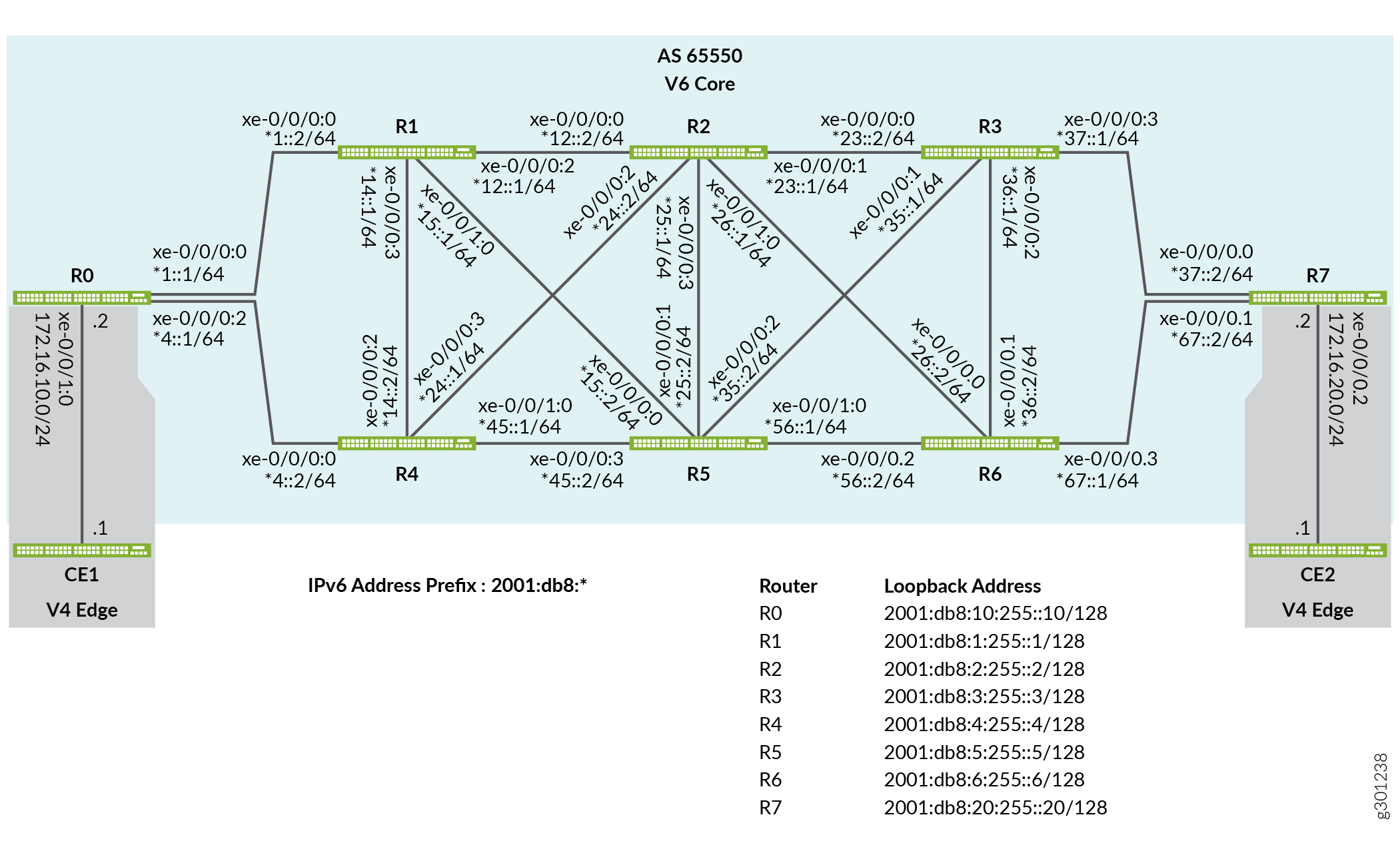
In Figure 1, Router R0 and Router R7 are ingress and egress routers that support IPv4 only devices CE1 and CE2. Routers R1, R2, R3, R4, R5, and R6 comprise an IPv6 only provider core network. All routers belong to the same autonomous system. IS-IS is the interior gateway protocol in the IPv6 core and is configured to support SRv6. In this example the Router R2 is configured as an IPv6 route reflector with IBGP peering sessions to both R0 and R7. No other routers speak BGP in this example.
To better demonstrate SRv6 tunneling this example is based on a pure IPv6 provider core. SRv6 is supported with a dual stack core where both IPv6 and IPv4 are deployed.
The edge routers that support IPv4 devices need to transport IPv4 traffic using IPv6 tunnel encapsulation. The encapsulation tunnels are derived from SRv6 SIDs configured at SRv6-enabled routers. The IS-IS protocol processes these SRv6 SIDs and updates the inet6.3 table with the next-hop addresses of the available tunnel endpoints. When an IPv4 route is learned through BGP the router attempts to resolve the associated next hop through the inet6.3 table. When a matching entry is found the result is an automatic IPv6 tunnel to the endpoint that advertised the BGP route.
In this example both the R0 and R7 routers advertise their attached IPv4 subnet using BGP. This results in IPv6 tunnels between the edge routers. The tunnels are used to transport the IPv4 traffic over the IPv6 provider core. At egress, the edge routers decapsulate the outer IPv6 header and perform an IPv4 route lookup to forward the packet to its destination.
Configuration
CLI Quick Configuration
To quickly configure this example, copy the following commands, paste them into a text file, remove any line breaks, change any details necessary to match your network configuration, copy and paste the commands into the CLI at the [edit] hierarchy level, and then enter commit from configuration mode.
Router R0
set interfaces xe-0/0/0:0 description To_R1
set interfaces xe-0/0/0:0 mtu 4000
set interfaces xe-0/0/0:0 unit 0 family iso
set interfaces xe-0/0/0:0 unit 0 family inet6 address 2001:db8:1::1/64
set interfaces xe-0/0/0:2 description To_R4
set interfaces xe-0/0/0:2 mtu 4000
set interfaces xe-0/0/0:2 unit 0 family iso
set interfaces xe-0/0/0:2 unit 0 family inet6 address 2001:db8:4::1/64
set interfaces xe-0/0/1:0 description To_CE1
set interfaces xe-0/0/1:0 unit 0 family inet address 172.16.10.2/24
set interfaces xe-0/0/1:0 unit 0 family iso
set interfaces lo0 unit 0 family iso address 49.0001.000a.0a0a.0a00
set interfaces lo0 unit 0 family inet6 address 2001:db8:10:255::10/128
set policy-options policy-statement pplb then load-balance per-packet
set routing-options source-packet-routing srv6 locator myloc 2001:db8:0:a0::/64
set routing-options forwarding-table export pplb
set routing-options router-id 172.16.255.10
set policy-options policy-statement CE1_v4 term 1 from protocol direct
set policy-options policy-statement CE1_v4 term 1 from route-filter 172.16.10.0/24 exact
set policy-options policy-statement CE1_v4 term 1 then next-hop 2001:db8:0:a0:d01::
set policy-options policy-statement CE1_v4 term 1 then accept
set routing-options autonomous-system 65550
set protocols bgp group to-R2RRv6 type internal
set protocols bgp group to-R2RRv6 export CE1_v4
set protocols bgp group to-R2RRv6 local-address 2001:db8:10:255::10
set protocols bgp group to-R2RRv6 neighbor 2001:db8:2:255::2 family inet unicast extended-nexthop
set protocols isis interface xe-0/0/0:0.0 level 2 srv6-adjacency-segment protected locator myloc end-x-sid 2001:db8:0:a0:1a01:: flavor psp
set protocols isis interface xe-0/0/0:0.0 node-link-protection
set protocols isis interface xe-0/0/0:0.0 point-to-point
set protocols isis interface xe-0/0/0:2.0 level 2 srv6-adjacency-segment protected locator myloc end-x-sid 2001:db8:0:a0:1a04:: flavor psp
set protocols isis interface xe-0/0/0:2.0 node-link-protection
set protocols isis interface xe-0/0/0:2.0 point-to-point
set protocols isis interface lo0.0 passive
set protocols isis source-packet-routing srv6 locator myloc end-sid 2001:db8:0:a0:d01:: flavor usd
set protocols isis level 1 disable
Router R1
set interfaces xe-0/0/0:0 description To_R0
set interfaces xe-0/0/0:0 mtu 4000
set interfaces xe-0/0/0:0 unit 0 family iso
set interfaces xe-0/0/0:0 unit 0 family inet6 address 2001:db8:1::2/64
set interfaces xe-0/0/0:2 description To_R2
set interfaces xe-0/0/0:2 mtu 4000
set interfaces xe-0/0/0:2 unit 0 family iso
set interfaces xe-0/0/0:2 unit 0 family inet6 address 2001:db8:12:1/64
set interfaces xe-0/0/0:3 description to-R4
set interfaces xe-0/0/0:3 mtu 4000
set interfaces xe-0/0/0:3 unit 0 family iso
set interfaces xe-0/0/0:3 unit 0 family inet6 address 2001:db8:14::1/64
set interfaces xe-0/0/1:0 description to-R5
set interfaces xe-0/0/1:0 mtu 4000
set interfaces xe-0/0/1:0 unit 0 family iso
set interfaces xe-0/0/1:0 unit 0 family inet6 address 2001:db8:15::1/64
set interfaces lo0 unit 0 family iso address 49.0001.0001.0101.0100
set interfaces lo0 unit 0 family inet6 address 2001:db8:1:255::1/128
set policy-options policy-statement pplb then load-balance per-packet
set routing-options source-packet-routing srv6 locator myloc 2001:db8:0:a1::/64
set routing-options forwarding-table export pplb
set routing-options router-id 192.168.255.1
set protocols isis interface xe-0/0/0:0.0 level 2 srv6-adjacency-segment protected locator myloc end-x-sid 2001:db8:0:a1:1a10:: flavor psp
set protocols isis interface xe-0/0/0:0.0 node-link-protection
set protocols isis interface xe-0/0/0:0.0 point-to-point
set protocols isis interface xe-0/0/0:2.0 level 2 srv6-adjacency-segment protected locator myloc end-x-sid 2001:db8:0:a1:1a12:: flavor psp
set protocols isis interface xe-0/0/0:2.0 node-link-protection
set protocols isis interface xe-0/0/0:2.0 point-to-point
set protocols isis interface xe-0/0/0:2.1 node-link-protection
set protocols isis interface xe-0/0/0:3.0 level 2 srv6-adjacency-segment protected locator myloc end-x-sid 2001:db8:0:a1:1a14:: flavor psp
set protocols isis interface xe-0/0/0:3.0 node-link-protection
set protocols isis interface xe-0/0/0:3.0 point-to-point
set protocols isis interface xe-0/0/1:0.0 level 2 srv6-adjacency-segment protected locator myloc end-x-sid 2001:db8:0:a1:1a15:: flavor psp
set protocols isis interface xe-0/0/1:0.0 node-link-protection
set protocols isis interface xe-0/0/1:0.0 point-to-point
set protocols isis interface lo0.0 passive
set protocols isis source-packet-routing srv6 locator myloc end-sid 2001:db8:0:a1:d11:: flavor usd
set protocols isis level 1 disable
Router R2
set interfaces xe-0/0/0:0 description To_R1
set interfaces xe-0/0/0:0 mtu 4000
set interfaces xe-0/0/0:0 unit 0 family iso
set interfaces xe-0/0/0:0 unit 0 family inet6 address 2001:db8:12::2/64
set interfaces xe-0/0/0:1 description To_R3
set interfaces xe-0/0/0:1 mtu 4000
set interfaces xe-0/0/0:1 unit 0 family iso
set interfaces xe-0/0/0:1 unit 0 family inet6 address 2001:db8:23::1/64
set interfaces xe-0/0/0:2 description To_R4
set interfaces xe-0/0/0:2 mtu 4000
set interfaces xe-0/0/0:2 unit 0 family iso
set interfaces xe-0/0/0:2 unit 0 family inet6 address 2011:db8:24::1/64
set interfaces xe-0/0/0:3 description To_R5
set interfaces xe-0/0/0:3 mtu 4000
set interfaces xe-0/0/0:3 unit 0 family iso
set interfaces xe-0/0/0:3 unit 0 family inet6 address 2001:db8:25::1/64
set interfaces xe-0/0/1:0 description To_R6
set interfaces xe-0/0/1:0 mtu 4000
set interfaces xe-0/0/1:0 unit 0 family iso
set interfaces xe-0/0/1:0 unit 0 family inet6 address 2001:db8:26::1/64
set interfaces lo0 unit 0 family iso address 49.0001.0002.0202.0200
set interfaces lo0 unit 0 family inet6 address 2001:db8:2:255::2/128
set policy-options policy-statement pplb then load-balance per-packet
set routing-options source-packet-routing srv6 locator myloc 2001:db8:0:a2::/64
set routing-options forwarding-table export pplb
set routing-options router-id 192.168.255.2
set routing-options autonomous-system 65550
set protocols bgp group RRv6 type internal
set protocols bgp group RRv6 local-address 2001:db8:2:255::2
set protocols bgp group RRv6 neighbor 2001:db8:10:255::10 family inet unicast extended-nexthop
set protocols bgp group RRv6 neighbor 2001:db8:20:255::20 family inet unicast extended-nexthop
set protocols bgp group RRv6 cluster 192.168.255.2
set protocols isis interface xe-0/0/0:0.0 level 2 srv6-adjacency-segment protected locator myloc end-x-sid 2001:db8:0:a2:1a21:: flavor psp
set protocols isis interface xe-0/0/0:0.0 node-link-protection
set protocols isis interface xe-0/0/0:0.0 point-to-point
set protocols isis interface xe-0/0/0:1.0 level 2 srv6-adjacency-segment protected locator myloc end-x-sid 2001:db8:0:a2:1a23:: flavor psp
set protocols isis interface xe-0/0/0:1.0 node-link-protection
set protocols isis interface xe-0/0/0:1.0 point-to-point
set protocols isis interface xe-0/0/0:2.0 level 2 srv6-adjacency-segment protected locator myloc end-x-sid 2001:db8:0:a2:1a24:: flavor psp
set protocols isis interface xe-0/0/0:2.0 node-link-protection
set protocols isis interface xe-0/0/0:2.0 point-to-point
set protocols isis interface xe-0/0/0:3.0 level 2 srv6-adjacency-segment protected locator myloc end-x-sid 2001:db8:0:a2:1a25:: flavor psp
set protocols isis interface xe-0/0/0:3.0 node-link-protection
set protocols isis interface xe-0/0/0:3.0 point-to-point
set protocols isis interface xe-0/0/1:0.0 level 2 srv6-adjacency-segment protected locator myloc end-x-sid 2001:db8:0:a2:1a26:: flavor psp
set protocols isis interface xe-0/0/1:0.0 node-link-protection
set protocols isis interface xe-0/0/1:0.0 point-to-point
set protocols isis interface lo0.0 passive
set protocols isis source-packet-routing srv6 locator myloc end-sid 2001:db8:0:a2:d21:: flavor usd
set protocols isis level 1 disable
Router R3
set interfaces xe-0/0/0:0 description To_R2
set interfaces xe-0/0/0:0 mtu 4000
set interfaces xe-0/0/0:0 unit 0 family iso
set interfaces xe-0/0/0:0 unit 0 family inet6 address 2001:db8:23::2/64
set interfaces xe-0/0/0:1 description To_R5
set interfaces xe-0/0/0:1 mtu 4000
set interfaces xe-0/0/0:1 unit 0 family iso
set interfaces xe-0/0/0:1 unit 0 family inet6 address 2001:db8:35::1/64
set interfaces xe-0/0/0:2 description To_R6
set interfaces xe-0/0/0:2 mtu 4000
set interfaces xe-0/0/0:2 unit 0 family iso
set interfaces xe-0/0/0:2 unit 0 family inet6 address 36::1/64
set interfaces xe-0/0/0:3 description To_R7
set interfaces xe-0/0/0:3 mtu 4000
set interfaces xe-0/0/0:3 unit 0 family iso
set interfaces xe-0/0/0:3 unit 0 family inet6 address 2001:db8:37::1/64
set interfaces lo0 unit 0 family iso address 49.0001.0003.0303.0300
set interfaces lo0 unit 0 family inet6 address 2001:db8:3:255::3/128
set policy-options policy-statement pplb then load-balance per-packet
set routing-options source-packet-routing srv6 locator myloc 2001:db8:0:a3::/64
set routing-options forwarding-table export pplb
set routing-options router-id 192.168.255.3
set protocols isis interface xe-0/0/0:0.0 level 2 srv6-adjacency-segment protected locator myloc end-x-sid 2001:db8:0:a3:1a32:: flavor psp
set protocols isis interface xe-0/0/0:0.0 node-link-protection
set protocols isis interface xe-0/0/0:0.0 point-to-point
set protocols isis interface xe-0/0/0:1.0 level 2 srv6-adjacency-segment protected locator myloc end-x-sid 2001:db8:0:a3:1a35:: flavor psp
set protocols isis interface xe-0/0/0:1.0 node-link-protection
set protocols isis interface xe-0/0/0:1.0 point-to-point
set protocols isis interface xe-0/0/0:2.0 level 2 srv6-adjacency-segment protected locator myloc end-x-sid 2001:db8:0:a3:1a36:: flavor psp
set protocols isis interface xe-0/0/0:2.0 node-link-protection
set protocols isis interface xe-0/0/0:2.0 point-to-point
set protocols isis interface xe-0/0/0:3.0 level 2 srv6-adjacency-segment protected locator myloc end-x-sid 2001:db8:0:a3:1a37:: flavor psp
set protocols isis interface xe-0/0/0:3.0 node-link-protection
set protocols isis interface xe-0/0/0:3.0 point-to-point
set protocols isis interface lo0.0 passive
set protocols isis source-packet-routing srv6 locator myloc end-sid 2001:db8:0:a3:d31:: flavor usd
set protocols isis level 1 disable
Router R4
set interfaces xe-0/0/0:0 description To_R0
set interfaces xe-0/0/0:0 mtu 4000
set interfaces xe-0/0/0:0 unit 0 family iso
set interfaces xe-0/0/0:0 unit 0 family inet6 address 2001:db8:4::2/64
set interfaces xe-0/0/0:2 description To_R1
set interfaces xe-0/0/0:2 mtu 4000
set interfaces xe-0/0/0:2 unit 0 family iso
set interfaces xe-0/0/0:2 unit 0 family inet6 address 2001:db8:14::2/64
set interfaces xe-0/0/0:3 description To_R2
set interfaces xe-0/0/0:3 mtu 4000
set interfaces xe-0/0/0:3 unit 0 family iso
set interfaces xe-0/0/0:3 unit 0 family inet6 address 2001:db8:24::2/64
set interfaces xe-0/0/1:0 description To_R5
set interfaces xe-0/0/1:0 mtu 4000
set interfaces xe-0/0/1:0 unit 0 family iso
set interfaces xe-0/0/1:0 unit 0 family inet6 address 2001:db8:25::1/64
set interfaces lo0 unit 0 family iso address 49.0001.0004.0404.0400
set interfaces lo0 unit 0 family inet6 address 2001:db8:4:255::4/128
set policy-options policy-statement pplb then load-balance per-packet
set routing-options source-packet-routing srv6 locator myloc 2001:db8:0:a4::/64
set routing-options forwarding-table export pplb
set routing-options router-id 192.168.255.4
set protocols isis interface xe-0/0/0:0.0 level 2 srv6-adjacency-segment protected locator myloc end-x-sid 2001:db8:0:a4:1a40:: flavor psp
set protocols isis interface xe-0/0/0:0.0 node-link-protection
set protocols isis interface xe-0/0/0:0.0 point-to-point
set protocols isis interface xe-0/0/0:2.0 level 2 srv6-adjacency-segment protected locator myloc end-x-sid 2001:db8:0:a4:1a41:: flavor psp
set protocols isis interface xe-0/0/0:2.0 node-link-protection
set protocols isis interface xe-0/0/0:2.0 point-to-point
set protocols isis interface xe-0/0/0:3.0 level 2 srv6-adjacency-segment protected locator myloc end-x-sid 2001:db8:0:a4:1a42:: flavor psp
set protocols isis interface xe-0/0/0:3.0 node-link-protection
set protocols isis interface xe-0/0/0:3.0 point-to-point
set protocols isis interface xe-0/0/1:0.0 level 2 srv6-adjacency-segment protected locator myloc end-x-sid 2001:db8:0:a4:1a45:: flavor psp
set protocols isis interface xe-0/0/1:0.0 node-link-protection
set protocols isis interface xe-0/0/1:0.0 point-to-point
set protocols isis interface lo0.0 passive
set protocols isis source-packet-routing srv6 locator myloc end-sid 2001:db8:0:a4:d41:: flavor usd
set protocols isis level 1 disable
Router R5
set interfaces xe-0/0/0:0 description To_R1
set interfaces xe-0/0/0:0 mtu 4000
set interfaces xe-0/0/0:0 unit 0 family iso
set interfaces xe-0/0/0:0 unit 0 family inet6 address 2001:db8:15::2/64
set interfaces xe-0/0/0:1 description To_R2
set interfaces xe-0/0/0:1 mtu 4000
set interfaces xe-0/0/0:1 unit 0 family iso
set interfaces xe-0/0/0:1 unit 0 family inet6 address 2001:db8:25::2/64
set interfaces xe-0/0/0:2 description To_R3
set interfaces xe-0/0/0:2 mtu 4000
set interfaces xe-0/0/0:2 unit 0 family iso
set interfaces xe-0/0/0:2 unit 0 family inet6 address 2001:db8:35::2/64
set interfaces xe-0/0/0:3 description To_R4
set interfaces xe-0/0/0:3 mtu 4000
set interfaces xe-0/0/0:3 unit 0 family iso
set interfaces xe-0/0/0:3 unit 0 family inet6 address 2001:db8:45::2/64
set interfaces xe-0/0/1:0 description To_R6
set interfaces xe-0/0/1:0 mtu 4000
set interfaces xe-0/0/1:0 unit 0 family iso
set interfaces xe-0/0/1:0 unit 0 family inet6 address 2001:db8:56::1/64
set interfaces lo0 unit 0 family iso address 49.0001.0005.0505.0500
set interfaces lo0 unit 0 family inet6 address 2001:db8:5:255::5/128
set policy-options policy-statement pplb then load-balance per-packet
set routing-options source-packet-routing srv6 locator myloc 2001:db8:0:a5::/64
set routing-options forwarding-table export pplb
set routing-options router-id 192.168.255.5
set protocols isis interface xe-0/0/0:0.0 level 2 srv6-adjacency-segment protected locator myloc end-x-sid 2001:db8:0:a5:1a51:: flavor psp
set protocols isis interface xe-0/0/0:0.0 node-link-protection
set protocols isis interface xe-0/0/0:0.0 point-to-point
set protocols isis interface xe-0/0/0:1.0 level 2 srv6-adjacency-segment protected locator myloc end-x-sid 2001:db8:0:a5:1a52:: flavor psp
set protocols isis interface xe-0/0/0:1.0 node-link-protection
set protocols isis interface xe-0/0/0:1.0 point-to-point
set protocols isis interface xe-0/0/0:2.0 level 2 srv6-adjacency-segment protected locator myloc end-x-sid 2001:db8:0:a5:1a53:: flavor psp
set protocols isis interface xe-0/0/0:2.0 node-link-protection
set protocols isis interface xe-0/0/0:2.0 point-to-point
set protocols isis interface xe-0/0/0:3.0 level 2 srv6-adjacency-segment protected locator myloc end-x-sid 2001:db8:0:a5:1a54:: flavor psp
set protocols isis interface xe-0/0/0:3.0 node-link-protection
set protocols isis interface xe-0/0/0:3.0 point-to-point
set protocols isis interface xe-0/0/1:0.0 level 2 srv6-adjacency-segment protected locator myloc end-x-sid 2001:db8:0:a5:1a56:: flavor psp
set protocols isis interface xe-0/0/1:0.0 node-link-protection
set protocols isis interface xe-0/0/1:0.0 point-to-point
set protocols isis interface lo0.0 passive
set protocols isis source-packet-routing srv6 locator myloc end-sid 2001:db8:0:a5:d51:: flavor usd
set protocols isis level 1 disable
Router R6
set interfaces xe-0/0/0:0 description To_R2
set interfaces xe-0/0/0:0 mtu 4000
set interfaces xe-0/0/0:0 unit 0 family iso
set interfaces xe-0/0/0:0 unit 0 family inet6 address 2001:db8:26::2/64
set interfaces xe-0/0/0:1 description To_R3
set interfaces xe-0/0/0:1 mtu 4000
set interfaces xe-0/0/0:1 unit 0 family iso
set interfaces xe-0/0/0:1 unit 0 family inet6 address 2001:db8:36::2/128
set interfaces xe-0/0/0:2 description To_R5
set interfaces xe-0/0/0:2 mtu 4000
set interfaces xe-0/0/0:2 unit 0 family iso
set interfaces xe-0/0/0:2 unit 0 family inet6 address 2001:db8:56::2/128
set interfaces xe-0/0/0:3 description To_R7
set interfaces xe-0/0/0:3 mtu 4000
set interfaces xe-0/0/0:3 unit 0 family iso
set interfaces xe-0/0/0:3 unit 0 family inet6 address 2001:db8:67::1/128
set interfaces lo0 unit 0 family iso address 49.0001.0006.0606.0600
set interfaces lo0 unit 0 family inet6 address 2001:db8:6:255::6/128
set policy-options policy-statement pplb then load-balance per-packet
set routing-options source-packet-routing srv6 locator myloc 2001:db8:0:a6::/64
set routing-options forwarding-table export pplb
set routing-options router-id 192.168.255.6
set protocols isis interface xe-0/0/0:0.0 level 2 srv6-adjacency-segment protected locator myloc end-x-sid 2001:db8:0:a6:1a62:: flavor psp
set protocols isis interface xe-0/0/0:0.0 node-link-protection
set protocols isis interface xe-0/0/0:0.0 point-to-point
set protocols isis interface xe-0/0/0:1.0 level 2 srv6-adjacency-segment protected locator myloc end-x-sid 2001:db8:0:a6:1a63:: flavor psp
set protocols isis interface xe-0/0/0:1.0 node-link-protection
set protocols isis interface xe-0/0/0:1.0 point-to-point
set protocols isis interface xe-0/0/0:2.0 level 2 srv6-adjacency-segment protected locator myloc end-x-sid 2001:db8:0:a6:1a65:: flavor psp
set protocols isis interface xe-0/0/0:2.0 node-link-protection
set protocols isis interface xe-0/0/0:2.0 point-to-point
set protocols isis interface xe-0/0/0:3.0 level 2 srv6-adjacency-segment protected locator myloc end-x-sid 2001:db8:0:a6:1a67:: flavor psp
set protocols isis interface xe-0/0/0:3.0 node-link-protection
set protocols isis interface xe-0/0/0:3.0 point-to-point
set protocols isis interface lo0.0 passive
set protocols isis source-packet-routing srv6 locator myloc end-sid 2001:db8:0:a6:d61:: flavor usd
set protocols isis level 1 disable
Router R7
set interfaces xe-0/0/0:0 description To_R3
set interfaces xe-0/0/0:0 mtu 4000
set interfaces xe-0/0/0:0 unit 0 family iso
set interfaces xe-0/0/0:0 unit 0 family inet6 address 2001:db8:37::2/64
set interfaces xe-0/0/0:1 description To_R6
set interfaces xe-0/0/0:1 mtu 4000
set interfaces xe-0/0/0:1 unit 0 family iso
set interfaces xe-0/0/0:1 unit 0 family inet6 address 2001:db8:67::2/128
set interfaces xe-0/0/0:2 description To_CE2
set interfaces xe-0/0/0:2 unit 0 family inet address 172.16.20.2/24
set interfaces xe-0/0/0:2 unit 0 family iso
set interfaces lo0 unit 0 family iso address 49.0001.0007.0707.0700
set interfaces lo0 unit 0 family inet6 address 2001:db8:20:255::20/32
set policy-options policy-statement pplb then load-balance per-packet
set policy-options policy-statement CE2_v4 term 1 from protocol direct
set policy-options policy-statement CE2_v4 term 1 from route-filter 172.16.20.0/24 exact
set policy-options policy-statement CE2_v4 term 1 then next-hop 2001:db8:0:a7:d71::
set policy-options policy-statement CE2_v4 term 1 then accept
set routing-options source-packet-routing srv6 locator myloc 2001:db8:0:a7::/64
set routing-options forwarding-table export pplb
set routing-options router-id 172.16.255.20
set routing-options autonomous-system 65550
set protocols bgp group to-R2RRv6 type internal
set protocols bgp group to-R2RRv6 local-address 2001:db8:20:255::20
set protocols bgp group to-R2RRv6 neighbor 2001:db8:2:255::2 family inet unicast extended-nexthop
set protocols bgp group to-R2RRv6 export CE2_v4
set protocols isis interface xe-0/0/0:0.0 level 2 srv6-adjacency-segment protected locator myloc end-x-sid 2001:db8:0:a7:1a73:: flavor psp
set protocols isis interface xe-0/0/0:0.0 node-link-protection
set protocols isis interface xe-0/0/0:0.0 point-to-point
set protocols isis interface xe-0/0/0:1.0 level 2 srv6-adjacency-segment protected locator myloc end-x-sid 2001:db8:0:a7:1a76:: flavor psp
set protocols isis interface xe-0/0/0:1.0 node-link-protection
set protocols isis interface xe-0/0/0:1.0 point-to-point
set protocols isis interface lo0.0 passive
set protocols isis source-packet-routing srv6 locator myloc end-sid 2001:db8:0:a7:d71:: flavor usd
set protocols isis level 1 disable
Configuring Router R0
The following example requires that you navigate various levels in the configuration hierarchy. For information about navigating the CLI, see Using the CLI Editor in Configuration Mode in the CLI User Guide.
To configure SRv6 network programming to support IPv4 tunnels over a IPv6 core, perform the following steps on the R0 router:
Step-by-Step Procedure
-
Configure the device interfaces to enable IP transport.
[edit]
user@R0# set interfaces xe-0/0/0:0 description To_R1_1
user@R0# set interfaces xe-0/0/0:0 vlan-tagging
user@R0# set interfaces xe-0/0/0:0 unit 0 vlan-id 1
user@R0# set interfaces xe-0/0/0:0 unit 0 family inet address 10.11.1.1/24
user@R0# set interfaces xe-0/0/0:0 unit 0 family iso
user@R0# set interfaces xe-0/0/0:0 unit 0 family inet6 address 2001:db8:1001::1/32
user@R0# set interfaces xe-0/0/0:2 description To_R4_1
user@R0# set interfaces xe-0/0/0:2 vlan-tagging
user@R0# set interfaces xe-0/0/0:2 unit 0 vlan-id 1
user@R0# set interfaces xe-0/0/0:2 unit 0 family inet address 10.21.1.1/24
user@R0# set interfaces xe-0/0/0:2 unit 0 family iso
user@R0# set interfaces xe-0/0/0:2 unit 0 family inet6 address 2001:db8:2021::1/32
user@R0# set interfaces xe-0/0/1:0 description to_RT
user@R0# set interfaces xe-0/0/1:0 vlan-tagging
user@R0# set interfaces xe-0/0/1:0 unit 1 vlan-id 1
user@R0# set interfaces xe-0/0/1:0 unit 1 family inet address 172.20.1.1/24
user@R0# set interfaces xe-0/0/1:0 unit 1 family iso
user@R0# set interfaces xe-0/0/1:0 unit 1 family inet6 address 2001:db8::20:1:1:1/120
user@R0# set interfaces xe-0/0/1:0 unit 4 vlan-id 4
user@R0# set interfaces xe-0/0/1:0 unit 4 family inet address 172.20.2.1/24
user@R0# set interfaces xe-0/0/1:0 unit 4 family iso
user@R0# set interfaces xe-0/0/1:0 unit 4 family inet6 address 2001:db8::20:2:1:1/120
-
Configure the loopback interface with IPv4 and IPv6 addresses that is used as router ID for BGP sessions.
[edit]
user@R0# set interfaces lo0 unit 0 family inet address 192.168.0.10/32
user@R0# set interfaces lo0 unit 0 family iso address 49.0001.000a.0a0a.0a00
user@R0# set interfaces lo0 unit 0 family inet6 address 2001:db8::10:10:10:10/32
-
Configure the router ID and autonomous system (AS) number to propagate routing information within a set of routing devices that belong to the same AS.
[edit]
user@R0# set routing-options router-id 10.10.10.10
user@R0# set routing-options autonomous-system 65550
-
Enable SRv6 globally and the locator address to indicate the SRv6 capability of the router. SRv6 SID is an IPv6 address that consists of the locator and a function. The routing protocols advertise the locator addresses.
[edit]
user@R0# set routing-options source-packet-routing srv6 locator myloc 2001:db8:0:a0::/64
-
Configure the End-Sid function for the prefix segments. Specify a flavor, that is the behavior of the End-SID function as per your network requirements. Penultimate Segment Pop (PSP), Ultimate Segment Pop (USP), and Ultimate Segment Decapsulation (USP) are the three available flavors for SRv6 functions.
Note:Ensure that the locator and the End-SID are in the same subnet to avoid a commit error.
[edit]
user@R0# set protocols isis source-packet-routing srv6 locator myloc end-sid 2001:db8:0:a0:d01:: flavor usd
user@R0# set protocols isis source-packet-routing srv6 locator myloc1 end-sid 2001:db8:0:a10:d01:: flavor usd
user@R0# set protocols isis source-packet-routing srv6 locator myloc2 end-sid 2001:db8:0:a20:d01:: flavor usd
user@R0# set protocols isis source-packet-routing srv6 locator myloc3 end-sid 2001:db8:0:a30:d01:: flavor usd
user@R0# set protocols isis source-packet-routing srv6 locator myloc4 end-sid 2001:db8:0:a40:d01:: flavor usp
user@R0# set protocols isis source-packet-routing srv6 locator myloc4 end-sid 2001:db8:0:a40:d01:: flavor usd
user@R0# set protocols isis level 1 disable
-
Configure End-X-SID function on the point-to-point (P2P) interface for the adjacency segments. Specify one or more flavor for the End-X-SID.
Note:Ensure that the Locator and End-X-SID are in the same subnet to avoid a commit error. You must enable SRv6 and configure the locator at the
Whenever you configure an[edit routing-options]before mapping locators to interfaces.srv6-adjacency-segmentyou must also configure the related locator under theprotocols isis source-packet-routing srv6 locatorhierarchy, as shown in step 5.[edit] user@R0# set protocols isis interface xe-0/0/0:0.0 level 2 srv6-adjacency-segment protected locator myloc end-x-sid 2001:db8:0:a0:1a01:: flavor usd user@R0# set protocols isis interface xe-0/0/0:0.0 level 2 srv6-adjacency-segment protected locator myloc1 end-x-sid 2001:db8:0:a10:1a01:: flavor usd user@R0# set protocols isis interface xe-0/0/0:0.0 level 2 srv6-adjacency-segment protected locator myloc2 end-x-sid 2001:db8:0:a20:1a01:: flavor usd user@R0# set protocols isis interface xe-0/0/0:0.0 level 2 srv6-adjacency-segment protected locator myloc3 end-x-sid 2001:db8:0:a30:1a01:: flavor usd user@R0# set protocols isis interface xe-0/0/0:0.0 level 2 srv6-adjacency-segment protected locator myloc4 end-x-sid 2001:db8:0:a40:1a01:: flavor usd user@R0# set protocols isis interface xe-0/0/0:0.0 node-link-protection user@R0# set protocols isis interface xe-0/0/0:0.0 point-to-point
-
Configure SRv6 options for the adjacency segment of the LAN interface xe-0/0/0:2.0. Specify a flavor as per your network requirements. Penultimate Segment Pop (PSP), Ultimate Segment Pop (USP), and Ultimate Segment Decapsulation (USP) are the three available flavors for the SRv6 adjacency segment.
Note:Ensure that the Locator and End-X-Sid are in the same subnet to avoid a commit error. You must enable SRv6 and configure the locator at the
[edit routing-options]before mapping locators to interfaces.[edit] user@R0# set protocols isis interface xe-0/0/0:2.0 level 2 lan-neighbor 0100.0404.0404 srv6-adjacency-segment unprotected locator myloc end-x-sid 2001:db8:0:a0:1a04:: flavor usd user@R0# set protocols isis interface xe-0/0/0:2.0 level 2 lan-neighbor 0100.0404.0404 srv6-adjacency-segment unprotected locator myloc1 end-x-sid 2001:db8:0:a10:1a04:: flavor usd user@R0# set protocols isis interface xe-0/0/0:2.0 level 2 lan-neighbor 0100.0404.0404 srv6-adjacency-segment unprotected locator myloc2 end-x-sid 2001:db8:0:a20:1a04:: flavor usd user@R0# set protocols isis interface xe-0/0/0:2.0 level 2 lan-neighbor 0100.0404.0404 srv6-adjacency-segment unprotected locator myloc3 end-x-sid 2001:db8:0:a30:1a04:: flavor usd user@R0# set protocols isis interface xe-0/0/0:2.0 level 2 lan-neighbor 0100.0404.0404 srv6-adjacency-segment unprotected locator myloc4 end-x-sid 2001:db8:0:a40:1a04:: flavor usd user@R0# set protocols isis interface xe-0/0/0:2.0 node-link-protection user@R0# set protocols isis interface xe-0/0/1:0.1 user@R0# set protocols isis interface fxp0.0 disable user@R0# set protocols isis interface lo0.0 passive
-
Configure BGP on the core-facing interface to establish internal peering sessions.
[edit]
user@R0# set protocols bgp group to-PEv6 type internal
user@R0# set protocols bgp group to-PEv6 local-address abcd::10:10:10:10
user@R0# set protocols bgp group to-PEv6 neighbor abcd::2:2:2:2 family inet unicast extended-nexthop
user@R0# set protocols bgp group to-PE2 type internal
user@R0# set protocols bgp group to-PE2 local-address 10.10.10.10
user@R0# set protocols bgp group to-PE2 neighbor 2.2.2.2 family inet6 unicast
user@R0# set protocols bgp group to-PE2 neighbor 2.2.2.2 family inet6-vpn unicast
-
Define a policy to load balance packets.
[edit]
user@R0# set policy-options policy-statement pplb then load-balance per-packet
-
Apply the per-packet policy to enable load balancing of traffic.
[edit]
user@R0# set routing-options forwarding-table export pplb
Results
From configuration mode, confirm your configuration by entering the show interfaces, show protocols, show policy-options, and show routing-options commands. If the output does not display the intended configuration, repeat the instructions in this example to correct the configuration.
[edit]
user@R0# show interfaces
xe-0/0/0:0 {
    description To_R1;
    mtu 4000;
    unit 0 {
        family iso;
        family inet6 {
            address 2001:db8:1::1/64;
        }
    }
}
xe-0/0/0:2 {
    description To_R4;
    mtu 4000;
    unit 0 {
        family iso;
        family inet6 {
            address 2001:db8:4::1/64;
        }
    }
}
xe-0/0/1:0 {
    description To_CE1;
    unit 0 {
        family inet {
            address 172.16.10.2/24;
        }
        family iso;
    }
}
lo0 {
    unit 0 {
        family iso {
            address 49.0001.000a.0a0a.0a00;
        }
        family inet6 {
            address 2001:db8:10:255::10/128;
        }
    }
}
[edit]
user@R0# show protocols
bgp {
    group to-R2RRv6 {
        type internal;
        local-address 2001:db8:10:255::10;
        export CE1_v4;
        neighbor 2001:db8:2:255::2 {
            family inet {
                unicast {
                    extended-nexthop;
                }
            }
        }
    }
}
isis {
    interface xe-0/0/0:0.0 {
        level 2 {
            srv6-adjacency-segment {
                protected {
                    locator myloc {
                        end-x-sid 2001:db8:0:a0:1a01:: {
                            flavor psp;
                        }
                    }
                }
            }
        }
        node-link-protection;
        point-to-point;
    }
    interface xe-0/0/0:2.0 {
        level 2 {
            srv6-adjacency-segment {
                protected {
                    locator myloc {
                        end-x-sid 2001:db8:0:a0:1a04:: {
                            flavor psp;
                        }
                    }
                }
            }
        }
        node-link-protection;
        point-to-point;
    }
    interface lo0.0 {
        passive;
    }
    source-packet-routing {
        srv6 {
            locator myloc {
                end-sid 2001:db8:0:a0:d01:: {
                    flavor {
                        usd;
                    }
                }
            }
        }
    }
    level 1 disable;
}
[edit]
user@R0# show policy-options
policy-statement CE1_v4 {
    term 1 {
        from {
            protocol direct;
            route-filter 172.16.10.0/24 exact;
        }
        then {
            next-hop 2001:db8:0:a0:d01::;
            accept;
        }
    }
}
policy-statement pplb {
    then {
        load-balance per-packet;
    }
}
[edit]
user@R0# show routing-options
source-packet-routing {
    srv6 {
        locator myloc 2001:db8:0:a0::/64;
    }
}
forwarding-table {
    export pplb;
}
router-id 172.16.255.10;
autonomous-system 65550;
When done configuring the device, enter commit from configuration mode.
Verification
Confirm that the configuration is working properly.
- Verifying IS-IS Adjacency and IBGP Session
- Verify SRv6 is Enabled
- Verify the SRv6 End-X-SID Configuration
- Verifying the Locator Route is Installed
- Verifying the End-X-SID Route is Installed
- Verifying the End-SID Route is Installed
- Verify the SRv6 Configuration in the IS-IS Database
- Verifying the Route to CE2 Uses an SRv6 Tunnel
- Test IPv4 Connectivity Between CE1 and CE2
Verifying IS-IS Adjacency and IBGP Session
Purpose
Verify IS-IS adjacencies and IBGP session at R2. R2 is chosen for this task because it has 5 adjacencies and also serves as the router reflector for the BGP control plane.
Its a good idea to confirm the IS-IS adjacencies on all routers before proceeding to the remaining verification steps. A successful SRv6 deployment requires that the interior gateway protocol is operational on all nodes.
Action
From operational mode, run the show isis adjacency command on router R2.
user@R2> show isis adjacency
Interface             System         L State        Hold (secs) SNPA
xe-0/0/0:0.0          R1             2  Up                   26
xe-0/0/0:1.0          R3             2  Up                   25
xe-0/0/0:2.0          R4             2  Up                   25
xe-0/0/0:3.0          R5             2  Up                   24
xe-0/0/1:0.0          R6             2  Up                   18
From operational mode, run the show bgp summary command on router R2.
user@R2> show bgp summary
Threading mode: BGP I/O
Default eBGP mode: advertise - accept, receive - accept
Groups: 1 Peers: 2 Down peers: 0
Table          Tot Paths  Act Paths Suppressed    History Damp State    Pending
inet.0
                       2          2          0          0          0          0
inet6.0
                       0          0          0          0          0          0
Peer                     AS      InPkt     OutPkt    OutQ   Flaps Last Up/Dwn State|#Active/Received/Accepted/Damped...
2001:db8:10:255::10       65550       3101       3092       0       0    23:14:18 Establ
  inet.0: 1/1/1/0
2001:db8:20:255::20       65550       3091       3080       0       0    23:10:10 Establ
  inet.0: 1/1/1/0
Meaning
The output confirms the expected IS-IS adjacency count for the R2 router. It also confirms that R2 has established IPv6 based BGP sessions to both the R0 and R7 routers.
Verify SRv6 is Enabled
Purpose
Verify that SRv6 is enabled with a locator, End-SID, and flavor on Router R0.
Action
From operational mode, run the show isis overview command on Router R0.
user@R0> show isis overview
Instance: master
  Router ID: 172.16.255.10
  IPv6 Router ID: 2001:db8:1::1
  Hostname: R0
  Sysid: 0100.0a0a.0a0a
  Areaid: 49.00
  Adjacency holddown: enabled
  Maximum Areas: 3
  LSP life time: 1200
  Attached bit evaluation: enabled
  SPF delay: 200 msec, SPF holddown: 5000 msec, SPF rapid runs: 3
  IPv4 is enabled, IPv6 is enabled
  Traffic engineering: enabled
  Restart: Disabled
    Helper mode: Enabled
  Layer2-map: Disabled
  Source Packet Routing (SPRING): Enabled
    Node Segments: Disabled
   SRv6: Enabled
     Locator: 2001:db8:0:a0::/64, Algorithm: 0
        END-SID: 2001:db8:0:a0:d01::, Flavor: USD
  Post Convergence Backup: Disabled
  Level 1
    Internal route preference: 15
    External route preference: 160
    Prefix export count: 0
    Wide metrics are enabled, Narrow metrics are enabled
    Source Packet Routing is enabled
  Level 2
    Internal route preference: 18
    External route preference: 165
    Prefix export count: 0
    Wide metrics are enabled, Narrow metrics are enabled
    Source Packet Routing is enabled
Meaning
The configured SRv6 locator SRv6: Enabled Locator: 2001:db8:0:a0::/64, Algorithm:
0 and , End-SID and flavor END-SID:
2001:db8:0:a0:d01::,
Flavor: USD are displayed in the output.
Verify the SRv6 End-X-SID Configuration
Purpose
Verify that an End-X-SID function and flavor are configured on R0.
Action
From operational mode, run the show isis adjacency detail command on Router R0.
user@R0> show isis adjacency detail
R1
  Interface: xe-0/0/0:0.0, Level: 2, State: Up, Expires in 19 secs
  Priority: 0, Up/Down transitions: 1, Last transition: 03:51:48 ago
  Circuit type: 2, Speaks: IP, IPv6
  Topologies: Unicast
  Restart capable: Yes, Adjacency advertisement: Advertise
  IP addresses: 192.168.255.1
  IPv6 addresses: fe80::2e6b:f5ff:fedb:e800
  IPv6 Global Interface Address: 2001:db8:1::2
  Level 2 SRv6 protected END-X-SID: 2001:db8:0:a0:1a01::
    Flavor: PSP, Flags: B-P, Algorithm: 0

R4
  Interface: xe-0/0/0:2.0, Level: 2, State: Up, Expires in 20 secs
  Priority: 0, Up/Down transitions: 1, Last transition: 03:48:04 ago
  Circuit type: 2, Speaks: IP, IPv6
  Topologies: Unicast
  Restart capable: Yes, Adjacency advertisement: Advertise
  IP addresses: 192.168.255.4
  IPv6 addresses: fe80::2e6b:f5ff:feb4:4000
  IPv6 Global Interface Address: 2001:db8:4::2
  Level 2 SRv6 protected END-X-SID: 2001:db8:0:a0:1a04::
    Flavor: PSP, Flags: B-P, Algorithm: 0
Meaning
The field SRv6 protected END-X-SID:
2001:db8:0:a0:1a01::
indicates that End-X-SID function with Flavor PSP has been
configured on router R0 for the interface used to attach to R1. Similar
output is confirmed for the interface connected to R4, which uses a
different End-X-SID.
Verifying the Locator Route is Installed
Purpose
Verify that the locator route has been installed.
Action
From operational mode, run the show route 2001:db8:0:a0::/64 detail command on router R0.
user@R0> show route 2001:db8:0:a0::/64 detail
inet6.0: 75 destinations, 75 routes (75 active, 0 holddown, 0 hidden)
+ = Active Route, - = Last Active, * = Both

2001:db8:0:a0::/64*[IS-IS/18] 3d 19:03:16, metric 0
                       Reject

user@R0> show route 2001:db8:0:a0::/64 detail
inet6.0: 45 destinations, 45 routes (45 active, 0 holddown, 0 hidden)
2001:db8:0:a0::/64 (1 entry, 1 announced)
        *IS-IS  Preference: 18
                Level: 2
                Next hop type: Reject, Next hop index: 0
                Address: 0xc54526c
                Next-hop reference count: 2
                State: <Active Int OpaqueData>
                Local AS: 65550
                Age: 22:15:32   Metric: 0
                Validation State: unverified
                ORR Generation-ID: 0
                Task: IS-IS
                Announcement bits (2): 0-KRT 5-Resolve tree 5
                AS path: I
		. . .
Meaning
The output confirms the locator route 2001:db8:0:a0::/64*[IS-IS/18] is installed in the inet6.0 table.
Verifying the End-X-SID Route is Installed
Purpose
To display the configured End-X-SID route information that is applied at the interface.
Action
From operational mode, run the show route 2001:db8:0:a0:1a01:: command on Router R0.
user@R0> show route 2001:db8:0:a0:1a01::
inet6.0: 45 destinations, 45 routes (45 active, 0 holddown, 0 hidden)
+ = Active Route, - = Last Active, * = Both

2001:db8:0:a0::1a01/128
                   *[IS-IS/18] 04:33:42, metric 0
                    >  to fe80::2e6b:f5ff:fedb:e800 via xe-0/0/0:0.0
Meaning
The output confirms the End-X-SID route 2001:db8:0:a0::1a01/128 is installed in the inet.6.0 routing table.
Verifying the End-SID Route is Installed
Purpose
Verify that the End-SID routes for all routers in the SRv6 domain are installed in the inet6.3 table at Router R0.
Action
From operational mode, run the show route table inet6.3 protocol isis command on Router R0 to see all End-SIDs the router has learned. Then display detailed information about the End-SID associated with the R7 router.
user@R0> show route table inet6.3 protocol isis
inet6.3: 7 destinations, 7 routes (7 active, 0 holddown, 0 hidden)
+ = Active Route, - = Last Active, * = Both

2001:db8:0:a1::d11/128
                   *[SRV6-ISIS/14] 04:39:22, metric 10
                    >  to fe80::2e6b:f5ff:fedb:e800 via xe-0/0/0:0.0, SRV6-Tunnel, Dest: 2001:db8:0:a1:d11::
2001:db8:0:a2::d21/128
                   *[SRV6-ISIS/14] 04:35:38, metric 20
                       to fe80::2e6b:f5ff:fedb:e800 via xe-0/0/0:0.0, SRV6-Tunnel, Dest: 2001:db8:0:a2:d21::
                    >  to fe80::2e6b:f5ff:feb4:4000 via xe-0/0/0:2.0, SRV6-Tunnel, Dest: 2001:db8:0:a2:d21::
2001:db8:0:a3::d31/128
                   *[SRV6-ISIS/14] 04:35:38, metric 30
                       to fe80::2e6b:f5ff:fedb:e800 via xe-0/0/0:0.0, SRV6-Tunnel, Dest: 2001:db8:0:a3:d31::
                    >  to fe80::2e6b:f5ff:feb4:4000 via xe-0/0/0:2.0, SRV6-Tunnel, Dest: 2001:db8:0:a3:d31::
2001:db8:0:a4::d41/128
                   *[SRV6-ISIS/14] 04:35:38, metric 10
                    >  to fe80::2e6b:f5ff:feb4:4000 via xe-0/0/0:2.0, SRV6-Tunnel, Dest: 2001:db8:0:a4:d41::
2001:db8:0:a5::d51/128
                   *[SRV6-ISIS/14] 04:35:01, metric 20
                       to fe80::2e6b:f5ff:fedb:e800 via xe-0/0/0:0.0, SRV6-Tunnel, Dest: 2001:db8:0:a5:d51::
                    >  to fe80::2e6b:f5ff:feb4:4000 via xe-0/0/0:2.0, SRV6-Tunnel, Dest: 2001:db8:0:a5:d51::
2001:db8:0:a6::d61/128
                   *[SRV6-ISIS/14] 04:34:32, metric 30
                       to fe80::2e6b:f5ff:fedb:e800 via xe-0/0/0:0.0, SRV6-Tunnel, Dest: 2001:db8:0:a6:d61::
                    >  to fe80::2e6b:f5ff:feb4:4000 via xe-0/0/0:2.0, SRV6-Tunnel, Dest: 2001:db8:0:a6:d61::
2001:db8:0:a7::d71/128
                   *[SRV6-ISIS/14] 04:33:00, metric 40
                       to fe80::2e6b:f5ff:fedb:e800 via xe-0/0/0:0.0, SRV6-Tunnel, Dest: 2001:db8:0:a7:d71::
                    >  to fe80::2e6b:f5ff:feb4:4000 via xe-0/0/0:2.0, SRV6-Tunnel, Dest: 2001:db8:0:a7:d71::

user@R0> show route 2001:db8:0:a7::d71/128 detail

inet6.3: 7 destinations, 7 routes (7 active, 0 holddown, 0 hidden)
2001:db8:0:a7::d71/128 (1 entry, 1 announced)
        *SRV6-ISIS Preference: 14
                Level: 2
                Next hop type: List, Next hop index: 1048577
                Address: 0xdb8deb4
                Next-hop reference count: 6
                Next hop: ELNH Address 0xc5462d4 weight 0x1
                    Next hop type: Chain, Next hop index: 582
                    Address: 0xc5462d4
                    Next-hop reference count: 1
                    Next hop: ELNH Address 0xc545bcc
                    SRV6-Tunnel: Reduced-SRH Encap-mode
                     Src: 2001:db8:1::1 Dest: 2001:db8:0:a7:d71::
                     Segment-list[0] 2001:db8:0:a7:d71::
                        Next hop type: Router, Next hop index: 580
                        Address: 0xc545bcc
                        Next-hop reference count: 9
                        Next hop: fe80::2e6b:f5ff:fedb:e800 via xe-0/0/0:0.0 weight 0x1
                Next hop: ELNH Address 0xc546338 weight 0x1, selected
                    Next hop type: Chain, Next hop index: 583
                    Address: 0xc546338
                    Next-hop reference count: 1
                    Next hop: ELNH Address 0xc545f50
                    SRV6-Tunnel: Reduced-SRH Encap-mode
                     Src: 2001:db8:1::1 Dest: 2001:db8:0:a7:d71::
                     Segment-list[0] 2001:db8:0:a7:d71::
                        Next hop type: Router, Next hop index: 581
                        Address: 0xc545f50
                        Next-hop reference count: 9
                        Next hop: fe80::2e6b:f5ff:feb4:4000 via xe-0/0/0:2.0 weight 0x1
                State: <Active NoReadvrt Int OpaqueData>
                Local AS: 65550
                Age: 4:35:43    Metric: 40
                Validation State: unverified
                ORR Generation-ID: 0
                Task: IS-IS
                Announcement bits (3): 0-Resolve tree 2 1-Resolve tree 5 2-Resolve_IGP_FRR task
                AS path: I
                Session-IDs associated:
                Session-id: 322 Version: 0
Meaning
The output confirms that Router R0 has learned End-SIDs, that is,
2001:db8:0:a1::d11/128 and
2001:db8:0:a2::d21/128, from all other routers in the
topology. Note the End-SIDs have been installed in the
inet6.3 table. The detailed output for the End-SID
advertised by R7
2001:db8:0:a7:d71::
confirms an SRv6 tunnel has been established between Router R0 and Router
R7.
Note that the segment list is populated with the End-SID value configured on the Router R7. Recall that all End-SIDs in this example are configured with the Ultimate Segment Decapsulate (USD) flavor. It’s the combination of a local End-SID and the associated USD flavor that tells R7 it’s the egress of the IPv6 tunnel. Upon receipt R7 decapsulates the IPv4 packet and routes it according to the IPv4 destination address.
Verify the SRv6 Configuration in the IS-IS Database
Purpose
Display the IS-IS database to verify the End-SID and flavor configured at Router R7. In this example the command is executed on Router R0. Similar output is expected on all router because the IS-IS database is replicated to all nodes.
Action
From operational mode, run the show isis database R7.00-00 extensive command on Router R0.
user@R0> show isis database R.00-00 extensive
IS-IS level 1 link-state database:

IS-IS level 2 link-state database:

R7.00-00 Sequence: 0x31f, Checksum: 0x2ce6, Lifetime: 904 secs
   IS neighbor: R3.00                         Metric:       10
     Two-way fragment: R3.00-00, Two-way first fragment: R3.00-00
   IS neighbor: R6.00                         Metric:       10
     Two-way fragment: R6.00-00, Two-way first fragment: R6.00-00
   V6 prefix: 2001:db8::/32                   Metric:        0 Internal Up
   V6 prefix: 2001:db8:0:a7::/64              Metric:        0 Internal Up
   V6 prefix: 2001:db8:20:255::20/128         Metric:        0 Internal Up
   V6 prefix: 2001:db8:37::/64                Metric:       10 Internal Up
   V6 prefix: 2001:db8:67::2/128              Metric:       10 Internal Up

  Header: LSP ID: R7.00-00, Length: 445 bytes
    Allocated length: 746 bytes, Router ID: 172.16.255.20
    Remaining lifetime: 904 secs, Level: 2, Interface: 360
    Estimated free bytes: 0, Actual free bytes: 301
    Aging timer expires in: 904 secs
    Protocols: IP, IPv6

  Packet: LSP ID: R7.00-00, Length: 445 bytes, Lifetime : 1192 secs
    Checksum: 0x2ce6, Sequence: 0x31f, Attributes: 0x3 <L1 L2>
    NLPID: 0x83, Fixed length: 27 bytes, Version: 1, Sysid length: 0 bytes
    Packet type: 20, Packet version: 1, Max area: 0

  TLVs:
    Area address: 49.00 (2)
    LSP Buffer Size: 1492
    Speaks: IP
    Speaks: IPV6
    IP router id: 172.16.255.20
    IP address: 172.16.255.20
    IPv6 TE Router ID: 2001:db8:20:255::20
    Hostname: R7
    SRv6 Locator: 2001:db8:0:a7::/64, Metric: 0, MTID: 0, Flags: 0x0, Algorithm: 0
      SRv6 SID: 2001:db8:0:a7:d71::, Flavor: USD
    IPv6 prefix: 2001:db8:20:255::20/128 Metric 0 Up
    IPv6 prefix: 2001:db8::/32 Metric 0 Up
    IPv6 prefix: 2001:db8:0:a7::/64 Metric 0 Up
    IPv6 prefix: 2001:db8:37::/64 Metric 10 Up
    IPv6 prefix: 2001:db8:67::2/128 Metric 10 Up
    Router Capability:  Router ID 172.16.255.20, Flags: 0x00
      SPRING Algorithm - Algo: 0
      SRv6 Capability - Flags: 0
      Node MSD Advertisement Sub-TLV:Type:  23, Length: 10
      SRv6 Maximum Segments Left MSD:Type:  41, Value: 6
      SRv6 Maximum Pop MSD:Type:  42, Value: 7
      SRv6 Maximum Insert MSD:Type:  43, Value: 5
      SRv6 Maximum Encap MSD:Type:  44, Value: 6
      SRv6 Maximum End D MSD:Type:  45, Value: 6
      IPv6 TE Router Id: 2001:db8:20:255::20
    IS neighbor: R6.00, Internal, Metric: default 10
    IS neighbor: R3.00, Internal, Metric: default 10
    Extended IS Reachability TLV, Type: 22, Length: 174
    IS extended neighbor: R6.00, Metric: default 10 SubTLV len: 76
      IPv6 address: 2001:db8:67::2
      Neighbor's IP address: 192.168.255.6
      Neighbor's IPv6 address: 2001:db8:67::1
      Local interface index: 361, Remote interface index: 364
      P2P SRV6 END-X-SID:2001:db8:0:a7:1a76:: , Flags:B-P, Weight:0, Algorithm:0
       Flags:0xa0(B:1,S:0,P:1), Flavor: PSP
    IS extended neighbor: R3.00, Metric: default 10 SubTLV len: 76
      IPv6 address: 2001:db8:37::2
      Neighbor's IP address: 192.168.255.3
      Neighbor's IPv6 address: 2001:db8:37::1
      Local interface index: 360, Remote interface index: 336
      P2P SRV6 END-X-SID:2001:db8:0:a7:1a73:: , Flags:B-P, Weight:0, Algorithm:0
       Flags:0xa0(B:1,S:0,P:1), Flavor: PSP
  No queued transmissions
Meaning
The presence of SRv6 SID:
2001:db8:0:a7:d71::
with Flavor: USD confirms that SRv6 is enabled with a SID
decapsulate flavor on the R7 router. The output also shows that the
interfaces at R7 have been configured for TI-LFA protection using a PSP
flavor.
Verifying the Route to CE2 Uses an SRv6 Tunnel
Purpose
Display the route to the IPv4 subnet at R7 to confirm the next hop points to an SRv6 tunnel.
Action
From operational mode, run the show route 172.16.20.0/24 command on router R0.
user@R0> show route 172.16.20.0/24

inet.0: 36 destinations, 36 routes (36 active, 0 holddown, 0 hidden)
+ = Active Route, - = Last Active, * = Both

172.16.20.0/24     *[BGP/170] 05:20:58, localpref 100, from 2001:db8:2:255::2
                      AS path: I, validation-state: unverified
                       to fe80::2e6b:f5ff:fedb:e800 via xe-0/0/0:0.0, SRV6-Tunnel, Dest: 2001:db8:0:a7:d71::
                    >  to fe80::2e6b:f5ff:feb4:4000 via xe-0/0/0:2.0, SRV6-Tunnel, Dest: 2001:db8:0:a7:d71::
Meaning
The output confirms that R0 has learned the route to the 172.16.20.0/24 subnet through its BGP session to R2, which recall is configured as a route reflector in this example. The next hops confirm that an SRv6 tunnel to the R7 router has been installed for this route. Two next hops are available in keeping with their being two equal cost paths between the R0 and R7 routers in the example topology.
Test IPv4 Connectivity Between CE1 and CE2
Purpose
Generate pings to verify IPv4 connectivity between the CE devices over the IPv6 provider core.
Action
From operational mode, run the ping 172.16.20.2 source 172.16.10.2 count 2 command on router R0.
user@R0> ping 172.16.20.2 source 172.16.10.2 count 2
PING 172.16.20.2 (172.16.20.2): 56 data bytes
64 bytes from 172.16.20.2: icmp_seq=0 ttl=64 time=114.922 ms
64 bytes from 172.16.20.2: icmp_seq=1 ttl=64 time=89.558 ms

--- 172.16.20.2 ping statistics ---
2 packets transmitted, 2 packets received, 0% packet loss
round-trip min/avg/max/stddev = 89.558/102.240/114.922/12.682 ms
Meaning
The output confirms IPv4 connectivity is working between the CE device networks. This provides verification that SRv6 tunneling over an IPv6 provider core is working properly in this example.