ON THIS PAGE
Example: Enable IS-IS Link Delay with Source Packet Routing in Networking (SPRING) in a Layer 3 Virtual Private Network (VPN)
This example shows how to configure IS-IS link delay with SPRING in a Layer3 VPN scenario. In the example, you can create two VPNs between PE1 and PE2. VPN1 optimizes link delay and VPN2 optimizes IGP metric. Although you can configure the feature to enable bidirectional traffic in the test topology, we're focusing on a unidirectional traffic scenario in this example. Specifically, your task is to control the forwarding path for Layer 3 VPN traffic sent by PE1 to destinations advertised by PE2.
Requirements
This example uses the following hardware and software components:
-
Four MX Series routers
-
Junos OS Release 21.1R1 or later running on all devices
Topology
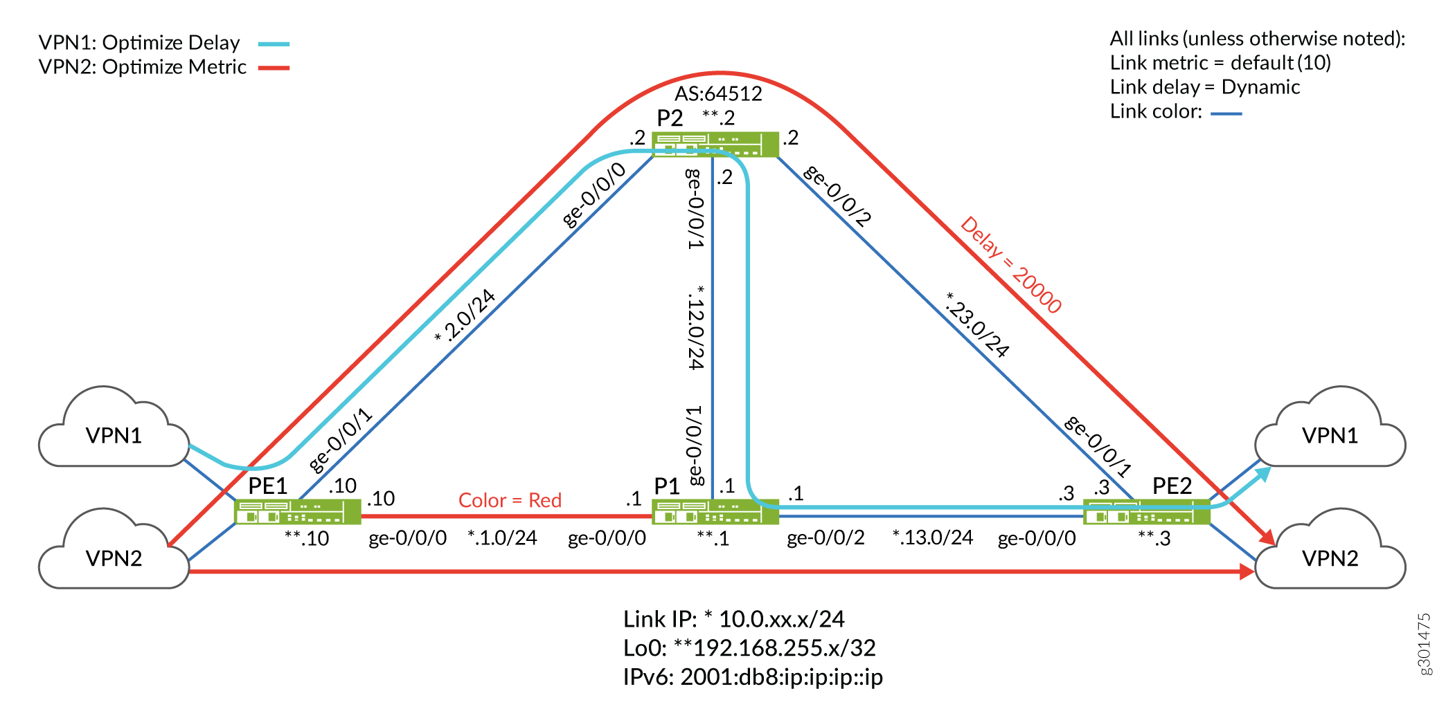
In the topology, most links have a (default) IGP metric of 10, dynamic delay measurements, and blue coloring. The exceptions are the red colored path between PE1 and P1 and the static delay configuration on the P2 to PE2 link.
We've configured the test topology to support IS-IS link delay for both IPv4 and IPv6. We've configured the P2 router as a route reflector with the PE devices as its clients. To keep the topology simple, we are using static routes in the PE2 router's VRFs. This eliminates the need for CE devices and a PE-CE routing protocol such as EBGP.
Your goal is to configure the network so that the routes advertised by PE2 for VPN1 take a path that optimizes delay while also being confined to using only blue links. In contrast, traffic sent to the routes associated with VPN2 can take either a blue or red link with path optimization based on its IGP metric.
- The Flex Algorithm Definition (FAD) for VPN1 uses algorithm 128. We've configured it to use blue colored links only (PE1>P2>P1>PE2) over a path that is optimized to reduce delay. To help demonstrate proper path selection, you configure a static delay of 20000 microseconds between P2 and PE2. This delay is significantly higher than the dynamic delay measured on the remaining links. As a result you expect flex algorithm 128 traffic to avoid the P2 to PE2 link, instead preferring additional hops along the blue color path (PE1>P2>P1>PE2).
- The Flex Algorithm Definition (FAD) for VPN2 uses algorithm 129. We've configured it to take either blue or red links (PE1>P1>PE2 or PE1>P2>PE2), with the path optimized on IGP metric. As a result traffic using flex algorithm 129 has two equal cost paths between PE1 and PE2, both incurring two hops and a resulting metric of 20.
Overview
In IP networks, the bulk of traffic often goes through the core network, which reduces costs but might result in increased latency. Business traffic, however, often benefits from the ability to make path-selection decisions based on other performance metrics, such as path latency, rather than relaying on the traditional path optimization based simply on IGP metrics. Optimizing a path to reduce latency can greatly benefit applications like real-time voice and video. It can also enable high performance access to financial market data where milliseconds can translate into significant gains or losses.
Starting in Junos OS Release 21.1R1, you can enable IS-IS link delay in IP networks. You can achieve minimum IGP metric paths by configuring IS-IS with the appropriate link cost using the default IS-IS algorithm (0). Doing so optimizes paths to the endpoint that are based strictly on the sum of the link metrics. By using the IS-IS delay flex algorithm you can optimize paths based on their end-to-end delay.
Link delay can be dynamically measured using Two-Way Active Measurement Probes (TWAMP). The routers then flood their link delay parameters. The routers in the area store these parameters in the shared Link State Database (LSDB). Ingress nodes run an SPF algorithm against the LSDB to compute paths that are optimized on various attributes, such as link colors, IGP metric, traffic-engineering (TE) metric, or as shown in this example, link delay.
The egress router signals which flex algorithm is desired by attaching an associated color community to routes advertised through BGP. At the sending end (the local PE that has received the tagged routes advertised by the remote PE), these color communities are used to index into a color table that resolves the remote protocol next hop (the PE's loopback address) to a flex algorithm identifier. In the context of Layer 3 VPNs a color mapping policy is used at the ingress node to select which prefixes should have their next hops resolved via the color table.
The local PE then uses its local Flex Algorithm Definition (FAD) to map the flex algorithm identifier into a set of path selection criteria, for example "use blue links and optimize on delay". The ingress PE calculates the optimal path based on the values in the LSDB, pushes the related MPLS label stack onto the packet, and sends it to the associated next hop. This results in traffic-engineered MPLS paths using IS-IS as the signaling protocol.
Configuration
CLI Quick Configuration
To quickly configure this example, copy the following commands, paste them into a text file, remove any line breaks, change any details necessary to match your network configuration, and then copy and paste the commands into the CLI at the [edit] hierarchy level.
Depending on the type of MPCs in your MX Series routers you might need to
explicitly enable enhanced IP services to support the IS-IS delay feature.
When you commit the set chassis network-services
enhanced-ip configuration statement, you will be prompted to
reboot the system.
PE1
set system host-name PE1
set chassis network-services enhanced-ip
set services rpm twamp server authentication-mode none
set services rpm twamp server light
set interfaces ge-0/0/0 description To_R1
set interfaces ge-0/0/0 unit 0 family inet address 10.0.1.10/24
set interfaces ge-0/0/0 unit 0 family iso
set interfaces ge-0/0/0 unit 0 family inet6 address 2001:db8:10:0:1::10/80
set interfaces ge-0/0/0 unit 0 family mpls maximum-labels 16
set interfaces ge-0/0/1 description To_R2
set interfaces ge-0/0/1 unit 0 family inet address 10.0.2.10/24
set interfaces ge-0/0/1 unit 0 family iso
set interfaces ge-0/0/1 unit 0 family inet6 address 2001:db8:10:0:2::10/80
set interfaces ge-0/0/1 unit 0 family mpls maximum-labels 16
set interfaces lo0 unit 0 family inet address 192.168.255.10/32
set interfaces lo0 unit 0 family inet address 127.0.0.1/32
set interfaces lo0 unit 0 family iso address 49.0001.000a.0a0a.0a00
set interfaces lo0 unit 0 family inet6 address 2001:db8:192:168:255::10/128
set interfaces lo0 unit 1 family inet address 172.16.10.1/32
set interfaces lo0 unit 1 family inet6 address 2001:db8:172:16:10::1/128
set interfaces lo0 unit 2 family inet address 172.16.10.2/32
set interfaces lo0 unit 2 family inet6 address 2001:db8:172:16:10::2/128
set policy-options policy-statement pplb then load-balance per-packet
set policy-options policy-statement prefix-sid term 1 from route-filter 192.168.255.10/32 exact
set policy-options policy-statement prefix-sid term 1 then prefix-segment algorithm 128 index 1280
set policy-options policy-statement prefix-sid term 1 then prefix-segment algorithm 128 node-segment
set policy-options policy-statement prefix-sid term 1 then prefix-segment algorithm 129 index 1290
set policy-options policy-statement prefix-sid term 1 then prefix-segment algorithm 129 node-segment
set policy-options policy-statement prefix-sid term 1 then prefix-segment index 1000
set policy-options policy-statement prefix-sid term 1 then prefix-segment node-segment
set policy-options policy-statement prefix-sid term 1 then accept
set policy-options policy-statement prefix-sid term 2 from route-filter 2001:db8:192:168:255::10/128 exact
set policy-options policy-statement prefix-sid term 2 then prefix-segment algorithm 128 index 4280
set policy-options policy-statement prefix-sid term 2 then prefix-segment algorithm 128 node-segment
set policy-options policy-statement prefix-sid term 2 then prefix-segment algorithm 129 index 4290
set policy-options policy-statement prefix-sid term 2 then prefix-segment algorithm 129 node-segment
set policy-options policy-statement prefix-sid term 2 then prefix-segment index 4000
set policy-options policy-statement prefix-sid term 2 then prefix-segment node-segment
set policy-options policy-statement prefix-sid term 2 then accept
set policy-options policy-statement v6vpn1_res_map1 from route-filter 2001:db8:172:16:1::/80 orlonger
set policy-options policy-statement v6vpn1_res_map1 then accept
set policy-options policy-statement v6vpn1_res_map1 then resolution-map map1
set policy-options policy-statement v6vpn2_res_map1 from route-filter 2001:db8:172:16:2::/80 orlonger
set policy-options policy-statement v6vpn2_res_map1 then accept
set policy-options policy-statement v6vpn2_res_map1 then resolution-map map1
set policy-options policy-statement vpn1_res_map1 term 1 from route-filter 172.16.1.0/24 orlonger
set policy-options policy-statement vpn1_res_map1 term 1 then accept
set policy-options policy-statement vpn1_res_map1 term 1 then resolution-map map1
set policy-options policy-statement vpn2_res_map1 term 1 from route-filter 172.16.2.0/24 orlonger
set policy-options policy-statement vpn2_res_map1 term 1 then accept
set policy-options policy-statement vpn2_res_map1 term 1 then resolution-map map1
set policy-options resolution-map map1 mode ip-color
set routing-instances vpn1 instance-type vrf
set routing-instances vpn1 interface lo0.1
set routing-instances vpn1 route-distinguisher 64512:1
set routing-instances vpn1 vrf-target target:64512:1
set routing-instances vpn1 vrf-table-label
set routing-instances vpn2 instance-type vrf
set routing-instances vpn2 interface lo0.2
set routing-instances vpn2 route-distinguisher 64512:2
set routing-instances vpn2 vrf-target target:64512:2
set routing-instances vpn2 vrf-table-label
set protocols bgp group to-RRv6 type internal
set protocols bgp group to-RRv6 local-address 2001:db8:192:168:255::10
set protocols bgp group to-RRv6 import v6vpn1_res_map1
set protocols bgp group to-RRv6 import v6vpn2_res_map1
set protocols bgp group to-RRv6 family inet6 unicast extended-nexthop-color
set protocols bgp group to-RRv6 family inet6-vpn unicast
set protocols bgp group to-RRv6 neighbor 2001:db8:192:168:255::2
set protocols bgp group to-RR type internal
set protocols bgp group to-RR local-address 192.168.255.10
set protocols bgp group to-RR import vpn1_res_map1
set protocols bgp group to-RR import vpn2_res_map1
set protocols bgp group to-RR family inet unicast extended-nexthop-color
set protocols bgp group to-RR family inet-vpn unicast
set protocols bgp group to-RR family traffic-engineering unicast
set protocols bgp group to-RR neighbor 192.168.255.2
set protocols bgp group to-RR vpn-apply-export
set protocols isis interface ge-0/0/0.0 level 2 post-convergence-lfa node-protection
set protocols isis interface ge-0/0/0.0 delay-measurement advertisement periodic threshold 100
set protocols isis interface ge-0/0/0.0 point-to-point
set protocols isis interface ge-0/0/1.0 level 2 post-convergence-lfa node-protection
set protocols isis interface ge-0/0/1.0 delay-measurement advertisement periodic threshold 100
set protocols isis interface ge-0/0/1.0 point-to-point
set protocols isis interface lo0.0 passive
set protocols isis source-packet-routing srgb start-label 80000
set protocols isis source-packet-routing srgb index-range 5000
set protocols isis source-packet-routing flex-algorithm 128
set protocols isis source-packet-routing flex-algorithm 129
set protocols isis level 1 disable
set protocols isis backup-spf-options use-post-convergence-lfa maximum-backup-paths 8
set protocols isis backup-spf-options use-source-packet-routing
set protocols isis traffic-engineering l3-unicast-topology
set protocols isis traffic-engineering advertisement always
set protocols isis export prefix-sid
set protocols mpls traffic-engineering
set protocols mpls admin-groups RED 0
set protocols mpls admin-groups BLUE 1
set protocols mpls icmp-tunneling
set protocols mpls interface all
set protocols mpls interface fxp0.0 disable
set protocols mpls interface ge-0/0/0.0 admin-group RED
set protocols mpls interface ge-0/0/1.0 admin-group BLUE
set routing-options flex-algorithm 128 definition metric-type delay-metric
set routing-options flex-algorithm 128 definition spf
set routing-options flex-algorithm 128 definition admin-group include-any BLUE
set routing-options flex-algorithm 129 definition metric-type igp-metric
set routing-options flex-algorithm 129 definition spf
set routing-options flex-algorithm 129 definition admin-group include-any RED
set routing-options flex-algorithm 129 definition admin-group include-any BLUE
set routing-options router-id 192.168.255.10
set routing-options autonomous-system 64512
set routing-options forwarding-table export pplb
set routing-options forwarding-table ecmp-fast-reroute
set routing-options forwarding-table chained-composite-next-hop ingress l3vpn
P1
set system host-name P1
set chassis network-services enhanced-ip
set services rpm twamp server authentication-mode none
set services rpm twamp server light
set interfaces ge-0/0/0 description To_R0
set interfaces ge-0/0/0 unit 0 family inet address 10.0.1.1/24
set interfaces ge-0/0/0 unit 0 family iso
set interfaces ge-0/0/0 unit 0 family inet6 address 2001:db8:10:0:1::1/80
set interfaces ge-0/0/0 unit 0 family mpls maximum-labels 16
set interfaces ge-0/0/1 description To_R2
set interfaces ge-0/0/1 unit 0 family inet address 10.0.12.1/24
set interfaces ge-0/0/1 unit 0 family iso
set interfaces ge-0/0/1 unit 0 family inet6 address 2001:db8:10:0:12::1/80
set interfaces ge-0/0/1 unit 0 family mpls maximum-labels 16
set interfaces ge-0/0/2 description To_R3
set interfaces ge-0/0/2 unit 0 family inet address 10.0.13.1/24
set interfaces ge-0/0/2 unit 0 family iso
set interfaces ge-0/0/2 unit 0 family inet6 address 2001:db8:10:0:13::1/80
set interfaces ge-0/0/2 unit 0 family mpls maximum-labels 16
set interfaces lo0 unit 0 family inet address 192.168.255.1/32
set interfaces lo0 unit 0 family iso address 49.0001.0005.0505.0500
set interfaces lo0 unit 0 family inet6 address 2001:db8:192:168:255::1/128
set policy-options policy-statement pplb then load-balance per-packet
set policy-options policy-statement prefix-sid term 1 from route-filter 192.168.255.1/32 exact
set policy-options policy-statement prefix-sid term 1 then prefix-segment algorithm 128 index 1281
set policy-options policy-statement prefix-sid term 1 then prefix-segment algorithm 128 node-segment
set policy-options policy-statement prefix-sid term 1 then prefix-segment algorithm 129 index 1291
set policy-options policy-statement prefix-sid term 1 then prefix-segment algorithm 129 node-segment
set policy-options policy-statement prefix-sid term 1 then prefix-segment index 1001
set policy-options policy-statement prefix-sid term 1 then prefix-segment node-segment
set policy-options policy-statement prefix-sid term 1 then accept
set policy-options policy-statement prefix-sid term 2 from route-filter 2001:db8:192:168:255::1/128 exact
set policy-options policy-statement prefix-sid term 2 then prefix-segment algorithm 128 index 4281
set policy-options policy-statement prefix-sid term 2 then prefix-segment algorithm 128 node-segment
set policy-options policy-statement prefix-sid term 2 then prefix-segment algorithm 129 index 4291
set policy-options policy-statement prefix-sid term 2 then prefix-segment algorithm 129 node-segment
set policy-options policy-statement prefix-sid term 2 then prefix-segment index 4001
set policy-options policy-statement prefix-sid term 2 then prefix-segment node-segment
set policy-options policy-statement prefix-sid term 2 then accept
set protocols isis interface ge-0/0/0.0 level 2 post-convergence-lfa node-protection
set protocols isis interface ge-0/0/0.0 delay-measurement advertisement periodic threshold 100
set protocols isis interface ge-0/0/0.0 point-to-point
set protocols isis interface ge-0/0/1.0 level 2 post-convergence-lfa node-protection
set protocols isis interface ge-0/0/1.0 delay-measurement advertisement periodic threshold 100
set protocols isis interface ge-0/0/1.0 point-to-point
set protocols isis interface ge-0/0/2.0 level 2 post-convergence-lfa node-protection
set protocols isis interface ge-0/0/2.0 delay-measurement advertisement periodic threshold 100
set protocols isis interface ge-0/0/2.0 point-to-point
set protocols isis interface lo0.0 passive
set protocols isis source-packet-routing srgb start-label 80000
set protocols isis source-packet-routing srgb index-range 5000
set protocols isis source-packet-routing flex-algorithm 128
set protocols isis source-packet-routing flex-algorithm 129
set protocols isis level 1 disable
set protocols isis backup-spf-options use-post-convergence-lfa maximum-backup-paths 8
set protocols isis backup-spf-options use-source-packet-routing
set protocols isis traffic-engineering l3-unicast-topology
set protocols isis traffic-engineering advertisement always
set protocols isis export prefix-sid
set protocols mpls admin-groups RED 0
set protocols mpls admin-groups BLUE 1
set protocols mpls icmp-tunneling       set protocols mpls interface all
set protocols mpls interface fxp0.0 disable
set protocols mpls interface ge-0/0/0.0 admin-group RED
set protocols mpls interface ge-0/0/1.0 admin-group BLUE
set protocols mpls interface ge-0/0/2.0 admin-group BLUE
set routing-options router-id 192.168.255.1
set routing-options autonomous-system 65412
set routing-options forwarding-table export pplb
P2
set system host-name P2
set chassis network-services enhanced-ip
set services rpm twamp server authentication-mode none
set services rpm twamp server light
set interfaces ge-0/0/0 unit 0 family inet address 10.0.2.2/24
set interfaces ge-0/0/0 unit 0 family iso
set interfaces ge-0/0/0 unit 0 family inet6 address 2001:db8:10:0:2::2/80
set interfaces ge-0/0/0 unit 0 family mpls maximum-labels 16
set interfaces ge-0/0/1 description To_R1
set interfaces ge-0/0/1 unit 0 family inet address 10.0.12.2/24
set interfaces ge-0/0/1 unit 0 family iso
set interfaces ge-0/0/1 unit 0 family inet6 address 2001:db8:10:0:12::2/80
set interfaces ge-0/0/1 unit 0 family mpls maximum-labels 16
set interfaces ge-0/0/2 description To_R3
set interfaces ge-0/0/2 unit 0 family inet address 10.0.23.2/24
set interfaces ge-0/0/2 unit 0 family iso
set interfaces ge-0/0/2 unit 0 family inet6 address 2001:db8:10:0:23::2/80
set interfaces ge-0/0/2 unit 0 family mpls maximum-labels 16
set interfaces lo0 unit 0 family inet address 192.168.255.2/32
set interfaces lo0 unit 0 family iso address 49.0001.0002.0202.0200
set interfaces lo0 unit 0 family inet6 address 2001:db8:192:168:255::2/128
set policy-options policy-statement pplb then load-balance per-packet
set policy-options policy-statement prefix-sid term 1 from route-filter 192.168.255.2/32 exact
set policy-options policy-statement prefix-sid term 1 then prefix-segment algorithm 128 index 1282
set policy-options policy-statement prefix-sid term 1 then prefix-segment algorithm 128 node-segment
set policy-options policy-statement prefix-sid term 1 then prefix-segment algorithm 129 index 1292
set policy-options policy-statement prefix-sid term 1 then prefix-segment algorithm 129 node-segment
set policy-options policy-statement prefix-sid term 1 then prefix-segment index 1002
set policy-options policy-statement prefix-sid term 1 then prefix-segment node-segment
set policy-options policy-statement prefix-sid term 1 then accept
set policy-options policy-statement prefix-sid term 2 from route-filter 2001:db8:192:168:255::2/128 exact
set policy-options policy-statement prefix-sid term 2 then prefix-segment algorithm 128 index 4282
set policy-options policy-statement prefix-sid term 2 then prefix-segment algorithm 128 node-segment
set policy-options policy-statement prefix-sid term 2 then prefix-segment algorithm 129 index 4292
set policy-options policy-statement prefix-sid term 2 then prefix-segment algorithm 129 node-segment
set policy-options policy-statement prefix-sid term 2 then prefix-segment index 4002
set policy-options policy-statement prefix-sid term 2 then prefix-segment node-segment
set policy-options policy-statement prefix-sid term 2 then accept
set policy-options policy-statement ted2nlri_igp term 1 from family traffic-engineering
set policy-options policy-statement ted2nlri_igp term 1 from protocol isis
set policy-options policy-statement ted2nlri_igp term 1 then accept
set protocols bgp group to-RRv6 type internal
set protocols bgp group to-RRv6 local-address 2001:db8:192:168:255::2
set protocols bgp group to-RRv6 family inet6 unicast
set protocols bgp group to-RRv6 family inet6-vpn unicast
set protocols bgp group to-RRv6 neighbor 2001:db8:192:168:255::10
set protocols bgp group to-RRv6 neighbor 2001:db8:192:168:255::3
set protocols bgp group to-RR type internal
set protocols bgp group to-RR local-address 192.168.255.2
set protocols bgp group to-RR family inet unicast
set protocols bgp group to-RR family inet-vpn unicast
set protocols bgp group to-RR neighbor 192.168.255.10
set protocols bgp group to-RR neighbor 192.168.255.3
set protocols bgp cluster 192.168.255.2
set protocols isis interface ge-0/0/0.0 level 2 post-convergence-lfa node-protection
set protocols isis interface ge-0/0/0.0 delay-measurement advertisement periodic threshold 100
set protocols isis interface ge-0/0/0.0 point-to-point
set protocols isis interface ge-0/0/1.0 level 2 post-convergence-lfa node-protection
set protocols isis interface ge-0/0/1.0 delay-measurement advertisement periodic threshold 100
set protocols isis interface ge-0/0/1.0 point-to-point
set protocols isis interface ge-0/0/2.0 level 2 post-convergence-lfa node-protection
set protocols isis interface ge-0/0/2.0 delay-metric 20000
set protocols isis interface ge-0/0/2.0 delay-measurement advertisement periodic threshold 100
set protocols isis interface ge-0/0/2.0 point-to-point
set protocols isis interface lo0.0 passive
set protocols isis source-packet-routing srgb start-label 80000
set protocols isis source-packet-routing srgb index-range 5000
set protocols isis source-packet-routing flex-algorithm 128
set protocols isis source-packet-routing flex-algorithm 129
set protocols isis level 1 disable
set protocols isis backup-spf-options use-post-convergence-lfa maximum-backup-paths 8
set protocols isis backup-spf-options use-source-packet-routing
set protocols isis traffic-engineering l3-unicast-topology
set protocols isis traffic-engineering advertisement always
set protocols isis export prefix-sid
set protocols mpls traffic-engineering
set protocols mpls admin-groups RED 0
set protocols mpls admin-groups BLUE 1
set protocols mpls icmp-tunneling       set protocols mpls interface all
set protocols mpls interface fxp0.0 disable
set protocols mpls interface ge-0/0/0.0 admin-group BLUE
set protocols mpls interface ge-0/0/1.0 admin-group BLUE
set protocols mpls interface ge-0/0/2.0 admin-group BLUE
set routing-options router-id 192.168.255.2
set routing-options autonomous-system 64512
set routing-options forwarding-table export pplb
PE2
set system host-name PE2
set chassis network-services enhanced-ip
set services rpm twamp server authentication-mode none
set services rpm twamp server light
set interfaces ge-0/0/0 description To_R1
set interfaces ge-0/0/0 unit 0 family inet address 10.0.13.3/24
set interfaces ge-0/0/0 unit 0 family iso
set interfaces ge-0/0/0 unit 0 family inet6 address 2001:db8:10:0:13::3/80
set interfaces ge-0/0/0 unit 0 family mpls maximum-labels 16
set interfaces ge-0/0/1 description To_R2
set interfaces ge-0/0/1 unit 0 family inet address 10.0.23.3/24
set interfaces ge-0/0/1 unit 0 family iso
set interfaces ge-0/0/1 unit 0 family inet6 address 2001:db8:10:0:23::364/128
set interfaces ge-0/0/1 unit 0 family mpls maximum-labels 16
set interfaces lo0 unit 0 family inet address 192.168.255.3/32
set interfaces lo0 unit 0 family inet address 127.0.0.1/32
set interfaces lo0 unit 0 family iso address 49.0001.0007.0707.0700
set interfaces lo0 unit 0 family inet6 address 2001:db8:192:168:255::3/128
set interfaces lo0 unit 1 family inet address 172.16.3.1/32
set interfaces lo0 unit 1 family inet6 address 2001:db8:172:16:3::1/128
set interfaces lo0 unit 2 family inet address 172.16.3.2/32
set interfaces lo0 unit 2 family inet6 address 2001:db8:172:16:3::2/128
set policy-options policy-statement pplb then load-balance per-packet
set policy-options policy-statement prefix-sid term 1 from route-filter 192.168.255.3/32 exact
set policy-options policy-statement prefix-sid term 1 then prefix-segment algorithm 128 index 1283
set policy-options policy-statement prefix-sid term 1 then prefix-segment algorithm 128 node-segment
set policy-options policy-statement prefix-sid term 1 then prefix-segment algorithm 129 index 1293
set policy-options policy-statement prefix-sid term 1 then prefix-segment algorithm 129 node-segment
set policy-options policy-statement prefix-sid term 1 then prefix-segment index 1003
set policy-options policy-statement prefix-sid term 1 then prefix-segment node-segment
set policy-options policy-statement prefix-sid term 1 then accept
set policy-options policy-statement prefix-sid term 2 from route-filter 2001:db8:192:168:255::3/128 exact
set policy-options policy-statement prefix-sid term 2 then prefix-segment algorithm 128 index 4283
set policy-options policy-statement prefix-sid term 2 then prefix-segment algorithm 128 node-segment
set policy-options policy-statement prefix-sid term 2 then prefix-segment algorithm 129 index 4293
set policy-options policy-statement prefix-sid term 2 then prefix-segment algorithm 129 node-segment
set policy-options policy-statement prefix-sid term 2 then prefix-segment index 4003
set policy-options policy-statement prefix-sid term 2 then prefix-segment node-segment
set policy-options policy-statement prefix-sid term 2 then accept
set policy-options policy-statement vpn_1_export term 1 from route-filter 172.16.1.0/24 orlonger
set policy-options policy-statement vpn_1_export term 1 then community add color128
set policy-options policy-statement vpn_1_export term 1 then next-hop 192.168.255.3
set policy-options policy-statement vpn_1_export term 1 then accept
set policy-options policy-statement vpn_1_export_v6 term 1 from route-filter 2001:db8:172:16:1::/80 orlonger
set policy-options policy-statement vpn_1_export_v6 term 1 then community add color128
set policy-options policy-statement vpn_1_export_v6 term 1 then next-hop 2001:db8:192:168:255::3
set policy-options policy-statement vpn_1_export_v6 term 1 then accept
set policy-options policy-statement vpn_1_export_v6 term 2 from route-filter 2001:db8:172:16:3::1/128 exact
set policy-options policy-statement vpn_1_export_v6 term 2 then community add color128
set policy-options policy-statement vpn_1_export_v6 term 2 then next-hop 2001:db8:192:168:255::3
set policy-options policy-statement vpn_1_export_v6 term 2 then accept
set policy-options policy-statement vpn_2_export term 1 from route-filter 172.16.2.0/24 orlonger
set policy-options policy-statement vpn_2_export term 1 then community add color129
set policy-options policy-statement vpn_2_export term 1 then next-hop 192.168.255.3
set policy-options policy-statement vpn_2_export term 1 then accept
set policy-options policy-statement vpn_2_export_v6 term 1 from route-filter 2001:db8:172:16:2::/80 orlonger
set policy-options policy-statement vpn_2_export_v6 term 1 then community add color129
set policy-options policy-statement vpn_2_export_v6 term 1 then next-hop 2001:db8:192:168:255::3
set policy-options policy-statement vpn_2_export_v6 term 1 then accept
set policy-options community color128 members color:0:128
set policy-options community color129 members color:0:129
set policy-options resolution-map map1 mode ip-color
set routing-instances vpn1 instance-type vrf
set routing-instances vpn1 routing-options rib vpn1.inet6.0 static route 2001:db8:172:16:1::/80 receive
set routing-instances vpn1 routing-options static route 172.16.1.0/24 receive
set routing-instances vpn1 interface lo0.1
set routing-instances vpn1 route-distinguisher 64512:1
set routing-instances vpn1 vrf-target target:64512:1
set routing-instances vpn1 vrf-table-label
set routing-instances vpn2 instance-type vrf
set routing-instances vpn2 routing-options rib vpn2.inet6.0 static route 2001:db8:172:16:2::/80 receive
set routing-instances vpn2 routing-options static route 172.16.2.0/24 receive
set routing-instances vpn2 interface lo0.2
set routing-instances vpn2 route-distinguisher 64512:2
set routing-instances vpn2 vrf-target target:64512:2
set routing-instances vpn2 vrf-table-label
set protocols bgp group to-RRv6 type internal
set protocols bgp group to-RRv6 local-address 2001:db8:192:168:255::3
set protocols bgp group to-RRv6 family inet6 unicast extended-nexthop-color
set protocols bgp group to-RRv6 family inet6-vpn unicast
set protocols bgp group to-RRv6 export vpn_1_export_v6
set protocols bgp group to-RRv6 export vpn_2_export_v6
set protocols bgp group to-RRv6 neighbor 2001:db8:192:168:255::2
set protocols bgp group to-RRv6 vpn-apply-export
set protocols bgp group to-RR type internal
set protocols bgp group to-RR local-address 192.168.255.3
set protocols bgp group to-RR family inet unicast extended-nexthop-color
set protocols bgp group to-RR family inet-vpn unicast
set protocols bgp group to-RR export vpn_1_export
set protocols bgp group to-RR export vpn_2_export
set protocols bgp group to-RR neighbor 192.168.255.2
set protocols bgp group to-RR vpn-apply-export
set protocols isis interface ge-0/0/0.0 level 2 post-convergence-lfa node-protection
set protocols isis interface ge-0/0/0.0 delay-measurement advertisement periodic threshold 100
set protocols isis interface ge-0/0/0.0 point-to-point
set protocols isis interface ge-0/0/1.0 level 2 post-convergence-lfa node-protection
set protocols isis interface ge-0/0/1.0 delay-measurement advertisement periodic threshold 100
set protocols isis interface ge-0/0/1.0 point-to-point
set protocols isis interface ge-0/0/2.0 delay-metric 20000
set protocols isis interface lo0.0 passive
set protocols isis source-packet-routing srgb start-label 80000
set protocols isis source-packet-routing srgb index-range 5000
set protocols isis source-packet-routing flex-algorithm 128
set protocols isis source-packet-routing flex-algorithm 129
set protocols isis level 1 disable
set protocols isis backup-spf-options use-post-convergence-lfa maximum-backup-paths 8
set protocols isis backup-spf-options use-source-packet-routing
set protocols isis traffic-engineering l3-unicast-topology
set protocols isis traffic-engineering advertisement always
set protocols isis export prefix-sid
set protocols mpls admin-groups RED 0
set protocols mpls admin-groups BLUE 1
set protocols mpls icmp-tunneling       set protocols mpls interface all
set protocols mpls interface fxp0.0 disable
set protocols mpls interface ge-0/0/0.0 admin-group BLUE
set protocols mpls interface ge-0/0/1.0 admin-group BLUEset routing-options router-id 192.168.255.3
set routing-options autonomous-system 64512
set routing-options forwarding-table export pplb
set routing-options forwarding-table ecmp-fast-reroute
set routing-options forwarding-table chained-composite-next-hop ingress l3vpn
Step-by-step Procedure
-
Configure the basic device settings such as hostname, IPv4, IPv6 addresses, loopback interface addresses,
enhanced-ipmode, and enable the ISO and MPLS protocol families on all interfaces of all 4 routers.user@PE1# set system host-name PE1 set chassis network-services enhanced-ip set interfaces ge-0/0/0 description To_R1 set interfaces ge-0/0/0 unit 0 family inet address 10.0.1.10/24 set interfaces ge-0/0/0 unit 0 family iso set interfaces ge-0/0/0 unit 0 family inet6 address 2001:db8:10:0:1::10/80 set interfaces ge-0/0/0 unit 0 family mpls maximum-labels 16 set interfaces ge-0/0/1 description To_R2 set interfaces ge-0/0/1 unit 0 family inet address 10.0.2.10/24 set interfaces ge-0/0/1 unit 0 family iso set interfaces ge-0/0/1 unit 0 family inet6 address 2001:db8:10:0:2::10/80 set interfaces ge-0/0/1 unit 0 family mpls maximum-labels 16 set interfaces lo0 unit 0 family inet address 192.168.255.10/32 set interfaces lo0 unit 0 family inet address 127.0.0.1/32 set interfaces lo0 unit 0 family iso address 49.0001.000a.0a0a.0a00 set interfaces lo0 unit 0 family inet6 address 2001:db8:192:168:255::10/128 set interfaces lo0 unit 1 family inet address 172.16.10.1/32 set interfaces lo0 unit 1 family inet6 address 2001:db8:172:16:10::1/128 set interfaces lo0 unit 2 family inet address 172.16.10.2/32 set interfaces lo0 unit 2 family inet6 address 2001:db8:172:16:10::2/128
-
Configure the router-ID, autonomous system (AS) number, and apply a load balancing export policy to the forwarding table on all routers to enable load balancing of traffic.
user@PE1#
set routing-options router-id 192.168.255.10
set routing-options autonomous-system 64512
set routing-options forwarding-table export pplb
-
On PE1 and PE2, configure equal-cost multipath (ECMP) to enable fast reroute protection. Also configure chained composite next hop to allow the routers to point routes that share the same destination to a common forwarding next hop. This option improves forwarding information base (FIB) scaling.
user@PE1#
set routing-options forwarding-table ecmp-fast-reroute
set routing-options forwarding-table chained-composite-next-hop ingress l3vpn
-
Enable MPLS protocol processing on all interfaces at all routers. Also enable traffic engineering.
user@PE1#
set protocols mpls interface fxp0.0 disable
set protocols mpls interface all
set protocols mpls traffic-engineering
-
Enable TWAMP probes on all routers. These probes support dynamic measurement of the link delay between each pair of routers.
user@PE1#
set services rpm twamp server authentication-mode none
set services rpm twamp server light
-
Configure the IS-IS protocol for point-to-point operation (TWAMP based delay measurements are not supported on multi-point links), and enable node protection mode for Topology-Independent Loop-Free Alternate (TILFA) operation on all interfaces. You also enable passive mode IS-IS on the loopback interface and disable IS-IS level 1 to use only IS-IS level 2. Enable traffic engineering with layer 3 unicast topology to download IGP topology into the TED. Configure IS-IS to support SPRING routed paths. The prefix-sid export policy is defined in a subsequent step. This policy is used to have the local node advertise its loopback address with a mapping to one ore more flex algorithms.
user@PE1#
set protocols isis level 1 disable
set protocols isis interface ge-0/0/0.0 point-to-point
set protocols isis interface ge-0/0/0.0 level 2 post-convergence-lfa node-protection
set protocols isis interface ge-0/0/1.0 point-to-point
set protocols isis interface ge-0/0/1.0 level 2 post-convergence-lfa node-protection
set protocols isis interface lo0.0 passive
set protocols isis backup-spf-options use-post-convergence-lfa maximum-backup-paths 8
set protocols isis backup-spf-options use-source-packet-routing
set protocols isis traffic-engineering l3-unicast-topology
set protocols isis traffic-engineering advertisement always
set protocols isis export prefix-sid
-
Configure dynamic IS-IS link delay-measurement using TWAMP probes on all IS-IS interfaces at all routers (except for the link between P2 and PE2, which uses a static delay value in this example).
user@PE1#
set protocols isis interface ge-0/0/0.0 delay-measurement advertisement periodic threshold 100
set protocols isis interface ge-0/0/1.0 delay-measurement advertisement periodic threshold 100
user@P1#
set protocols isis interface ge-0/0/0.0 delay-measurement advertisement periodic threshold 100
set protocols isis interface ge-0/0/1.0 delay-measurement advertisement periodic threshold 100
set protocols isis interface ge-0/0/2.0 delay-measurement advertisement periodic threshold 100
user@P2#
set protocols isis interface ge-0/0/0.0 delay-measurement advertisement periodic threshold 100
set protocols isis interface ge-0/0/1.0 delay-measurement advertisement periodic threshold 100
set protocols isis interface ge-0/0/2.0 delay-measurement advertisement periodic threshold 100
user@PE2#
set protocols isis interface ge-0/0/0.0 delay-measurement advertisement periodic threshold 100
set protocols isis interface ge-0/0/1.0 delay-measurement advertisement periodic threshold 100
-
Configure the static delay-metric on the link between P2 and PE2.
user@P2#
set protocols isis interface ge-0/0/2.0 delay-metric 20000
user@PE2#
set protocols isis interface ge-0/0/1.0 delay-metric 20000
-
Configure PE1 and PE2 to support two Layer 3 VPNs (VPN1 and VPN2).
user@PE1#
set routing-instances vpn1 instance-type vrf
set routing-instances vpn1 interface lo0.1
set routing-instances vpn1 route-distinguisher 64512:1
set routing-instances vpn1 vrf-target target:64512:1
set routing-instances vpn1 vrf-table-label

set routing-instances vpn2 instance-type vrf
set routing-instances vpn2 interface lo0.2
set routing-instances vpn2 route-distinguisher 64512:2
set routing-instances vpn2 vrf-target target:64512:2
set routing-instances vpn2 vrf-table-label
Note:Note that the routing instances at PE2 are configured with IPv4 and IPv6 static routes. These routes are configured with the
receiveoption to allow you to test connectivity using ping. The IS-IS delay feature operates the same if the Layer 3 VPN uses a dynamic routing protocol between the PE and an attached CE device. We use static routes in this example to keep the topology simple to allow focus on the IS-IS delay optimization feature.user@PE2# set routing-instances vpn1 instance-type vrf set routing-instances vpn1 routing-options rib vpn1.inet6.0 static route 2001:db8:172:16:1::/80 receive set routing-instances vpn1 routing-options static route 172.16.1.0/24 receive set routing-instances vpn1 interface lo0.1 set routing-instances vpn1 route-distinguisher 64512:1 set routing-instances vpn1 vrf-target target:64512:1 set routing-instances vpn1 vrf-table-label set routing-instances vpn2 instance-type vrf set routing-instances vpn2 routing-options rib vpn2.inet6.0 static route 2001:db8:172:16:2::/80 receive set routing-instances vpn2 routing-options static route 172.16.2.0/24 receive set routing-instances vpn2 interface lo0.2 set routing-instances vpn2 route-distinguisher 64512:2 set routing-instances vpn2 vrf-target target:64512:2 set routing-instances vpn2 vrf-table-label
-
Configure a map policy at PE1 to enable VPN route resolution for matching prefixes against the BGP color table. This allows you to evoke flex path forwarding algorithms on a per-prefix basis. The map1 resolution policy is set to the
ip-colorresolution mode.Note:In a Layer 3 VPN context a mapping policy is needed to select which prefixes are allowed to have their next hop resolved in the color table. Simply having routes with extended next hops and color communities attached does not result in the use of the color table, unless a mapping policy is used.
user@PE1#
set policy-options policy-statement vpn1_res_map1 term 1 from route-filter 172.16.1.0/24 orlonger
set policy-options policy-statement vpn1_res_map1 term 1 then accept
set policy-options policy-statement vpn1_res_map1 term 1 then resolution-map map1
set policy-options policy-statement vpn2_res_map1 term 1 from route-filter 172.16.2.0/24 orlonger
set policy-options policy-statement vpn2_res_map1 term 1 then accept
set policy-options policy-statement vpn2_res_map1 term 1 then resolution-map map1
set policy-options policy-statement v6vpn1_res_map1 from route-filter 2001:db8:172:16:1::/80 orlonger
set policy-options policy-statement v6vpn1_res_map1 then accept
set policy-options policy-statement v6vpn1_res_map1 then resolution-map map1
set policy-options policy-statement v6vpn2_res_map1 from route-filter 2001:db8:172:16:2::/80 orlonger
set policy-options policy-statement v6vpn2_res_map1 then accept
set policy-options policy-statement v6vpn2_res_map1 then resolution-map map1
set policy-options resolution-map map1 mode ip-color
-
Configure VPN route export policies at PE2 to attach the desired color communities to the VPN routes it advertises to PE1 (via the route reflector). Of significance here is how the routes from VPN1 have the color community for flex path 128 (optimize delay) attached, while the routes advertised from VPN2 have the 129 color community attached (optimize IGP metric).
user@PE2#
set policy-options policy-statement vpn_1_export term 1 from route-filter 172.16.1.0/24 orlonger
set policy-options policy-statement vpn_1_export term 1 then community add color128
set policy-options policy-statement vpn_1_export term 1 then next-hop 192.168.255.3
set policy-options policy-statement vpn_1_export term 1 then accept

set policy-options policy-statement vpn_2_export term 1 from route-filter 172.16.2.0/24 orlonger
set policy-options policy-statement vpn_2_export term 1 then community add color129
set policy-options policy-statement vpn_2_export term 1 then next-hop 192.168.255.3
set policy-options policy-statement vpn_2_export term 1 then accept

set policy-options policy-statement vpn_1_export_v6 term 1 from route-filter 2001:db8:172:16:1::/80 orlonger
set policy-options policy-statement vpn_1_export_v6 term 1 then community add color128
set policy-options policy-statement vpn_1_export_v6 term 1 then next-hop 2001:db8:192:168:255::3
set policy-options policy-statement vpn_1_export_v6 term 1 then accept
set policy-options policy-statement vpn_2_export_v6 term 1 from route-filter 2001:db8:172:16:2::/80 orlonger
set policy-options policy-statement vpn_2_export_v6 term 1 then community add color129
set policy-options policy-statement vpn_2_export_v6 term 1 then next-hop 2001:db8:192:168:255::3
set policy-options policy-statement vpn_2_export_v6 term 1 then accept

set policy-options community color128 members color:0:128
set policy-options community color129 members color:0:129
-
Configure BGP peering between the PE devices and the route reflector. Configure the unicast network layer reachability information (NLRI) to support extended color next hops on the PE devices. Enabling this option allows routes with color communities to have their next hop resolve through the color table. Without the extended next hop setting route with color communities undergoing normal next hop resolution and will not use flex algorithm paths.
-
You also enable support for IPv4 and IPv6 Layer 3 VPN unicast routes. On PE1 you apply the color mapping policies as import, so it can act on the routes received from the remote PE device.
user@PE1#
set protocols bgp group to-RR type internal
set protocols bgp group to-RR local-address 192.168.255.10
set protocols bgp group to-RR neighbor 192.168.255.2
set protocols bgp group to-RR family inet unicast extended-nexthop-color
set protocols bgp group to-RR family inet-vpn unicast
set protocols bgp group to-RR family traffic-engineering unicast
set protocols bgp group to-RR import vpn1_res_map1
set protocols bgp group to-RR import vpn2_res_map1
set protocols bgp group to-RRv6 type internal
set protocols bgp group to-RRv6 local-address 2001:db8:192:168:255::10
set protocols bgp group to-RRv6 neighbor 2001:db8:192:168:255::2
set protocols bgp group to-RRv6 family inet6 unicast extended-nexthop-color
set protocols bgp group to-RRv6 family inet6-vpn unicast
set protocols bgp group to-RRv6 import v6vpn1_res_map1
set protocols bgp group to-RRv6 import v6vpn2_res_map1
user@P2#
set protocols bgp group to-RR type internal
set protocols bgp group to-RR local-address 192.168.255.2
set protocols bgp group to-RR neighbor 192.168.255.10
set protocols bgp group to-RR neighbor 192.168.255.3
set protocols bgp cluster 192.168.255.2
set protocols bgp group to-RR family inet unicast
set protocols bgp group to-RR family inet-vpn unicast
On PE 2 you apply export policy to attach the desired color community to the VPN route advertisements sent to PE1. The
vpn-apply-exportoption is needed at PE2 to allow the export policies to act on VPN routes advertised to remote PEs.user@PE2# set protocols bgp group to-RR type internal set protocols bgp group to-RR local-address 192.168.255.3 set protocols bgp group to-RR neighbor 192.168.255.2 set protocols bgp group to-RR family inet unicast extended-nexthop-color set protocols bgp group to-RR family inet-vpn unicast set protocols bgp group to-RR export vpn_1_export set protocols bgp group to-RR export vpn_2_export set protocols bgp group to-RR vpn-apply-export set protocols bgp group to-RRv6 type internal set protocols bgp group to-RRv6 local-address 2001:db8:192:168:255::3 set protocols bgp group to-RRv6 neighbor 2001:db8:192:168:255::2 set protocols bgp group to-RRv6 family inet6 unicast extended-nexthop-color set protocols bgp group to-RRv6 family inet6-vpn unicast set protocols bgp group to-RRv6 export vpn_1_export_v6 set protocols bgp group to-RRv6 export vpn_2_export_v6 set protocols bgp group to-RRv6 vpn-apply-export
-
Define the per-packet load balancing policy on all routers.
user@PE1#
set policy-options policy-statement pplb then load-balance per-packet
-
Configure support for segment routing with two flex algorithms (128 and 129) on all routers.
user@PE1#
set protocols isis source-packet-routing srgb start-label 80000
set protocols isis source-packet-routing srgb index-range 5000
set protocols isis source-packet-routing flex-algorithm 128
set protocols isis source-packet-routing flex-algorithm 129
-
Configure all routers to advertise their loopback address with support for both the 128 and 129 flex algorithms. The
prefix-segment
                                index
option sets the base label for each router's loopback address. In this example the IPv4 base index and IPv6 base index is set to reflect the router number. As a result R0 (PE1) uses 1000 for IPv4 while R1 (P1) uses 1001.user@PE1# set policy-options policy-statement prefix-sid term 1 from route-filter 192.168.255.10/32 exact set policy-options policy-statement prefix-sid term 1 then prefix-segment algorithm 128 index 1280 set policy-options policy-statement prefix-sid term 1 then prefix-segment algorithm 128 node-segment set policy-options policy-statement prefix-sid term 1 then prefix-segment algorithm 129 index 1290 set policy-options policy-statement prefix-sid term 1 then prefix-segment algorithm 129 node-segment set policy-options policy-statement prefix-sid term 1 then prefix-segment index 1000 set policy-options policy-statement prefix-sid term 1 then prefix-segment node-segment set policy-options policy-statement prefix-sid term 1 then accept set policy-options policy-statement prefix-sid term 2 from route-filter 2001:db8:192:168:255::10/128 exact set policy-options policy-statement prefix-sid term 2 then prefix-segment algorithm 128 index 4280 set policy-options policy-statement prefix-sid term 2 then prefix-segment algorithm 128 node-segment set policy-options policy-statement prefix-sid term 2 then prefix-segment algorithm 129 index 4290 set policy-options policy-statement prefix-sid term 2 then prefix-segment algorithm 129 node-segment set policy-options policy-statement prefix-sid term 2 then prefix-segment index 4000 set policy-options policy-statement prefix-sid term 2 then prefix-segment node-segment set policy-options policy-statement prefix-sid term 2 then accept
user@P1#
set policy-options policy-statement prefix-sid term 1 from route-filter 192.168.255.1/32 exact
set policy-options policy-statement prefix-sid term 1 then prefix-segment algorithm 128 index 1281
set policy-options policy-statement prefix-sid term 1 then prefix-segment algorithm 128 node-segment
set policy-options policy-statement prefix-sid term 1 then prefix-segment algorithm 129 index 1291
set policy-options policy-statement prefix-sid term 1 then prefix-segment algorithm 129 node-segment
set policy-options policy-statement prefix-sid term 1 then prefix-segment index 1001
set policy-options policy-statement prefix-sid term 1 then prefix-segment node-segment
set policy-options policy-statement prefix-sid term 1 then accept

set policy-options policy-statement prefix-sid term 2 from route-filter 2001:db8:192:168:255::1/128 exact
set policy-options policy-statement prefix-sid term 2 then prefix-segment algorithm 128 index 4281
set policy-options policy-statement prefix-sid term 2 then prefix-segment algorithm 128 node-segment
set policy-options policy-statement prefix-sid term 2 then prefix-segment algorithm 129 index 4291
set policy-options policy-statement prefix-sid term 2 then prefix-segment algorithm 129 node-segment
set policy-options policy-statement prefix-sid term 2 then prefix-segment index 4001
set policy-options policy-statement prefix-sid term 2 then prefix-segment node-segment
set policy-options policy-statement prefix-sid term 2 then accept
user@P2#
set policy-options policy-statement prefix-sid term 1 from route-filter 192.168.255.2/32 exact
set policy-options policy-statement prefix-sid term 1 then prefix-segment algorithm 128 index 1282
set policy-options policy-statement prefix-sid term 1 then prefix-segment algorithm 128 node-segment
set policy-options policy-statement prefix-sid term 1 then prefix-segment algorithm 129 index 1292
set policy-options policy-statement prefix-sid term 1 then prefix-segment algorithm 129 node-segment
set policy-options policy-statement prefix-sid term 1 then prefix-segment index 1002
set policy-options policy-statement prefix-sid term 1 then prefix-segment node-segment
set policy-options policy-statement prefix-sid term 1 then accept

set policy-options policy-statement prefix-sid term 2 from route-filter 2001:db8:192:168:255::2/128 exact
set policy-options policy-statement prefix-sid term 2 then prefix-segment algorithm 128 index 4282
set policy-options policy-statement prefix-sid term 2 then prefix-segment algorithm 128 node-segment
set policy-options policy-statement prefix-sid term 2 then prefix-segment algorithm 129 index 4292
set policy-options policy-statement prefix-sid term 2 then prefix-segment algorithm 129 node-segment
set policy-options policy-statement prefix-sid term 2 then prefix-segment index 4002
set policy-options policy-statement prefix-sid term 2 then prefix-segment node-segment
set policy-options policy-statement prefix-sid term 2 then accept
user@PE2#
set policy-options policy-statement prefix-sid term 1 from route-filter 192.168.255.3/32 exact
set policy-options policy-statement prefix-sid term 1 then prefix-segment algorithm 128 index 1283
set policy-options policy-statement prefix-sid term 1 then prefix-segment algorithm 128 node-segment
set policy-options policy-statement prefix-sid term 1 then prefix-segment algorithm 129 index 1293
set policy-options policy-statement prefix-sid term 1 then prefix-segment algorithm 129 node-segment
set policy-options policy-statement prefix-sid term 1 then prefix-segment index 1003
set policy-options policy-statement prefix-sid term 1 then prefix-segment node-segment
set policy-options policy-statement prefix-sid term 1 then accept

set policy-options policy-statement prefix-sid term 2 from route-filter 2001:db8:192:168:255::3/128 exact
set policy-options policy-statement prefix-sid term 2 then prefix-segment algorithm 128 index 4283
set policy-options policy-statement prefix-sid term 2 then prefix-segment algorithm 128 node-segment
set policy-options policy-statement prefix-sid term 2 then prefix-segment algorithm 129 index 4293
set policy-options policy-statement prefix-sid term 2 then prefix-segment algorithm 129 node-segment
set policy-options policy-statement prefix-sid term 2 then prefix-segment index 4003
set policy-options policy-statement prefix-sid term 2 then prefix-segment node-segment
set policy-options policy-statement prefix-sid term 2 then accept
-
On all routers define the RED and BLUE MPLS administration groups, and assign the desired color to each interface. You also enable ICMP tunneling to allow trace route support in the context of MPLS based Layer 3 VPNs.
user@PE1#
set protocols mpls admin-groups RED 0
set protocols mpls admin-groups BLUE 1
set protocols mpls icmp-tunneling set protocols mpls interface ge-0/0/0.0 admin-group RED
set protocols mpls interface ge-0/0/1.0 admin-group BLUE
user@P1#
set protocols mpls admin-groups RED 0
set protocols mpls admin-groups BLUE 1
set protocols mpls icmp-tunneling       set protocols mpls interface ge-0/0/0.0 admin-group RED
set protocols mpls interface ge-0/0/1.0 admin-group BLUE
set protocols mpls interface ge-0/0/2.0 admin-group BLUE
user@P2#
set protocols mpls admin-groups RED 0
set protocols mpls admin-groups BLUE 1
set protocols mpls icmp-tunneling       set protocols mpls interface ge-0/0/0.0 admin-group BLUE
set protocols mpls interface ge-0/0/1.0 admin-group BLUE
set protocols mpls interface ge-0/0/2.0 admin-group BLUE
user@PE2#
set protocols mpls admin-groups RED 0
set protocols mpls admin-groups BLUE 1
set protocols mpls icmp-tunneling       set protocols mpls interface ge-0/0/0.0 admin-group BLUE
set protocols mpls interface ge-0/0/1.0 admin-group BLUE
-
Configure the FADs at the ingress PE device (PE1) under the
routing-optionshierarchy. In this case you assign flex algorithm 128 to optimize the path based on thedelay-metricand 129 to optimize on theigp-metric. In this example, flex algorithm 128 must take only blue color paths, while flex algorithm 129 can take either a blue or a red color path. In this example you define the FADs at PE1 only as we focus only on the forwarding path from PE1 to PE2.To support bidirectional flex path forwarding you will need to define the desired FADs on the PE2 device. The P routers don't require a FAD definition as the FAD is only used by the ingress node when calculating a path to the egress node.
user@PE1#
set routing-options flex-algorithm 128 definition metric-type delay-metric
set routing-options flex-algorithm 128 definition spf
set routing-options flex-algorithm 128 definition admin-group include-any BLUE

set routing-options flex-algorithm 129 definition metric-type igp-metric
set routing-options flex-algorithm 129 definition spf
set routing-options flex-algorithm 129 definition admin-group include-any RED
set routing-options flex-algorithm 129 definition admin-group include-any BLUE
-
Enter
committo from the configuration mode.
Results
Check the results of the configuration:
user@PE1# show interfaces
ge-0/0/0 {
    description To_R1;
    unit 0 {
        family inet {
            address 10.0.1.10/24;
        }
        family iso;
        family inet6 {
            address 2001:db8:10:0:1::10/80;
        }
        family mpls {
            maximum-labels 16;
        }
    }
}
ge-0/0/1 {
    description To_R2;
    unit 0 {
        family inet {
            address 10.0.2.10/24;
        }
        family iso;
        family inet6 {
            address 2001:db8:10:0:2::10/80;
        }
        family mpls {
            maximum-labels 16;
        }
    }
}
lo0 {
    unit 0 {
        family inet {
            address 192.168.255.10/32;
            address 127.0.0.1/32;
        }
        family iso {
            address 49.0001.000a.0a0a.0a00;
        }
        family inet6 {
            address 2001:db8:192:168:255::10/128;
        }
    }
    unit 1 {
        family inet {
            address 172.16.10.1/32;
        }
        family inet6 {
            address 2001:db8:172:16:10::1/128;
        }
    }
    unit 2 {
        family inet {
            address 172.16.10.2/32;
        }
        family inet6 {
            address 2001:db8:172:16:10::2/128;
        }
    }
}
user@PE1# show policy-options
policy-statement pplb {
    then {
        load-balance per-packet;
    }
}
policy-statement prefix-sid {
    term 1 {
        from {
            route-filter 192.168.255.10/32 exact;
        }
        then {
            prefix-segment {
                algorithm 128 index 1280 node-segment;
                algorithm 129 index 1290 node-segment;
                index 1000;
                node-segment;
            }
            accept;
        }
    }
    term 2 {
        from {
            route-filter 2001:db8:192:168:255::10/128 exact;
        }
        then {
            prefix-segment {
                algorithm 128 index 4280 node-segment;
                algorithm 129 index 4290 node-segment;
                index 4000;
                node-segment;
            }
            accept;
        }
    }
}
policy-statement v6vpn1_res_map1 {
    from {
        route-filter 2001:db8:172:16:1::/80 orlonger;
    }
    then {
        accept;
        resolution-map map1;
    }
}
policy-statement v6vpn2_res_map1 {
    from {
        route-filter 2001:db8:172:16:2::/80 orlonger;
    }
    then {
        accept;
        resolution-map map1;
    }
}
policy-statement vpn1_res_map1 {
    term 1 {
        from {
            route-filter 172.16.1.0/24 orlonger;
        }
        then {
            accept;
            resolution-map map1;
        }
    }
}
policy-statement vpn2_res_map1 {
    term 1 {
        from {
            route-filter 172.16.2.0/24 orlonger;
        }
        then {
            accept;
            resolution-map map1;
        }
    }
}
resolution-map map1 {
    mode ip-color;
}
user@PE1# show protocols
bgp {
    group to-RRv6 {
        type internal;
        local-address 2001:db8:192:168:255::10;
        import [ v6vpn1_res_map1 v6vpn2_res_map1 ];
        family inet6 {
            unicast {
                extended-nexthop-color;
            }
        }
        family inet6-vpn {
            unicast;
        }
        neighbor 2001:db8:192:168:255::2;
    }
    group to-RR {
        type internal;
        local-address 192.168.255.10;
        import [ vpn1_res_map1 vpn2_res_map1 ];
        family inet {
            unicast {
                extended-nexthop-color;
            }
        }
        family inet-vpn {
            unicast;
        }
        family traffic-engineering {
            unicast;
        }
        neighbor 192.168.255.2;
    }
}
isis {
    interface ge-0/0/0.0 {
        level 2 {
            post-convergence-lfa {
                node-protection;
            }
        }
        delay-measurement {
            advertisement {
                periodic {
                    threshold 100;
                }
            }
        }
        point-to-point;
    }
    interface ge-0/0/1.0 {
        level 2 {
            post-convergence-lfa {
                node-protection;
            }
        }
        delay-measurement {
            advertisement {
                periodic {
                    threshold 100;
                }
            }
        }
        point-to-point;
    }
    interface lo0.0 {
        passive;
    }
    source-packet-routing {
        srgb start-label 80000 index-range 5000;
        flex-algorithm [ 128 129 ];
    }
    level 1 disable;
    backup-spf-options {
        use-post-convergence-lfa maximum-backup-paths 8;
        use-source-packet-routing;
    }
    traffic-engineering {
        l3-unicast-topology;
        advertisement always;
    }
    export prefix-sid;
}
mpls {
    traffic-engineering;
    admin-groups {
        RED 0;
        BLUE 1;
    }
    icmp-tunneling;
    interface all;
    interface fxp0.0 {
        disable;
    }
    interface ge-0/0/0.0 {
        admin-group RED;
    }
    interface ge-0/0/1.0 {
        admin-group BLUE;
    }
}
user@PE1# show routing-options
flex-algorithm 128 {
    definition {
        metric-type delay-metric;
        spf;
        admin-group include-any BLUE;
    }
}
flex-algorithm 129 {
    definition {
        metric-type igp-metric;
        spf;
        admin-group include-any [ RED BLUE ];
    }
}
router-id 192.168.255.10;
autonomous-system 64512;
forwarding-table {
    export pplb;
    ecmp-fast-reroute;
    chained-composite-next-hop {
        ingress {
            l3vpn;
        }
    }
}
user@PE1# show routing-instances
vpn1 {
    instance-type vrf;
    interface lo0.1;
    route-distinguisher 64512:1;
    vrf-target target:64512:1;
    vrf-table-label;
}
vpn2 {
    instance-type vrf;
    interface lo0.2;
    route-distinguisher 64512:2;
    vrf-target target:64512:2;
    vrf-table-label;
}
user@PE1# show services rpm
twamp {
    server {
        authentication-mode none;
        light;
    }
}
Verification
- Verify IS-IS Adjacencies
- Verify IS-IS Database
- Verify BGP Peering
- Verify Color Community on VPN Routes
- Verify inetcolor.0 Routing Table
- Verify TWAMP Operation
- Verify Route Resolution
- Verify Forwarding Paths
Verify IS-IS Adjacencies
Purpose
Verify expected IS-IS adjacencies on the routing devices.
Action
From operational mode, enter the show isis adjacency
command.
user@PE1> show isis adjacency
Interface             System         L State        Hold (secs) SNPA
ge-0/0/0.0            P1          2  Up                   26
ge-0/0/1.0            P2          2  Up                   25
Meaning
Th output indicates that PE1 has successfully formed IS-IS adjacencies on its
ge-0/0/0.0 and ge-0/0/1.0 interfaces,
which attach to their P1 and P2 routers, respectively.
Verify IS-IS Database
Purpose
Verify that link delay parameters are present in the IS-IS database.
Action
Use the show isis database extensive | match delay
operational command.
user@PE1> show isis database extensive | match delay
Unidirectional link delay: 1041
        Min unidirectional link delay: 841
        Max unidirectional link delay: 1885
        Unidirectional delay variation: 71
        Unidirectional link delay: 2469
        Min unidirectional link delay: 766
        Max unidirectional link delay: 15458
        Unidirectional delay variation: 129
        Unidirectional link delay: 20000
        Min unidirectional link delay: 20000
        Max unidirectional link delay: 20000
        Unidirectional delay variation: 20000
        Unidirectional link delay: 1272
        Min unidirectional link delay: 628
        Max unidirectional link delay: 3591
        Unidirectional delay variation: 1559
        Unidirectional link delay: 8470
        Min unidirectional link delay: 855
        Max unidirectional link delay: 52934
        Unidirectional delay variation: 7900
        Unidirectional link delay: 5736
        Min unidirectional link delay: 3650
        Max unidirectional link delay: 7946
        Unidirectional delay variation: 4416
        Unidirectional link delay: 2312
        Min unidirectional link delay: 740
        Max unidirectional link delay: 14227
        Unidirectional delay variation: 3144
        Unidirectional link delay: 1233
        Min unidirectional link delay: 711
        Max unidirectional link delay: 2833
        Unidirectional delay variation: 366
        Unidirectional link delay: 928
        Min unidirectional link delay: 844
        Max unidirectional link delay: 1042
        Unidirectional delay variation: 143
        Unidirectional link delay: 7570
        Min unidirectional link delay: 761
        Max unidirectional link delay: 61926
        Unidirectional delay variation: 27290
Meaning
The output displays the dynamic delay that is associated with the various interfaces in the topology. The highlighted portion of the output specifies the static delay of 20000 microseconds that is configured on the P2 to PE2 link. The statically configured delay value is significantly higher than any of the dynamic delay measurements. This large delay is configured to make it easy to predict the delay optimized blue path through the network.
Verify BGP Peering
Purpose
Verify that both PEs have successfully established IPv4 and IPv6 peering sessions to the route reflector.
Action
Use the show bgp summary operational command. In this case
we run the command on P2, the route reflector, as it provides a convenient
location to confirm both peering sessions from both PEs using a single
command.
user@P2 show bgp summary
Threading mode: BGP I/O
Default eBGP mode: advertise - accept, receive - accept
Groups: 2 Peers: 4 Down peers: 0
Table          Tot Paths  Act Paths Suppressed    History Damp State    Pending
inet6.0
                       0          0          0          0          0          0
bgp.l3vpn-inet6.0
                       6          6          0          0          0          0
inet.0
                       0          0          0          0          0          0
bgp.l3vpn.0
                       6          6          0          0          0          0
Peer                     AS      InPkt     OutPkt    OutQ   Flaps Last Up/Dwn State|#Active/Received/Accepted/Damped...
192.168.255.3         64512       2511       2489       0       0    18:49:42 Establ
  inet.0: 0/0/0/0
  bgp.l3vpn.0: 4/4/4/0
192.168.255.10        64512       2511       2491       0       0    18:49:46 Establ
  inet.0: 0/0/0/0
  bgp.l3vpn.0: 2/2/2/0
2001:db8:192:168:255::3       64512       2512       2490       0       0    18:49:46 Establ
  inet6.0: 0/0/0/0
  bgp.l3vpn-inet6.0: 4/4/4/0
2001:db8:192:168:255::10       64512       2510       2490       0       0    18:49:42 Establ
  inet6.0: 0/0/0/0
  bgp.l3vpn-inet6.0: 2/2/2/0
Meaning
The output confirms that all BGP peering sessions are established correctly. The display also confirms that Layer 3 VPN routes are being advertised/learned over these peering sessions.
Verify Color Community on VPN Routes
Purpose
Verify the VPN routes advertised by PE2 are correctly tagged with a color community.
Action
Use the show route detail <prefix> table
<table-name> operational command at PE1 to display
details about a Layer 3 VPN route learned from PE2.
user@PE1 show route detail 172.16.1.0 table vpn1
vpn1.inet.0: 3 destinations, 3 routes (3 active, 0 holddown, 0 hidden)
172.16.1.0/24 (1 entry, 1 announced)
        *BGP    Preference: 170/-101
                Route Distinguisher: 64512:1
                Next hop type: Indirect, Next hop index: 0
                Address: 0xc5b9d5c
                Next-hop reference count: 3
                Source: 192.168.255.2
                Next hop type: Router, Next hop index: 0
                Next hop: 10.0.2.2 via ge-0/0/1.0 weight 0x1, selected
                Label operation: Push 81282
                Label TTL action: prop-ttl
                Load balance label: Label 81282: None;
                Label element ptr: 0xcbf1440
                Label parent element ptr: 0x0
                Label element references: 2
                Label element child references: 0
                Label element lsp id: 0
                Session Id: 0x0
                Protocol next hop: 192.168.255.3-128<c>
                Label operation: Push 16
                Label TTL action: prop-ttl
                Load balance label: Label 16: None;
                Composite next hop: 0xbd50440 665 INH Session ID: 0x0
                Indirect next hop: 0xc74e684 1048588 INH Session ID: 0x0
                State: <Secondary Active Int Ext ProtectionCand>
                Local AS: 64512 Peer AS: 64512
                Age: 19:10:35   Metric2: 2204
                Validation State: unverified
                ORR Generation-ID: 0
                Task: BGP_64512.192.168.255.2
                Announcement bits (1): 0-KRT
                AS path: I  (Originator)
                Cluster list:  192.168.255.2
                Originator ID: 192.168.255.3
                Communities: target:64512:1 color:0:128
                Import Accepted
                VPN Label: 16
                Localpref: 100
                Router ID: 192.168.255.2
                Primary Routing Table: bgp.l3vpn.0
                Thread: junos-main
Meaning
The output confirms that a VPN prefix in the VPN1 routing instance has a
color community color:0:128 attached. In addition, you can
confirm that the protocol next hop for this route is the loopback address of
the PE2 router with an extended next hop that indexes a matching entry in
the color table.
Though not show, you can repeat this command for a prefix in the VPN2 table.
You expect to find these routes have the color:0:129
attached.
Verify inetcolor.0 Routing Table
Purpose
Verify the inetcolor.0 routing table is correctly populated
with all router IDs (loopback addresses) showing support for both the 128
and 129 flex algorithms.
IPv6 routes are supported via the inet6color.0 table.
You can verify this table using the same approach as shown in this
section for the IPv4 color table.
Action
Use the show route table inetcolor.0 operational
command.
user@PE1> show route table inetcolor.0
inetcolor.0: 6 destinations, 6 routes (6 active, 0 holddown, 0 hidden)
+ = Active Route, - = Last Active, * = Both

192.168.255.1-128<c>/64
                   *[L-ISIS/14] 6d 14:40:37, metric 1527
                    >  to 10.0.2.2 via ge-0/0/1.0, Push 81281
192.168.255.1-129<c>/64
                   *[L-ISIS/14] 6d 14:40:35, metric 10
                    >  to 10.0.1.1 via ge-0/0/0.0
                       to 10.0.2.2 via ge-0/0/1.0, Push 81291
192.168.255.2-128<c>/64
                   *[L-ISIS/14] 6d 14:40:40, metric 761
                    >  to 10.0.2.2 via ge-0/0/1.0
192.168.255.2-129<c>/64
                   *[L-ISIS/14] 6d 14:40:35, metric 10
                    >  to 10.0.2.2 via ge-0/0/1.0
                       to 10.0.1.1 via ge-0/0/0.0, Push 81292
192.168.255.3-128<c>/64
                   *[L-ISIS/14] 6d 14:40:37, metric 2382
                    >  to 10.0.2.2 via ge-0/0/1.0, Push 81283
192.168.255.3-129<c>/64
                   *[L-ISIS/14] 6d 14:40:35, metric 20
                    >  to 10.0.1.1 via ge-0/0/0.0, Push 81293
                       to 10.0.2.2 via ge-0/0/1.0, Push 81293
Meaning
The output displays the routes in the inetcolor.0 route
table. The highlighted portion indicates the two routes originate from PE2.
The 192.168.255.3-128<c> route has only one possible
path and takes the ge-0/0/1.0 interface to P2 as a next
hop. Recall that the 128 flex algorithm must use blue links, and from the
perspective of PE1, which leaves only the blue colored
ge-0/0/1 interface as a viable path.
In contrast, the route for 192.168.255.3-129<c> is
able to load balance over both the ge-0/0/0.0 interfaces to
P1 and the ge-0/0/1.0 to P2. Recall that this path for flex
algorithm can take any path that is either blue or red, thus can use either
of its interfaces when forwarding to its associated destination.
Verify TWAMP Operation
Purpose
Verify that TWAMP probes are operating between routers with dynamic link delay configured.
Action
Use the show services rpm twamp client operational mode
command.
user@PE1> show services rpm twamp client
Connection      Session         Sender           Sender Reflector        Reflector
Name            Name            address          port   address          port
__r__8          __r__9          10.0.1.10         56570 10.0.1.1            862
__r__10         __r__11         10.0.2.10         64074 10.0.2.2            862
Meaning
The highlighted portion of the output indicates that PE1 has two TWAMP neighbors: P2 (10.0.1.2) and P1 (10.0.1.1).
If desired use the show services rpm twamp client
probe-results operational mode command to see the current and
historical delay measurement values.
user@PE1> show services rpm twamp client probe-results
root@PE1# run show services rpm twamp client probe-results
    Owner: __r__12, Test: __r__13
    TWAMP-Server-Status: Light, Number-Of-Retries-With-TWAMP-Server: 0
    Reflector address: 10.0.2.2, Reflector port: 862, Sender address: 10.0.2.10, sender-port: 57270
    Test size: 10 probes
    Probe results:
      Response received
      Probe sent time: Thu May  6 14:43:26 2021
      Probe rcvd/timeout time: Thu May  6 14:43:26 2021
      Rtt: 1931 usec, Egress jitter: 259 usec, Ingress jitter: 96 usec, Round trip jitter: 353 usec
      Egress interarrival jitter: 5489 usec, Ingress interarrival jitter: 855 usec, Round trip interarrival jitter: 6076 usec
    Results over current test:
      Probes sent: 8, Probes received: 8, Loss percentage: 0.000000
      Measurement: Round trip time
        Samples: 8, Minimum: 1576 usec, Maximum: 13289 usec, Average: 6100 usec, Peak to peak: 11713 usec, Stddev: 4328 usec,
        Sum: 48797 usec
      Measurement: Ingress delay
        Samples: 2, Minimum: 8466 usec, Maximum: 8488 usec, Average: 8477 usec, Peak to peak: 22 usec, Stddev: 11 usec,
        Sum: 16954 usec
      Measurement: Egress delay
        Samples: 2, Minimum: 118 usec, Maximum: 4801 usec, Average: 2460 usec, Peak to peak: 4683 usec, Stddev: 2342 usec,
        Sum: 4919 usec
      Measurement: Positive egress jitter
        Samples: 4, Minimum: 259 usec, Maximum: 11250 usec, Average: 4465 usec, Peak to peak: 10991 usec, Stddev: 4225 usec,
        Sum: 17859 usec
      Measurement: Negative egress jitter
        Samples: 4, Minimum: 201 usec, Maximum: 6564 usec, Average: 4467 usec, Peak to peak: 6363 usec, Stddev: 2566 usec,
        Sum: 17869 usec
      Measurement: Positive ingress jitter
        Samples: 5, Minimum: 96 usec, Maximum: 4954 usec, Average: 1431 usec, Peak to peak: 4858 usec, Stddev: 1843 usec,
        Sum: 7155 usec
      Measurement: Negative ingress jitter
        Samples: 3, Minimum: 202 usec, Maximum: 4990 usec, Average: 2340 usec, Peak to peak: 4788 usec, Stddev: 1988 usec,
        Sum: 7021 usec
      Measurement: Positive round trip jitter
        Samples: 4, Minimum: 353 usec, Maximum: 11585 usec, Average: 5827 usec, Peak to peak: 11232 usec, Stddev: 4797 usec,
        Sum: 23309 usec
      Measurement: Negative round trip jitter
        Samples: 4, Minimum: 2056 usec, Maximum: 9734 usec, Average: 5831 usec, Peak to peak: 7678 usec, Stddev: 2776 usec,
        Sum: 23325 usec
    Results over last test:
. . .
Verify Route Resolution
Purpose
Verify the routes for the VPN1 and VPN2 resolve over the expected flex algorithm paths.
Action
Use the show route operational mode command.
user@PE1> show route 172.16.1.0
inet.0: 18 destinations, 18 routes (17 active, 0 holddown, 1 hidden)
+ = Active Route, - = Last Active, * = Both
. . .
vpn1.inet.0: 3 destinations, 3 routes (3 active, 0 holddown, 0 hidden)
+ = Active Route, - = Last Active, * = Both

172.16.1.0/24      *[BGP/170] 6d 16:32:32, localpref 100, from 192.168.255.2
                      AS path: I, validation-state: unverified
> to 10.0.2.2 via ge-0/0/1.0, Push 16, Push 81287(top)user@PE1> show route 172.16.2.0
inet.0: 18 destinations, 18 routes (17 active, 0 holddown, 1 hidden)
+ = Active Route, - = Last Active, * = Both. . .

vpn2.inet.0: 3 destinations, 3 routes (3 active, 0 holddown, 0 hidden)
+ = Active Route, - = Last Active, * = Both

172.16.2.0/24      *[BGP/170] 6d 16:36:02, localpref 100, from 192.168.255.2
                      AS path: I, validation-state: unverified
                       to 10.0.1.1 via ge-0/0/0.0, Push 17, Push 81297(top)
                    >  to 10.0.2.2 via ge-0/0/1.0, Push 17, Push 81297(top)
Meaning
The highlighted output indicates that on the PE1 device, the 172.16.1.0 route for VPN1 uses FAD 128 taking only the blue color path, which makes P1 (10.0.2.2) its next hop while the route for VPN2, 172.16.2.0 uses FAD 129, which means it can take the red color path either through ge-0/0/0.0 interface to P1>PE2 or through the ge-0/0/1.0 interface to P2> PE2. This is also true for IPv6 routes, as shown here for VPN1:
user@PE1> show route 2001:db8:172:16:1::/80
vpn1.inet6.0: 5 destinations, 5 routes (5 active, 0 holddown, 0 hidden)
+ = Active Route, - = Last Active, * = Both

2001:db8:172:16:1::/80
                   *[BGP/170] 01:26:27, localpref 100, from 2001:db8:192:168:255::2
                      AS path: I, validation-state: unverified
                    >  to fe80::5668:a5ff:fed1:21d9 via ge-0/0/1.0, Push 16, Push 84287(top)
The IPv6 route from VPN1 resolves to the same forwarding path as its IPv4
counterpart, which makes sense as they are both using flex algorithm 128 to
force the use of blue links with delay optimization. Recall that you
configured PE2, the source of these routes, to use a label base of 1287 for
IPv4 routes and 4287 for IPv6 routes, and that the
source-packet-routing srgb start-label to 8000. As a
result the IPv4 route from VPN1 has a label of 81287 while the IPv6 route
from VPN1 uses 84287.
Verify Forwarding Paths
Purpose
Verify the routes for VPN1 and VPN2 are forwarded over the expected flex algorithm paths.
Action
Use the ping and trace route operational
mode commands to verify reachability, and to confirm the IPv4 forwarding
path used by PE1 when sending traffic to VPN destinations as PE2.
The use of static routes with a receive next hop at PE2 allows you to ping the remote routes. You can expect the last hop of the trace route to timeout, however, as trace route processing is not supported when targeting an IPv4 static receive route.
user@PE1> ping 172.16.1.0 routing-instance vpn1 count 2
PING 172.16.1.0 (172.16.1.0): 56 data bytes
64 bytes from 172.16.1.0: icmp_seq=0 ttl=63 time=6.617 ms
64 bytes from 172.16.1.0: icmp_seq=1 ttl=63 time=33.849 ms

--- 172.16.1.0 ping statistics ---
2 packets transmitted, 2 packets received, 0% packet loss
round-trip min/avg/max/stddev = 6.617/20.233/33.849/13.616 ms
user@PE1> traceroute 172.16.1.0 routing-instance vpn1 no-resolve
traceroute to 172.16.1.0 (172.16.1.0), 30 hops max, 52 byte packets
 1  10.0.2.2 (10.0.2.2)  4.729 ms  4.698 ms  4.559 ms
     MPLS Label=81282 CoS=0 TTL=1 S=0
     MPLS Label=16 CoS=0 TTL=1 S=1
 2  10.0.12.1 (10.0.12.1)  8.524 ms  7.780 ms  4.338 ms
     MPLS Label=81282 CoS=0 TTL=1 S=0
     MPLS Label=16 CoS=0 TTL=2 S=1
 3  * * *
*^C
user@PE1> user@PE1> ping 172.16.2.0 routing-instance vpn1 count 2
PING 172.16.2.0 (172.16.2.0): 56 data bytes
64 bytes from 172.16.2.0: icmp_seq=0 ttl=63 time=31.723 ms
64 bytes from 172.16.2.0: icmp_seq=1 ttl=63 time=3.873 ms

--- 172.16.2.0 ping statistics ---
2 packets transmitted, 2 packets received, 0% packet loss
round-trip min/avg/max/stddev = 3.873/17.798/31.723/13.925 ms
user@PE1> traceroute 172.16.2.0 routing-instance vpn2 no-resolve
traceroute to 172.16.2.0 (172.16.2.0), 30 hops max, 52 byte packets
 1  10.0.1.1  7.102 ms  8.746 ms  7.820 ms
     MPLS Label=81292 CoS=0 TTL=1 S=0
     MPLS Label=17 CoS=0 TTL=1 S=1
 2  * * *
*^C
user@PE1>
Meaning
The output indicates that the expected forwarding paths are used. For example, the trace route for the 172.16.1.0/24 route in VPN1 shows that blue paths are used, and that the high-delay link between P2 and PE2 is avoided. This confirms that flex algorithm prefers a path with an extra hop if it results in a reduction of end-to-end path latency. In this case the 10.0.12.0 link between P2 and P1 is used while the direct link between P2 and PE2 is avoided.
In contrast, the path taken for the 172.16.2.0/24 route, associated with VPN2 and flex algorithm 129, is able to take either of the direct paths between PE1 and PE2. In this case the forwarding path is from PE1 to P1 and then to the destination (PE2), where as noted the last hop times out. This timeout on the last hop does not occur for routes that point to a CE device (as opposed to the static receive routes used in this example).
Though not show here for brevity, you expect the same forwarding paths for trace routes to the IPv6 VPN routes based on whether they are mapped to flex algorithm 128 or 129, which in this example means associated with VPN1 versus VPN2, respectively.