ON THIS PAGE
Example: Configuring Anycast and Prefix Segments in SPRING for IS-IS to Increase Network Speed
This example shows how to configure prefix segments, segment-routing global blocks (SRGBs), adjacency segments hold time, and explicit null flag for prefix segments in source packet routing in networking (SPRING) or segment routing (SR).This configuration helps in simplifying the network thereby increasing the speed of the network.
Requirements
This example uses the following hardware and software components:
Eight MX Series routers.
Junos OS Release 17.2 or later running on all devices.
Before you configure prefix segments in SPRING, be sure you configure routing and signaling protocols.
Overview
In Junos OS Release 17.2 or later, you can provide prefix segment identifier (SID) and node SID to prefixes that are advertised in IS-IS by configuring policies. Prefix segment index is the index assigned to a specific prefix. This is used by all other remote routers in the network to index the prefix into respective segment-routing global blocks (SRGBs) to derive the segment identifier and to forward the traffic destined for this prefix. The prefix SID supports both IPv4 and IPv6 prefixes. An IGP anycast segment is an IGP prefix segment that identifies a set of routers. An anycast segment or anycast SID enforces forwarding based on the equal-cost multipath-aware shortest-path towards the closest node of the anycast set. Within an anycast group, all the routers advertise the same prefix with the same SID value. The IS-IS protocol creates adjacency segments per adjacency, level, and address family (one each for IPv4 and IPv6).
Topology
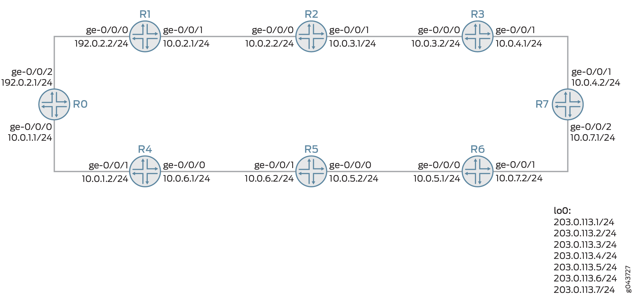
Figure 1 shows SRGBs, prefix segments, and adjacency hold time configured in SPRING on routers R0 to R7.
Configuration
CLI Quick Configuration
To quickly configure this example, copy the
following commands, paste them into a text file, remove any line breaks,
change any details necessary to match your network configuration,
copy and paste the commands into the CLI at the [edit] hierarchy level, and then enter commit from configuration
mode.
This topology demonstrates IPv4 prefixes. The same is applicable for IPv6 prefixes.
R0
set chassis network-services enhanced-ip
set interfaces ge-0/0/0 vlan-tagging
set interfaces ge-0/0/0 unit 1 vlan-id 1
set interfaces ge-0/0/0 unit 1 family inet address 10.0.1.1/24
set interfaces ge-0/0/0 unit 1 family iso
set interfaces ge-0/0/2 vlan-tagging
set interfaces ge-0/0/2 unit 1 vlan-id 1
set interfaces ge-0/0/2 unit 1 family inet address 192.10.12.1/24
set interfaces ge-0/0/2 unit 1 family iso
set interfaces ge-0/0/2 unit 1 family mpls maximum-labels 5
set interfaces lo0 unit 0 family inet address 203.0.113.1/24
set interfaces lo0 unit 0 family iso address 49.0001.000a.0a0a.0a00
set routing-options autonomous-system 100
set routing-options router-id 203.0.113.1
set routing-options forwarding-table export pplb
set routing-options forwarding-table chained-composite-next-hop ingress l3vpn
set protocols rsvp interface all link-protection
set protocols mpls traffic-engineering
set protocols mpls interface all
set protocols isis export prefix-sid
set protocols isis backup-spf-options remote-backup-calculation
set protocols isis backup-spf-options use-source-packet-routing
set protocols isis graceful-restart restart-duration 30
set protocols isis source-packet-routing adjacency-segment hold-time 240000
set protocols isis source-packet-routing srgb start-label 800000
set protocols isis source-packet-routing srgb index-range 40000
set protocols isis source-packet-routing explicit-null
set protocols isis interface ge-0/0/0.1 node-link-protection
set protocols isis interface ge-0/0/2.1 node-link-protection
set protocols isis interface all node-link-protection
set protocols isis interface fxp0.0 disable
set protocols isis interface lo0.0 passive
set policy-options policy-statement pplb then load-balance per-packet
set policy-options policy-statement prefix-sid term 1 from route-filter 203.0.113.1/24 exact
set policy-options policy-statement prefix-sid term 1 then prefix-segment index 1000
set policy-options policy-statement prefix-sid term 1 then prefix-segment node-segment
set policy-options policy-statement prefix-sid term 1 then accept
R1
set chassis network-services enhanced-ip
set interfaces ge-0/0/0 vlan-tagging
set interfaces ge-0/0/0 unit 1 vlan-id 1
set interfaces ge-0/0/0 unit 1 family inet address 192.0.2.2/24
set interfaces ge-0/0/0 unit 1 family iso
set interfaces ge-0/0/0 unit 1 family mpls
set interfaces ge-0/0/1 vlan-tagging
set interfaces ge-0/0/1 unit 1 vlan-id 1
set interfaces ge-0/0/1 unit 1 family inet address 10.0.2.1/24
set interfaces ge-0/0/1 unit 1 family iso
set interfaces ge-0/0/1 unit 1 family mpls
set interfaces lo0 unit 0 family inet address 203.0.113.2/24
set interfaces lo0 unit 0 family iso address 49.0001.0001.0101.0100
set routing-options router-id 203.0.113.2
set routing-options forwarding-table export pplb
set protocols rsvp interface all link-protection
set protocols mpls traffic-engineering
set protocols mpls interface all
set protocols isis export prefix-sid
set protocols isis backup-spf-options per-prefix-calculation
set protocols isis backup-spf-options remote-backup-calculation
set protocols isis backup-spf-options use-source-packet-routing
set protocols isis traffic-engineering family inet shortcuts
set protocols isis graceful-restart restart-duration 30
set protocols isis source-packet-routing adjacency-segment hold-time 240000
set protocols isis source-packet-routing srgb start-label 800000
set protocols isis source-packet-routing srgb index-range 40000
set protocols isis source-packet-routing explicit-null
set protocols isis interface ge-0/0/0.1 node-link-protection
set protocols isis interface ge-0/0/1.1 node-link-protection
set protocols isis interface all node-link-protection
set protocols isis interface fxp0.0 disable
set protocols isis interface lo0.0 passive
set protocols isis label-switched-path to_r2
set policy-options policy-statement pplb then load-balance per-packet
set policy-options policy-statement prefix-sid term 1 from route-filter 203.0.113.2/24 exact
set policy-options policy-statement prefix-sid term 1 then prefix-segment index 1001
set policy-options policy-statement prefix-sid term 1 then prefix-segment node-segment
set policy-options policy-statement prefix-sid term 1 then accept
set policy-options policy-statement setpref from protocol isis
set policy-options policy-statement setpref from level 2
set policy-options policy-statement setpref then preference 11
set policy-options policy-statement setpref then local-preference 11
set policy-options policy-statement setpref then accept
R2
set chassis network-services enhanced-ip
set interfaces ge-0/0/0 vlan-tagging
set interfaces ge-0/0/0 encapsulation flexible-ethernet-services
set interfaces ge-0/0/0 unit 1 vlan-id 1
set interfaces ge-0/0/0 unit 1 family inet address 10.0.2.2/24
set interfaces ge-0/0/0 unit 1 family iso
set interfaces ge-0/0/0 unit 1 family mpls
set interfaces ge-0/0/1 vlan-tagging
set interfaces ge-0/0/1 encapsulation flexible-ethernet-services
set interfaces ge-0/0/1 unit 1 vlan-id 1
set interfaces ge-0/0/1 unit 1 family inet address 10.0.3.1/24
set interfaces ge-0/0/1 unit 1 family iso
set interfaces ge-0/0/1 unit 1 family mpls
set interfaces lo0 unit 0 family inet address 203.0.113.3/24
set interfaces lo0 unit 0 family iso address 49.0001.0002.0202.0200
set routing-options router-id 203.0.113.3
set routing-options forwarding-table export pplb
set protocols rsvp interface all link-protection
set protocols mpls label-switched-path to_r1 to 203.0.113.2
set protocols mpls label-switched-path to_r1 primary path1 deactivate protocols mpls label-switched-path to_r1
set protocols mpls path 10.0.2.1
set protocols mpls path path1 10.0.2.1 strict
set protocols mpls interface all
set protocols isis export leakl2tol1
set protocols isis export prefix-sid
set protocols isis backup-spf-options remote-backup-calculation
set protocols isis backup-spf-options use-source-packet-routing
set protocols isis source-packet-routing adjacency-segment hold-time 240000
set protocols isis source-packet-routing srgb start-label 800000
set protocols isis source-packet-routing srgb index-range 40000
set protocols isis source-packet-routing explicit-null
set protocols isis interface ge-0/0/0.1 node-link-protection
set protocols isis interface ge-0/0/1.1 node-link-protection
set protocols isis interface all node-link-protection
set protocols isis interface fxp0.0 disable
set protocols isis interface lo0.0 passive
set protocols isis label-switched-path to_r1
set policy-options policy-statement leakl2tol1 from protocol isis
set policy-options policy-statement leakl2tol1 from level 2
set policy-options policy-statement leakl2tol1 to protocol isis
set policy-options policy-statement leakl2tol1 to level 1
set policy-options policy-statement leakl2tol1 then accept
set policy-options policy-statement pplb then load-balance per-packet
set policy-options policy-statement prefix-sid term 1 from route-filter 203.0.113.3/24 exact
set policy-options policy-statement prefix-sid term 1 then prefix-segment index 1002
set policy-options policy-statement prefix-sid term 1 then prefix-segment node-segment
set policy-options policy-statement prefix-sid term 1 then accept
R3
set chassis network-services enhanced-ip
set interfaces ge-0/0/0 vlan-tagging
set interfaces ge-0/0/0 unit 1 vlan-id 1
set interfaces ge-0/0/0 unit 1 family inet address 10-.0.3.2/24
set interfaces ge-0/0/0 unit 1 family iso
set interfaces ge-0/0/0 unit 1 family mpls
set interfaces ge-0/0/1 vlan-tagging
set interfaces ge-0/0/1 unit 1 vlan-id 1
set interfaces ge-0/0/1 unit 1 family inet address 10.0.4.1/24
set interfaces ge-0/0/1 unit 1 family iso
set interfaces ge-0/0/1 unit 1 family mpls
set interfaces lo0 unit 0 family inet address 203.0.113.4/24
set interfaces lo0 unit 0 family iso address 49.0001.0003.0303.0300
set routing-options router-id 203.0.113.4
set routing-options forwarding-table export pplb
set protocols rsvp interface all link-protection
set protocols mpls interface all
set protocols isis export prefix-sid
set protocols isis backup-spf-options remote-backup-calculation
set protocols isis backup-spf-options use-source-packet-routing
set protocols isis source-packet-routing adjacency-segment hold-time 240000
set protocols isis source-packet-routing srgb start-label 800000
set protocols isis source-packet-routing srgb index-range 40000
set protocols isis source-packet-routing explicit-null
set protocols isis interface ge-0/0/0.1 node-link-protection
set protocols isis interface ge-0/0/1.1 node-link-protection
set protocols isis interface all node-link-protection
set protocols isis interface fxp0.0 disable
set protocols isis interface lo0.0 passive
set policy-options policy-statement pplb then load-balance per-packet
set policy-options policy-statement prefix-sid term 1 from route-filter 203.0.113.4/24 exact
set policy-options policy-statement prefix-sid term 1 then prefix-segment index 1003
set policy-options policy-statement prefix-sid term 1 then prefix-segment node-segment
set policy-options policy-statement prefix-sid term 1 then accept
R4
set chassis network-services enhanced-ip
set interfaces ge-0/0/0 vlan-tagging
set interfaces ge-0/0/0 unit 1 vlan-id 1
set interfaces ge-0/0/0 unit 1 family inet address 10.0.6.2/24
set interfaces ge-0/0/0 unit 1 family iso
set interfaces ge-0/0/0 unit 1 family mpls
set interfaces ge-0/0/1 vlan-tagging
set interfaces ge-0/0/1 unit 1 vlan-id 1
set interfaces ge-0/0/1 unit 1 family inet address 10.0.1.2/24
set interfaces ge-0/0/1 unit 1 family iso
set interfaces ge-0/0/1 unit 1 family mpls
set interfaces lo0 unit 0 family inet address 203.0.113.5/24
set interfaces lo0 unit 0 family iso address 49.0001.0004.0404.0400
set routing-options router-id 203.0.113.5
set routing-options forwarding-table export pplb
set protocols rsvp interface all link-protection
set protocols mpls interface all
set protocols isis export prefix-sid
set protocols isis backup-spf-options remote-backup-calculation
set protocols isis backup-spf-options use-source-packet-routing
set protocols isis source-packet-routing adjacency-segment hold-time 240000
set protocols isis source-packet-routing srgb start-label 800000
set protocols isis source-packet-routing srgb index-range 40000
set protocols isis source-packet-routing explicit-null
set protocols isis interface ge-0/0/0.1 node-link-protection
set protocols isis interface ge-0/0/1.1 node-link-protection
set protocols isis interface all node-link-protection
set protocols isis interface fxp0.0 disable
set protocols isis interface lo0.0 passive
set policy-options policy-statement pplb then load-balance per-packet
set policy-options policy-statement prefix-sid term 1 from route-filter 203.0.113.5/24 exact
set policy-options policy-statement prefix-sid term 1 then prefix-segment index 1004
set policy-options policy-statement prefix-sid term 1 then prefix-segment node-segment
set policy-options policy-statement prefix-sid term 1 then accept
R5
set chassis network-services enhanced-ip
set interfaces ge-0/0/0 vlan-tagging
set interfaces ge-0/0/0 unit 1 vlan-id 1
set interfaces ge-0/0/0 unit 1 family inet address 10.0.5.2/24
set interfaces ge-0/0/0 unit 1 family iso
set interfaces ge-0/0/0 unit 1 family mpls
set interfaces ge-0/0/1 vlan-tagging
set interfaces ge-0/0/1 unit 1 vlan-id 1
set interfaces ge-0/0/1 unit 1 family inet address 10.0.6.2/24
set interfaces ge-0/0/1 unit 1 family iso
set interfaces ge-0/0/1 unit 1 family mpls
set interfaces lo0 unit 0 family inet address 203.0.113.6/24
set interfaces lo0 unit 0 family iso address 49.0001.0005.0505.0500
set routing-options router-id 203.0.113.6
set routing-options forwarding-table export pplb
set protocols rsvp interface all link-protection
set protocols mpls interface all
set protocols isis export leakl2tol1
set protocols isis export prefix-sid
set protocols isis backup-spf-options remote-backup-calculation
set protocols isis backup-spf-options use-source-packet-routing
set protocols isis source-packet-routing adjacency-segment hold-time 240000
set protocols isis source-packet-routing srgb start-label 800000
set protocols isis source-packet-routing srgb index-range 40000
set protocols isis source-packet-routing explicit-null
set protocols isis interface ge-0/0/0.1 node-link-protection
set protocols isis interface ge-0/0/1.1 node-link-protection
set protocols isis interface all node-link-protection
set protocols isis interface fxp0.0 disable
set protocols isis interface lo0.0 passive
set policy-options policy-statement leakl2tol1 from protocol isis
set policy-options policy-statement leakl2tol1 from level 2
set policy-options policy-statement leakl2tol1 to protocol isis
set policy-options policy-statement leakl2tol1 to level 1
set policy-options policy-statement leakl2tol1 then accept
set policy-options policy-statement pplb then load-balance per-packet
set policy-options policy-statement prefix-sid term 1 from route-filter 203.0.113.6/24 exact
set policy-options policy-statement prefix-sid term 1 then prefix-segment index 1005
set policy-options policy-statement prefix-sid term 1 then prefix-segment node-segment
set policy-options policy-statement prefix-sid term 1 then accept
R6
set chassis network-services enhanced-ip
set interfaces ge-0/0/0 vlan-tagging
set interfaces ge-0/0/0 unit 1 vlan-id 1
set interfaces ge-0/0/0 unit 1 family inet address 10.0.5.1/24
set interfaces ge-0/0/0 unit 1 family iso
set interfaces ge-0/0/0 unit 1 family mpls
set interfaces ge-0/0/1 vlan-tagging
set interfaces ge-0/0/1 unit 1 vlan-id 1
set interfaces ge-0/0/1 unit 1 family inet address 10.0.6.2/24
set interfaces ge-0/0/1 unit 1 family iso
set interfaces ge-0/0/1 unit 1 family mpls
set interfaces lo0 unit 0 family inet address 203.0.113.7/24
set interfaces lo0 unit 0 family iso address 49.0001.0006.0606.0600
set routing-options router-id 203.0.113.7
set routing-options forwarding-table export pplb
set protocols rsvp interface all link-protection
set protocols mpls interface all
set protocols isis export prefix-sid
set protocols isis backup-spf-options remote-backup-calculation
set protocols isis backup-spf-options use-source-packet-routing
set protocols isis source-packet-routing adjacency-segment hold-time 240000
set protocols isis source-packet-routing srgb start-label 800000
set protocols isis source-packet-routing srgb index-range 40000
set protocols isis source-packet-routing explicit-null
set protocols isis interface ge-0/0/0.1 node-link-protection
set protocols isis interface ge-0/0/1.1 node-link-protection
set protocols isis interface all node-link-protection
set protocols isis interface fxp0.0 disable
set protocols isis interface lo0.0 passive
set policy-options policy-statement pplb then load-balance per-packet
set policy-options policy-statement prefix-sid term 1 from route-filter 203.0.113.7/24 exact
set policy-options policy-statement prefix-sid term 1 then prefix-segment index 1006
set policy-options policy-statement prefix-sid term 1 then prefix-segment node-segment
set policy-options policy-statement prefix-sid term 1 then accept
R7
set chassis network-services enhanced-ip
set interfaces ge-0/0/1 vlan-tagging
set interfaces ge-0/0/1 unit 1 vlan-id 1
set interfaces ge-0/0/1 unit 1 family inet address 10.0.4.2/24
set interfaces ge-0/0/1 unit 1 family iso
set interfaces ge-0/0/1 unit 1 family mpls
set interfaces ge-0/0/2 vlan-tagging
set interfaces ge-0/0/2 unit 1 vlan-id 1
set interfaces ge-0/0/2 unit 1 family inet address 10.0.7.1/24
set interfaces ge-0/0/2 unit 1 family iso
set interfaces ge-0/0/2 unit 1 family mpls
set interfaces lo0 unit 0 family inet address 203.0.113.8/24
set interfaces lo0 unit 0 family iso address 49.0001.0007.0707.0700
set routing-options router-id 203.0.113.8
set routing-options autonomous-system 100
set routing-options forwarding-table export pplb
set protocols rsvp interface all link-protection
set protocols mpls explicit-null
set protocols mpls interface all
set protocols isis export prefix-sid
set protocols isis backup-spf-options remote-backup-calculation
set protocols isis backup-spf-options use-source-packet-routing
set protocols isis source-packet-routing adjacency-segment hold-time 240000
set protocols isis source-packet-routing srgb start-label 800000
set protocols isis source-packet-routing srgb index-range 40000
set protocols isis source-packet-routing explicit-null
set protocols isis interface ge-0/0/1.1 node-link-protection
set protocols isis interface ge-0/0/2.1 node-link-protection
set protocols isis interface all node-link-protection
set protocols isis interface fxp0.0 disable
set protocols isis interface lo0.0 passive
set policy-options policy-statement pplb then load-balance per-packet
set policy-options policy-statement prefix-sid term 1 from route-filter 203.0.113.8/24 exact
set policy-options policy-statement prefix-sid term 1 then prefix-segment index 1007
set policy-options policy-statement prefix-sid term 1 then prefix-segment node-segment
set policy-options policy-statement prefix-sid term 1 then accept
set policy-options policy-statement setpref from protocol isis
set policy-options policy-statement setpref from level 2
set policy-options policy-statement setpref then preference 11
set policy-options policy-statement setpref then local-preference 11
set policy-options policy-statement setpref then accept
set policy-options policy-statement stat term 1 from protocol static
set policy-options policy-statement stat term 1 then accept
Configuring Router R4
Step-by-Step Procedure
The following example requires that you navigate various levels in the configuration hierarchy. For information about navigating the CLI, see Using the CLI Editor in Configuration Mode in the Junos OS CLI User Guide.
To configure Router R4:
Repeat this procedure for every router in the SPRING domain, after modifying the appropriate interface names, addresses, and any other parameters for each router.
Configure enhanced IP mode on the MX Series router because the SRGB functionality is supported on routers with MPCs and MIC interfaces only. A system reboot is required after you commit this configuration.
[edit chassis]
user@R4# set network-services enhanced-ip
Configure the interfaces.
[edit interfaces]
user@R4# set ge-0/0/0 vlan-tagging
user@R4# set ge-0/0/0 unit 1 vlan-id 1
user@R4# set ge-0/0/0 unit 1 family inet address 10.0.6.2/24
user@R4# set ge-0/0/0 unit 1 family iso
user@R4# set ge-0/0/0 unit 1 family mpls
user@R4# set ge-0/0/1 vlan-tagging
user@R4# set ge-0/0/1 unit 1 vlan-id 1
user@R4# set ge-0/0/1 unit 1 family inet address 10.0.1.2/24
user@R4# set ge-0/0/1 unit 1 family iso
user@R4# set ge-0/0/1 unit 1 family mpls
user@R4# set lo0 unit 0 family inet address 203.0.113.5/24
user@R4# set lo0 unit 0 family iso address 49.0001.0004.0404.0400
Configure the router ID for a routing option.
[edit routing-options]
user@R4# set router-id 203.0.113.5
Configure the export policy for the forwarding table.
[edit routing-options]
user@R4# set forwarding-table export pplb
Enable RSVP link protection on the all interfaces.
[edit protocols rsvp]
user@R4# set interface all link-protection
Configure the MPLS interface.
[edit protocols mpls]
user@R4# set interface all
Configure the export policy for the IS-IS protocol.
[edit protocols isis]
user@R4# set export prefix-sid
Configure backup shortest-path-first options to calculate remote loop-free alternate (LFA) backup next hops and to use SPRING routed paths for protection for the IS-IS protocol.
[edit protocols isis]
user@R4# set backup-spf-options remote-backup-calculation
user@R4# set backup-spf-options use-source-packet-routing
Configure adjacency segment hold time in SPRING for the IS-IS protocol.
[edit protocols isis]
user@R4# set source-packet-routing adjacency-segment hold-time 240000
Configure the start label and index range for segment routing global blocks (SRGBs) in SPRING for the IS-IS protocol.
[edit protocols isis]
user@R4# set source-packet-routing srgb start-label 800000
user@R4# set source-packet-routing srgb index-range 40000
Configure explicit null in SPRING for the IS-IS protocol.
[edit protocols isis]
user@R4# set source-packet-routing explicit-null
Configure the interfaces to protect from both link and node faults.
[edit protocols isis]
user@R4# set interface ge-0/0/0.1 node-link-protection
user@R4# set interface ge-0/0/1.1  node-link-protection
user@R4# set interface all node-link-protection
Disable the management interface and configure the loopback address as passive for the IS-IS protocol.
[edit protocols isis]
user@R4# set interface fxp0.0 disable
user@R4# set interface lo0.0 passive
Configure per packet load balancing for the routing policy.
[edit policy-options policy-statement pplb]
user@R4# set then load-balance per-packet
Configure the route filter for the routing policy term.
[edit policy-options policy-statement prefix-sid]
user@R4# set term 1 from route-filter 203.0.113.5/24  exact
Configure the index and node segment of the prefix segment for the routing policy term.
[edit policy-options policy-statement prefix-sid]
user@R4# set term 1 then prefix-segment index 1004
user@R4# set term 1 then prefix-segment node-segment
user@R4# set term 1 then accept
Results
From configuration mode, confirm your configuration by entering the show chassis, show interfaces, show protocols, show policy-options, and show routing-options commands. If the output does not display the intended configuration, repeat the instructions in this example to correct the configuration.
user@R4# show chassis
network-services enhanced-ip;
user@R4# show interfaces
ge-0/0/0 {
    vlan-tagging;
    unit 1 {
        vlan-id 1;
        family inet {
            address 10.0.6.2/24;
        }
        family iso;
    }
}
ge-0/0/1 {
    vlan-tagging;
    unit 1{
        vlan-id 1;
        family inet {
            address 10.0.1.2/24;
        }
        family iso;
        family mpls ;
    }
}
lo0 {
    unit 0 {
        family inet {
            address 203.0.113.5/24;
        }
        family iso {
            address 49.0001.0004.0404.0400;
        }
    }
}
user@R4# show protocols
rsvp {
    interface all {
        link-protection;
    }
}
mpls {
    interface all;
}
isis {
    export prefix-sid;
    backup-spf-options {
        remote-backup-calculation;
        use-source-packet-routing;
    }
    source-packet-routing {
        adjacency-segment hold-time 240000;
        srgb start-label 800000 index-range 40000;
        explicit-null;
    }
    interface ge-0/0/0.1 {
        node-link-protection;
    }
    interface ge-0/0/1.1 {
        node-link-protection;
    }
    interface all {
        node-link-protection;
    }
    interface fxp0.0 {
        disable;
    }
    interface lo0.0 {
        passive;
    }
}
user@R4# show policy-options
policy-statement pplb {
    then {
        load-balance per-packet;
    }
}
policy-statement prefix-sid {
    term 1 {
        from {
            route-filter 203.0.113.5/24  exact;
        }
        then {
            prefix-segment index 1004 node-segment;
            accept;
        }
    }
}
user@R4# show routing-options
router-id 203.0.113.5;
forwarding-table {
    export pplb;
}
Verification
Confirm that the configuration is working properly.
- Verifying the IS-IS Adjacency Routes
- Verifying the IS-IS Overview Information
- Verifying the Segment Routing Route Entries for the IS-IS Protocol
- Verifying the MPLS Segment Routing Route Entries for the IS-IS Protocol
Verifying the IS-IS Adjacency Routes
Purpose
Verify the adjacency of Router R4.
Action
From operational mode, enter the show isis adjacency
detail command.
user@R4> show isis adjacency detail
R5
  Interface: ge-0/0/0.0, Level: 1, State: Up, Expires in 25 secs
  Priority: 64, Up/Down transitions: 1, Last transition: 1d 23:55:22 ago
  Circuit type: 3, Speaks: IP, IPv6, MAC address: 0:5:86:e:2b:0
  Topologies: Unicast
  Restart capable: Yes, Adjacency advertisement: Advertise
  LAN id: R5.02, IP addresses: 10.0.6.2
  Level 1 IPv4 Adj-SID: 16

R5
  Interface: ge-0/0/0.0, Level: 2, State: Up, Expires in 25 secs
  Priority: 64, Up/Down transitions: 1, Last transition: 1d 23:55:22 ago
  Circuit type: 3, Speaks: IP, IPv6, MAC address: 0:5:86:e:2b:0
  Topologies: Unicast
  Restart capable: Yes, Adjacency advertisement: Advertise
  LAN id: R5.02, IP addresses: 10.0.6.2
  Level 2 IPv4 Adj-SID: 17

R0
  Interface: ge-0/0/1.0, Level: 1, State: Up, Expires in 7 secs
  Priority: 64, Up/Down transitions: 1, Last transition: 1d 23:49:06 ago
  Circuit type: 3, Speaks: IP, IPv6, MAC address: 0:5:86:5e:8e:1
  Topologies: Unicast
  Restart capable: Yes, Adjacency advertisement: Advertise
  LAN id: R1.02, IP addresses: 10.0.1.1
  Level 1 IPv4 Adj-SID: 18

R0
  Interface: ge-0/0/1.0, Level: 2, State: Up, Expires in 8 secs
  Priority: 64, Up/Down transitions: 1, Last transition: 1d 23:49:06 ago
  Circuit type: 3, Speaks: IP, IPv6, MAC address: 0:5:86:5e:8e:1
  Topologies: Unicast
  Restart capable: Yes, Adjacency advertisement: Advertise
  LAN id: R1.02, IP addresses: 10.0.1.1
  Level 2 IPv4 Adj-SID: 19
Meaning
The output shows the IS-IS adjacency details of Router R4 with Router R0 and R5.
Verifying the IS-IS Overview Information
Purpose
Verify the IS-IS overview information of Router R4.
Action
From operational mode, enter the show isis overview command.
user@R4> show isis overview
Instance: master
  Router ID: 203.0.113.5
  Hostname: R4
  Sysid: 0100.0404.0404
  Areaid: 47.0005.80ff.f800.0000.0108.0001
  Adjacency holddown: enabled
  Maximum Areas: 3
  LSP life time: 1200
  Attached bit evaluation: enabled
  SPF delay: 200 msec, SPF holddown: 5000 msec, SPF rapid runs: 3
  IPv4 is enabled, IPv6 is enabled, SPRING based MPLS is enabled
  Traffic engineering: enabled
  Restart: Disabled
    Helper mode: Enabled
  Layer2-map: Disabled
  Source Packet Routing (SPRING): Enabled
    SRGB Config Range:
      SRGB Start-Label : 800000, SRGB Index-Range : 40000
    SRGB Block Allocation: Success
      SRGB Start Index : 800000, SRGB Size : 40000, Label-Range: [ 800000, 839999 ]
    Node Segments: Disabled
  Level 1
    Internal route preference: 15
    External route preference: 160
    Prefix export count: 0
    Wide metrics are enabled, Narrow metrics are enabled
    Source Packet Routing is enabled
  Level 2
    Internal route preference: 18
    External route preference: 165
    Prefix export count: 0
    Wide metrics are enabled, Narrow metrics are enabled
    Source Packet Routing is enabled
Meaning
The output displays the IS-IS overview information of the routing instance along with the SPRING details of Router R4.
Verifying the Segment Routing Route Entries for the IS-IS Protocol
Purpose
Verify the segment routing route entries of the routing table inet.3 for the IS-IS protocol.
Action
From operational mode, enter the show route table
inet.3 protocol isis command.
user@R4> show route table inet.3 protocol isis
inet.3: 2 destinations, 2 routes (2 active, 0 holddown, 0 hidden)
+ = Active Route, - = Last Active, * = Both

203.0.113.0/24     *[L-ISIS/14] 00:09:31, metric 10
                      to 10.0.6.2 via ge-0/0/0.0, Push 0
                    > to 10.0.1.1 via ge-0/0/1.0, Push 0
203.0.113.2/32     *[L-ISIS/14] 00:02:44, metric 20
                    > to 10.0.1.1 via ge-0/0/1.0, Push 801001
Meaning
The output shows the segment routing routes of routing table inet.3 for the IS-IS protocol.
Verifying the MPLS Segment Routing Route Entries for the IS-IS Protocol
Purpose
Verify the MPLS segment routing route entries for the IS-IS protocol.
Action
From operational mode, enter the show route table
mpls.0 protocol isis command.
user@R4> show route table mpls.0 protocol isis

 mpls.0: 23 destinations, 23 routes (23 active, 0 holddown, 0 hidden)
+ = Active Route, - = Last Active, * = Both

0                  *[MPLS/0] 2d 01:56:20, metric 1
                      to table inet.0
0(S=0)             *[MPLS/0] 2d 01:56:20, metric 1
                      to table mpls.0
1                  *[MPLS/0] 2d 01:56:20, metric 1
                      Receive
2                  *[MPLS/0] 2d 01:56:20, metric 1
                      to table inet6.0
2(S=0)             *[MPLS/0] 2d 01:56:20, metric 1
                      to table mpls.0
13                 *[MPLS/0] 2d 01:56:20, metric 1
                      Receive
16                 *[L-ISIS/14] 2d 01:52:56, metric 0
                    > to 10.0.6.2 via ge-0/0/0.0, Pop
16(S=0)            *[L-ISIS/14] 00:01:34, metric 0
                    > to 10.0.6.2 via ge-0/0/0.0, Pop
17                 *[L-ISIS/14] 2d 01:52:56, metric 0
                    > to 10.0.6.2 via ge-0/0/0.0, Pop
17(S=0)            *[L-ISIS/14] 00:10:49, metric 0
                    > to 10.0.6.2 via ge-0/0/0.0, Pop
18                 *[L-ISIS/14] 2d 01:46:40, metric 0
                    > to 10.0.1.1 via ge-0/0/1.0, Pop
18(S=0)            *[L-ISIS/14] 00:01:34, metric 0
                    > to 10.0.1.1 via ge-0/0/1.0, Pop
19                 *[L-ISIS/14] 2d 01:46:40, metric 0
                    > to 10.0.1.1 via ge-0/0/1.0, Pop
19(S=0)            *[L-ISIS/14] 00:10:49, metric 0
                    > to 10.0.1.1 via ge-0/0/1.0, Pop
801000             *[L-ISIS/14] 2d 01:46:40, metric 10
                      to 10.0.6.2 via ge-0/0/0.0, Swap 801000
                    > to 10.0.1.1 via ge-0/0/1.0, Swap 0
801000(S=0)        *[L-ISIS/14] 00:01:34, metric 10
                      to 10.0.6.2 via ge-0/0/0.0, Swap 801000
                    > to 10.0.1.1 via ge-0/0/1.0, Pop
801001             *[L-ISIS/14] 2d 01:46:14, metric 10
                      to 10.0.6.2 via ge-0/0/0.0, Swap 801001
                    > to 10.0.1.1 via ge-0/0/1.0, Swap 801001
801002             *[L-ISIS/14] 1d 21:57:31, metric 10
                      to 10.0.6.2 via ge-0/0/0.0, Swap 801002
                    > to 10.0.1.1 via ge-0/0/1.0, Swap 801002
801003             *[L-ISIS/14] 1d 21:56:57, metric 10
                      to 10.0.6.2 via ge-0/0/0.0, Swap 801003
                    > to 10.0.1.1 via ge-0/0/1.0, Swap 801003
801005             *[L-ISIS/14] 2d 01:46:40, metric 10
                      to 10.0.6.2 via ge-0/0/0.0, Swap 0
                    > to 10.0.1.1 via ge-0/0/1.0, Swap 801005
801005(S=0)        *[L-ISIS/14] 00:01:34, metric 10
                      to 10.0.6.2 via ge-0/0/0.0, Pop
                    > to 10.0.1.1 via ge-0/0/1.0, Swap 801005
801006             *[L-ISIS/14] 2d 01:46:40, metric 10
                      to 10.0.6.2 via ge-0/0/0.0, Swap 801006
                    > to 10.0.1.1 via ge-0/0/1.0, Swap 801006
801007             *[L-ISIS/14] 1d 21:56:24, metric 10
                      to 10.0.6.2 via ge-0/0/0.0, Swap 801007
                    > to 10.0.1.1 via ge-0/0/1.0, Swap 801007
Meaning
The output shows the MPLS segment routing route entries for protocol IS-IS.