ON THIS PAGE
Example: Configuring IS-IS Route Leaking from a Level 2 Area to a Level 1 Area
This example shows how to leak prefixes in an IS-IS network from a Level 2 area to a Level 1 area.
Requirements
No special configuration beyond device initialization is required before configuring this example.
Overview
Every routing protocol passes routing information up or down the routing hierarchy. This bidirectional flow of routing information is known as route leaking.
By default, IS-IS protocol leaks routing information from a Level 1 area to a Level 2 area. However, to leak routing information from a Level 2 area to a Level 1 area, an export policy must be explicitly configured.
Topology
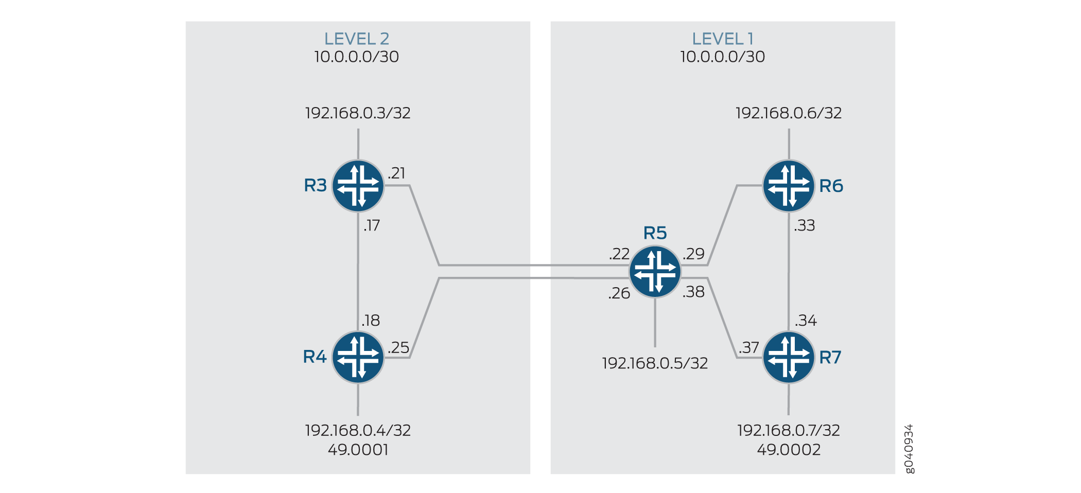
In this example, Devices R3 and R4 are configured in a Level 2 area. Devices R5, R6, and R7 are configured in a Level 1 area.
Figure 1 shows the topology used in this example.
Configuration
- Configuring Route Leaking from a Level 2 Area to a Level 1 Area
- Configuring Route Leaking from a Level 2 Area to a Level 1 Area
- Results
Configuring Route Leaking from a Level 2 Area to a Level 1 Area
CLI Quick Configuration
To quickly configure route leaking from a
Level 2 area to a Level 1 area, copy the following commands, paste
them into a text file, remove any line breaks, change any details
necessary to match your network configuration, and then copy and paste
the commands into the CLI at the [edit] hierarchy level.
Device R3
set interfaces fe-1/2/0 unit 0 description to-R4
set interfaces fe-1/2/0 unit 0 family inet address 10.0.0.17/30
set interfaces fe-1/2/0 unit 0 family iso
set interfaces fe-1/2/1 unit 0 description to-R5
set interfaces fe-1/2/1 unit 0 family inet address 10.0.0.21/30
set interfaces fe-1/2/1 unit 0 family iso
set interfaces lo0 unit 0 family inet address 192.168.0.3/32
set interfaces lo0 unit 0 family iso address 49.0001.0192.0168.0003.00
set policy-options policy-statement leak-L2-to-L1 from route-filter 192.168.0.0/24 orlonger
set policy-options policy-statement leak-L2-to-L1 from protocol isis
set policy-options policy-statement leak-L2-to-L1 from level 2
set policy-options policy-statement leak-L2-to-L1 to protocol isis
set policy-options policy-statement leak-L2-to-L1 to level 1
set policy-options policy-statement leak-L2-to-L1 then accept
set protocols isis interface fe-1/2/0.0 level 1 disable
set protocols isis interface fe-1/2/1.0 level 1 disable
set protocols isis interface lo0.0 level 1 disable
set protocols isis export leak-L2-to-L1
Device R4
set interfaces fe-1/2/0 unit 0 description to-R3
set interfaces fe-1/2/0 unit 0 family inet address 10.0.0.18/30
set interfaces fe-1/2/0 unit 0 family iso
set interfaces fe-1/2/1 unit 0 description to-R5
set interfaces fe-1/2/1 unit 0 family inet address 10.0.0.25/30
set interfaces fe-1/2/1 unit 0 family iso
set interfaces lo0 unit 0 family inet address 192.168.0.4/32
set interfaces lo0 unit 0 family iso address 49.0001.0192.0168.0004.00
set policy-options policy-statement leak-L2-to-L1 from route-filter 192.168.0.0/24 orlonger
set policy-options policy-statement leak-L2-to-L1 from protocol isis
set policy-options policy-statement leak-L2-to-L1 from level 2
set policy-options policy-statement leak-L2-to-L1 to protocol isis
set policy-options policy-statement leak-L2-to-L1 to level 1
set policy-options policy-statement leak-L2-to-L1 then accept
set protocols isis interface fe-1/2/0.0 level 1 disable
set protocols isis interface fe-1/2/1.0 level 1 disable
set protocols isis interface lo0.0 level 1 disable
set protocols isis export leak-L2-to-L1
Device R5
set interfaces fe-1/2/0 unit 0 description to-R3
set interfaces fe-1/2/0 unit 0 family inet address 10.0.0.22/30
set interfaces fe-1/2/0 unit 0 family iso
set interfaces fe-1/2/1 unit 0 description to-R4
set interfaces fe-1/2/1 unit 0 family inet address 10.0.0.26/30
set interfaces fe-1/2/1 unit 0 family iso
set interfaces fe-1/2/2 unit 0 description to-R6
set interfaces fe-1/2/2 unit 0 family inet address 10.0.0.29/30
set interfaces fe-1/2/2 unit 0 family iso
set interfaces fe-1/2/3 unit 0 description to-R7
set interfaces fe-1/2/3 unit 0 family inet address 10.0.0.38/30
set interfaces fe-1/2/3 unit 0 family iso
set interfaces lo0 unit 0 family inet address 192.168.0.5/32
set interfaces lo0 unit 0 family iso address 49.0002.0192.0168.0005.00
set protocols isis interface fe-1/2/0.0 level 1 disable
set protocols isis interface fe-1/2/1.0 level 1 disable
set protocols isis interface fe-1/2/2.0 level 2 disable
set protocols isis interface fe-1/2/3.0 level 2 disable
set protocols isis interface lo0.0 level 1 disable
Device R6
set interfaces fe-1/2/0 unit 0 description to-R5
set interfaces fe-1/2/0 unit 0 family inet address 10.0.0.30/30
set interfaces fe-1/2/0 unit 0 family iso
set interfaces fe-1/2/1 unit 0 description to-R7
set interfaces fe-1/2/1 unit 0 family inet address 10.0.0.33/30
set interfaces fe-1/2/1 unit 0 family iso
set interfaces lo0 unit 0 family inet address 192.168.0.6/32
set interfaces lo0 unit 0 family iso address 49.0002.0192.0168.0006.00
set protocols isis interface fe-1/2/0.0 level 2 disable
set protocols isis interface fe-1/2/1.0 level 2 disable
set protocols isis interface lo0.0 level 2 disable
Device R7
set interfaces fe-1/2/0 unit 0 description to-R6
set interfaces fe-1/2/0 unit 0 family inet address 10.0.0.34/30
set interfaces fe-1/2/0 unit 0 family iso
set interfaces fe-1/2/1 unit 0 description to-R5
set interfaces fe-1/2/1 unit 0 family inet address 10.0.0.37/30
set interfaces fe-1/2/1 unit 0 family iso
set interfaces lo0 unit 0 family inet address 192.168.0.7/32
set interfaces lo0 unit 0 family iso address 49.0002.0192.0168.0007.00
set protocols isis interface fe-1/2/0.0 level 2 disable
set protocols isis interface fe-1/2/1.0 level 2 disable
set protocols isis interface lo0.0 level 2 disable
Step-by-Step Procedure
Configuring Route Leaking from a Level 2 Area to a Level 1 Area
Step-by-Step Procedure
The following example requires that you navigate various levels in the configuration hierarchy. For information about navigating the CLI, see Using the CLI Editor in Configuration Mode in the Junos OS CLI User Guide.
To configure route leaking from a Level 2 area to a Level 1 area:
Configure the network interfaces.
Enable IS-IS on the interfaces by including the ISO address family on each interface.
[edit interfaces]
user@R3# set fe-1/2/0 unit 0 description to-R4
user@R3# set fe-1/2/0 unit 0 family inet address 10.0.0.17/30
user@R3# set fe-1/2/0 unit 0 family iso
user@R3# set fe-1/2/1 unit 0 description to-R5
user@R3# set fe-1/2/1 unit 0 family inet address 10.0.0.21/30
user@R3# set fe-1/2/1 unit 0 family iso
Similarly, configure other routers.
Configure two loopback interface addresses.
One address is for IPv4, and the other address is to enable the router to form adjacencies with other routers in the area.
[edit interfaces lo0 unit 0]
user@R3# set family inet address 192.168.0.3/32
user@R3# set family iso address 49.0001.0192.0168.0003.00
Specify the IS-IS level on a per-interface basis.
[edit protocols isis interface]
user@R3# set fe-1/2/0.0 level 1 disable
user@R3# set fe-1/2/1.0 level 1 disable
user@R3# set lo0.0 level 1 disable
Configure a route leaking policy on the routers configured in the Level 2 area to leak routes into the Level 1 area.
[edit policy-options policy-statement leak-L2-to-L1]
user@R3# set from route-filter 192.168.0.0/24 orlonger
user@R3# set from protocol isis
user@R3# set from level 2
user@R3# set to protocol isis
user@R3# set to level 1
user@R3# set then accept
[edit protocols isis]
user@R3# set export leak-L2-to-L1
Similarly, configure Device R4.
Results
From configuration mode, confirm your configuration by entering the show interfaces, show protocols isis, and show policy-options commands.
If the output does not display the intended configuration, repeat the instructions in this example to correct the configuration.
user@R3# show interfaces
fe-1/2/0 {
        unit 0 {
            description to-R4;
            family inet {
                address 10.0.0.17/30;
            }
            family iso;
        }
    }
fe-1/2/1 {
        unit 0 {
            description to-R5;
            family inet {
                address 10.0.0.21/30;
            }
            family iso;
        }
    }
lo0 {
        unit 0 {
            family inet {
                address 192.168.0.3/32;
            }
            family iso {
                address 49.0001.0192.0168.0003.00;
            }
        }
}user@R3# show protocols isis
export leak-L2-to-L1;
interface fe-1/2/0.0 {
level 1 disable;
}
interface fe-1/2/1.0 {
level 1 disable;
}
interface lo0.0 {
level 1 disable;
}
user@R3# show policy-options
policy-statement leak-L2-to-L1 {
        from {
            protocol isis;
            level 2;
            route-filter 192.168.0.0/24 orlonger;
        }
        to {
            protocol isis;
            level 1;
        }
        then accept;
    }
Similarly, confirm the configuration on all other routers. If
you are done configuring the routers, enter commit from
configuration mode.
Verification
Verifying Route Leaking from a Level 2 Area to a Level 1 Area
Purpose
Verify that IS-IS leaks routes from a Level 2 area to a Level 1 area.
Action
To verify that route leaking is taking place, use the following commands:
show isis adjacency (to verify that the IS-IS network is up and adjacencies have been established)
show isis database detail (to verify the presence of leaked routes)
From operational mode on Device R3, run the show isis adjacency command.
user@R3> show isis adjacency
Interface            System     L State        Hold (secs) SNPA
fe-1/2/0.0           R4         2  Up          7           0:5:85:8f:94:bd
fe-1/2/1.0           R5         2  Up          7           0:5:85:8f:94:bd
The output verifies that the interfaces on Device R3 are up and have established adjacencies with the connecting interfaces on Routers R4 and R5. If you don’t see the interfaces being functional, see the Results section for troubleshooting your configuration.
From operational mode on Device R3, run the show isis database detail command.
user@R3> show isis database detail
IS-IS level 1 link-state database:

R3.00-00 Sequence: 0x19, Checksum: 0x3453, Lifetime: 1078 secs
   IP prefix: 192.168.0.4/32                  Metric:       10 Internal Down
   IP prefix: 192.168.0.5/32                  Metric:       10 Internal Down
   IP prefix: 192.168.0.6/32                  Metric:       20 Internal Down
   IP prefix: 192.168.0.7/32                  Metric:       20 Internal Down

IS-IS level 2 link-state database:

R3.00-00 Sequence: 0x1c, Checksum: 0xc657, Lifetime: 1078 secs
   IS neighbor: R4.02                     Metric:       10
   IS neighbor: R5.02                     Metric:       10
   IP prefix: 10.0.0.16/30                    Metric:       10 Internal Up
   IP prefix: 10.0.0.20/30                    Metric:       10 Internal Up
   IP prefix: 192.168.0.3/32                  Metric:        0 Internal Up

R4.00-00 Sequence: 0x19, Checksum: 0xea13, Lifetime: 1076 secs
   IS neighbor: R4.02                     Metric:       10
   IS neighbor: R5.03                     Metric:       10
   IP prefix: 10.0.0.16/30                    Metric:       10 Internal Up
   IP prefix: 10.0.0.24/30                    Metric:       10 Internal Up
   IP prefix: 192.168.0.4/32                  Metric:        0 Internal Up

R4.02-00 Sequence: 0x17, Checksum: 0xecab, Lifetime: 1076 secs
   IS neighbor: R3.00                     Metric:        0
   IS neighbor: R4.00                     Metric:        0

R5.00-00 Sequence: 0x12, Checksum: 0xf4e5, Lifetime: 1076 secs
   IS neighbor: R5.02                     Metric:       10
   IS neighbor: R5.03                     Metric:       10
   IP prefix: 10.0.0.20/30                    Metric:       10 Internal Up
   IP prefix: 10.0.0.24/30                    Metric:       10 Internal Up
   IP prefix: 10.0.0.28/30                    Metric:       10 Internal Up
   IP prefix: 10.0.0.32/30                    Metric:       20 Internal Up
   IP prefix: 10.0.0.36/30                    Metric:       10 Internal Up
   IP prefix: 192.168.0.5/32                  Metric:        0 Internal Up
   IP prefix: 192.168.0.6/32                  Metric:       10 Internal Up
   IP prefix: 192.168.0.7/32                  Metric:       10 Internal Up

R5.02-00 Sequence: 0xb, Checksum: 0x2d74, Lifetime: 1076 secs
   IS neighbor: R3.00                     Metric:        0
   IS neighbor: R5.00                     Metric:        0

R5.03-00 Sequence: 0xb, Checksum: 0x6c32, Lifetime: 1076 secs
   IS neighbor: R4.00                     Metric:        0
   IS neighbor: R5.00                     Metric:        0
The
Downkeyword identifies the routes that have successfully leaked from the Level 2 area to the Level 1 area.
Meaning
Route leaking from a Level 2 to a Level 1 area is functioning as expected.