Configuring VLAN Tagging
Virtual LANs (VLANs) allow network architects to segment LANs into different broadcast domains based on logical groupings. The topic below describes the configuration of these tagged VLANs, VLAN IDs, and supported Ethernet interface types.
Understanding Virtual LANs
A LAN is a single broadcast domain. When traffic is broadcast, all hosts within the LAN receive the broadcast traffic. A LAN is determined by the physical connectivity of devices within the domain.
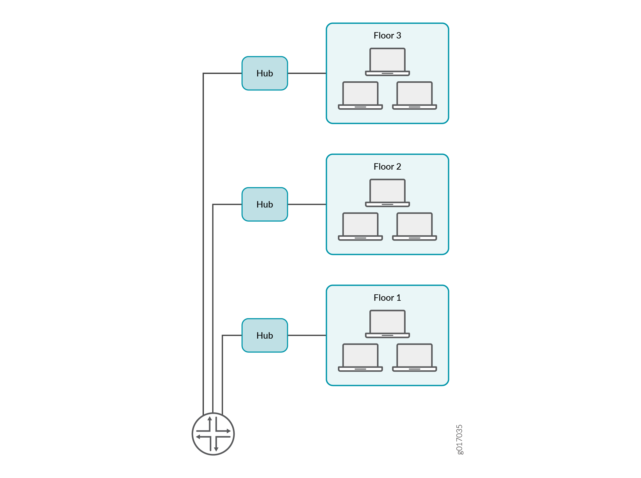
Within a traditional LAN, hosts are connected by a hub or repeater that propagates any incoming traffic throughout the network. Each host and its connecting hubs or repeaters make up a LAN segment. LAN segments are connected through switches and bridges to form the broadcast domain of the LAN. Figure 1 shows a typical LAN topology.
Virtual LANs (VLANs) allow network architects to segment LANs into different broadcast domains based on logical groupings. Because the groupings are logical, the broadcast domains are not determined by the physical connectivity of the devices in the network. Hosts can be grouped according to a logical function, to limit the traffic broadcast within the VLAN to only the devices for which the traffic is intended.
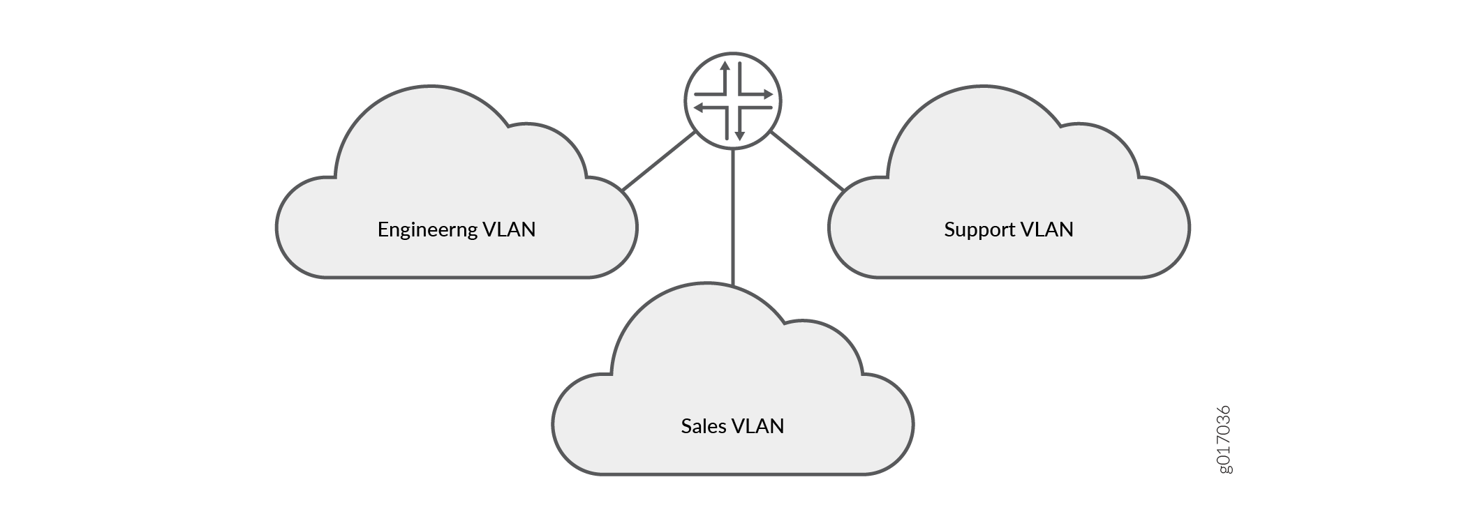
Suppose a corporate network has three major organizations: engineering, sales, and support. Using VLAN tagging, hosts within each organization can be tagged with a different VLAN identifier. Traffic sent to the broadcast domain is then checked against the VLAN identifier and broadcast to only the devices in the appropriate VLAN. Figure 2 shows a typical VLAN topology.
See Also
VLAN IDs and Ethernet Interface Types Supported
The below table lists VLAN ID range by interface type supported:
Interface Type |
Interface Type VLAN ID Range |
|---|---|
2-Port 10-Gigabit Ethernet |
1 through 4094 |
10-Gigabit Ethernet |
1 through 4094 |
16-Port Gigabit Ethernet |
1 through 4094 |
24-Port Gigabit Ethernet |
1 through 4094 |
Aggregated Ethernet for Fast Ethernet |
1 through 1023 |
Aggregate Ethernet for Gigabit Ethernet |
1 through 4094 |
Gigabit Ethernet |
1 through 4094 |
Management and internal Ethernet interfaces |
1 through 1023 |
See Also
Configuring VLAN Tagging
Use Feature Explorer to confirm platform and release support for specific features.
Review the Platform-Specific VLAN Behavior section for notes related to your platform.
See Table 2 for flexible VLANs.
| Number of Tags | VLAN ID |
|---|---|
0 (Untagged) |
Native |
1 (Tagged) |
Single |
2 (Dual tagged) |
Dual |
This topic includes the following sections:
- Configuring Single-Tag Framing
- Configuring Dual Tagging
- Configuring Mixed Tagging
- Configuring Mixed Tagging Support for Untagged Packets
Configuring Single-Tag Framing
To configure a device to receive and forward single-tag frames
with 802.1Q VLAN tags, include the vlan-tagging statement
at the [edit interfaces interface-name] hierarchy level:
[edit interfaces interface-name]
vlan-tagging;
Configuring Dual Tagging
To configure the device to receive and forward dual-tag frames
with 802.1Q VLAN tags, include the flexible-vlan-tagging statement at the [edit interfaces interface-name] hierarchy level:
[edit interfaces interface-name]
flexible-vlan-tagging;
Configuring Mixed Tagging
To configure mixed tagging, include the flexible-vlan-tagging statement at the [edit interfaces ge-fpc/pic/port ] hierarchy
level. You must also include the vlan-tags statement with inner and outer options or the vlan-id statement at the [edit interfaces ge-fpc/pic/port unit logical-unit-number] hierarchy level:
[edit interfaces ge-fpc/pic/port]
flexible-vlan-tagging;
unit logical-unit-number {
    vlan-id number;
    family family {
        address address;
    }
}
unit logical-unit-number {
    vlan-tags inner tpid.vlan-id outer tpid.vlan-id;
    family family {
        address address;
    }
}
When you configure the physical interface MTU for mixed tagging, you must increase the MTU to 4 bytes more than the MTU value you would configure for a standard VLAN-tagged interface.
For example, if the MTU value is configured to be 1018 on a VLAN-tagged interface, then the MTU value on a flexible VLAN tagged interface must be 1022—4 bytes more. The additional 4 bytes accommodates the future addition of a stacked VLAN tag configuration on the same physical interface.
The following example configures mixed tagging. Dual-tag and single-tag logical interfaces are under the same physical interface:
[edit interfaces ge-0/2/0]
flexible-vlan-tagging;
unit 0 {
    vlan-id 232;
    family inet {
        address 10.66.1.2/30;
    }
}
unit 1 {
    vlan-tags outer 0x8100.222 inner 0x8100.221;
    family inet {
        address 10.66.1.2/30;
    }
}
Configuring Mixed Tagging Support for Untagged Packets
You can configure mixed tagging support for untagged packets
on a port. Untagged packets are accepted on the same mixed VLAN-tagged
port. To accept untagged packets, include the native-vlan-id statement and the flexible-vlan-tagging statement at
the [edit interfaces interface-name] hierarchy level:
[edit interfaces ge-fpc/pic/port]
flexible-vlan-tagging;
native-vlan-id number;
The flexible-vlan-tagging is supported only with
either no encapsulation or VPLS VLAN encapsulation.
The logical interface on which
untagged packets are to be received must be configured with the same
native VLAN ID as that configured on the physical interface. To configure
the logical interface, include the vlan-id statement (matching
the native-vlan-id statement on the physical interface)
at the [edit interfaces interface-name unit logical-unit-number] hierarchy level.
The following example configures untagged packets to be mapped to logical unit number 0:
[edit interfaces ge-0/2/0]
flexible-vlan-tagging;
native-vlan-id 232;
unit 0 {
    vlan-id 232;
    family inet {
        address 10.66.1.2/30;
    }
}
unit 1 {
    vlan-tags outer 0x8100.222 inner 0x8100.221;
    family inet {
        address 10.66.1.2/30;
    }
}
Platform-Specific VLAN Behavior
Use Feature Explorer to confirm platform and release support for specific features.
Use the following table to review platform-specific VLAN configuration behavior for your platform:
|
Platform |
Difference |
|---|---|
|
SRX Series |
|