Configure GRE Keepalive Time
Learn about GRE tunnel interfaces and how to configure GRE keepalive time.
GRE Keepalive Time Overview
GRE tunnel interfaces do not have a built-in mechanism for detecting when a tunnel is down. You can enable keepalive messages to serve as the detection mechanism.
Use Keepalive support for GRE interfaces to confirm platform and release support.
Keepalives can be configured on the physical or on the logical interface. If configured on the physical interface, keepalives are sent on all logical interfaces that are part of the physical interface. If configured on an individual logical interface, keepalives are only sent to that logical interface. In addition to configuring a keepalive, you must configure the hold time.
Configure the keepalives on a GRE tunnel interface by including both the
keepalive-time statement and the hold-time
statement at the [edit protocols oam gre-tunnel interface
interface-name] hierarchy level.
For proper operation of keepalives on a GRE interface, you must also include the
family inet statement at the [edit interfaces
interface-name unit unit]
hierarchy level. If you do not include this statement, the interface is marked as
down.
Configure GRE Keepalive Time
Use Keepalive support for GRE interfaces to confirm platform and release support.
- Configure Keepalive Time and Hold Time for a GRE Tunnel Interface
- Display GRE Keepalive Time Configuration
- Display Keepalive Time Information on a GRE Tunnel Interface
Configure Keepalive Time and Hold Time for a GRE Tunnel Interface
Configure the keepalives on a GRE tunnel interface by including both the
keepalive-time statement and the hold-time
statement at the [edit protocols oam gre-tunnel interface
interface-name] hierarchy level.
For proper operation of keepalives on a GRE interface, also include the
family inet statement at the [edit interfaces
interface-name unit unit]
hierarchy level. If you do not include this statement, the interface is marked as
down.
To configure a GRE tunnel interface:
To configure keepalive time for a GRE tunnel interface:
Configure the Operation, Administration, and Maintenance (OAM) protocol at the
[edit protocols]hierarchy level for the GRE tunnel interface.[edit] user@host# edit protocols oam
Configure the GRE tunnel interface option for OAM protocol.
[edit protocols oam] user@host# edit gre-tunnel interface interface-name
Configure the keepalive time from 1 through 50 seconds for the GRE tunnel interface.
[edit protocols oam gre-tunnel interface interface-name] user@host# set keepalive-time seconds
Configure the hold time from 5 through 250 seconds. Note that the hold time must be at least twice the keepalive time.
[edit protocols oam gre-tunnel interface interface-name] user@host# set hold-time seconds
Display GRE Keepalive Time Configuration
Purpose
Display the configured keepalive time value as 10 and hold time value as 30 on a GRE tunnel interface (for example, gr-1/1/10.1):
Action
To display the configured values on the GRE tunnel interface,
run the show oam gre-tunnel command
at the [edit protocols] hierarchy level:
[edit protocols]
user@host# show oam gre-tunnel
    interface gr-1/1/10.1 {
        keepalive-time 10;
        hold-time 30;
    }
Display Keepalive Time Information on a GRE Tunnel Interface
Purpose
Display the current status information of a GRE tunnel interface when keepalive time and hold time parameters are configured on it and when the hold time expires.
Action
To verify the current status information on a GRE tunnel
interface (for example,
gr-3/3/0.3), run the show interfaces
gr-3/3/0.3 terse and show interfaces
gr-3/3/0.3 extensive operational commands.
show interfaces

                    gr-3/3/0.3 terse
user@host> show interfaces gr-3/3/0.3 terse

                                                                                                                      Interface               Admin Link Proto    Local                 Remote
                                                                                                                      gr-3/3/0.3              up    up   inet     200.1.3.1/24
                                                                                                                      mpls
show interfaces gr-3/3/0.3 extensive
user@host> show interfaces gr-3/3/0.3 extensive
Logical interface gr-3/3/0.3 (Index 73) (SNMP ifIndex 594) (Generation 900)
                                                                                                                            Flags: Point-To-Point SNMP-Traps 0x4000 IP-Header 10.1.19.11:10.1.19.12:47:df:64:0000000000000000 Encapsulation: GRE-NULL
                                                                                                                            Gre keepalives configured: On, Gre keepalives adjacency state: down
                                                                                                                              ^^^^^^^^^^^^^^^^^^^^^^^^^^^^^^^^^^^^^^^^^^^^^^^^^^^^^^^^^^^^^^^^^^^^^^^^
                                                                                                                              Traffic statistics:
                                                                                                      Input  bytes  :             15629992
                                                                                                      Output bytes  :             15912273
                                                                                                      Input  packets:               243813
                                                                                                      Output packets:               179476
                                                                                                      Local statistics:
                                                                                                      Input  bytes  :             15322586
                                                                                                      Output bytes  :             15621359
                                                                                                      Input  packets:               238890
                                                                                                      Output packets:               174767
                                                                                                      Transit statistics:
                                                                                                      Input  bytes  :               307406                    0 bps
                                                                                                      Output bytes  :               290914                    0 bps
                                                                                                      Input  packets:                 4923                    0 pps
                                                                                                      Output packets:                 4709                    0 pps
                                                                                                      Protocol inet, MTU: 1476, Generation: 1564, Route table: 0
                                                                                                      Flags: Sendbcast-pkt-to-re
                                                                                                      Addresses, Flags: Dest-route-down Is-Preferred Is-Primary
                                                                                                        ^^^^^^^^^^^^^^^^^^^^^^^^^^^^^^^^^^^^^^^^
                                                                                                        Destination: 200.1.3/24, Local: 200.1.3.1, Broadcast: 200.1.3.255, Generation: 1366
                                                                                                        Protocol mpls, MTU: 1464, Maximum labels: 3, Generation: 1565, Route table: 0
When the hold time expires:
-
The GRE tunnel will stay up even though the interface cannot send or receive traffic.
-
The
Linkstatus will beUpand theGre keepalives adjacency statewill beDown.
Meaning
The current status information of a GRE tunnel interface with keepalive time and hold time parameters is displayed as expected when the hold time expires.
Example: GRE Configuration
GRE is an IP encapsulation protocol that is used to transport packets over a network. Information is sent from one network to the other through a GRE tunnel. GRE encapsulates a payload as a GRE packet. This GRE packet is encapsulated in an outer protocol (delivery protocol). GRE tunnel endpoints forward payloads into GRE tunnels for routing packets to the destination. GRE is removed after reaching the endpoint. The payload is then transmitted to its final destination. The primary use of GRE is to carry non-IP packets through an IP network; however, GRE is also used to carry IP packets through an IP cloud.
Requirements
-
Configure a GRE (gr-) interface. The gr- interface contains a local address and destination address. It comes up as soon as it is configured. You can even configure an IP address on the gr- interface.
-
Configure a route to reach the destination subnet (end-to-end connectivity). You can configure either a static route through the gr- interface or use an IGP such as OSPF.
Overview
GRE tunnels are designed to be completely stateless, which means that each tunnel endpoint does not keep any information about the state or availability of the remote tunnel endpoint. A GRE tunnel interface becomes active once configured. It stays active with a valid tunnel source address or interface.
Configuration
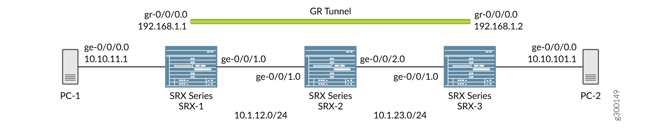
By default, the local subnet interface is ge-0/0/0 with IPv4 address as 10.10.11.1/24. The destination subnet is 10.10.10.0/24 with the tunnel endpoint IPv4 interface as 10.10.10.1/24.
GRE configuration shows the default configuration between the tunnel interfaces on SRX Series Firewalls.
Configuring a Route to Reach the Destination Subset
Step-by-Step Procedure
You can either configure a static route through the gr- interface or by using IGP.
-
Configure the local subnet interface ge-0/0/0 interface.
[edit interfaces]
user@host# set interfaces ge-0/0/0 unit 0 family inet address 10.10.11.1/24
-
Configure the interface ge-0/0/1.
[edit interfaces]
user@host# set interfaces ge-0/0/1 unit 0 family inet address 10.1.12.1/24
-
Configure the gr- tunnel endpoints and specify the source address, destination address, and family as inet for the tunnel endpoints.
[edit interfaces]
user@host# set interfaces gr-0/0/0  unit 0 tunnel source 10.1.12.1 destination 10.1.23.1
user@host# set interfaces gr-0/0/0 unit 0 family inet address 192.168.1.1/24
-
The configured interfaces are bound to a security zone at the
[edit security]hierarchy level. Use theshow zonescommand to view the zones. Configure the zones as follows:[edit security zones security-zones trust]] user@host# set host-inbound-traffic system-services all user@host# set host-inbound-traffic protocols all user@host# set interfaces gr-0/0/0.0 user@host# set zones zone names protocols all
[edit security zones security-zones untrust]]
user@host# set host-inbound-traffic system-services all
user@host# set host-inbound-traffic protocols all
-
View the configured interfaces at the
[edit
                                    interfaces]
hierarchy level using theshowcommand.[edit interfaces] user@host# set routing options static route 10.10.10.0/24 next hop gr-0/0/0.0
-
Avoid defining a static route by configuring OSPF between gr-0/0/0 interfaces on both sides. Mark the internal subnet as a passive neighbor to receive internal routes. Configure OSPF at the
[edit protocols]hierarchy level and view it using theshowcommand.[edit protocols] user@host# set protocols ospf area 0.0.0.0 interface gr-0/0/0.0
Results
In configuration mode, confirm your configuration on the devices by entering
the show command. If the output does not display the
intended configuration, repeat the configuration instructions in this
example to correct it.
GRE configuration using the static route:
[edit interfaces]
root@SRX-1# show
ge-0/0/0 {
    unit 0 {
        family inet {
            address 10.10.11.1/24;
        }
    }
}

gr-0/0/0 {
    unit 0 {
        tunnel {
            source 10.1.12.1;
            destination 10.1.23.1;
        }
        family inet {
            address 192.168.1.1/24;
        }
    }
}

ge-0/0/1 {
    unit 0 {
        family inet {
            address 10.1.12.1/24;
        }
    }
}

[edit security]
root@SRX-1# show
zones {
    security-zone trust {
        host-inbound-traffic {
            system-services {
                all;
            }
            protocols {
                all;
            }
        }
        interfaces {
            gr-0/0/0.0;
        }
    }
}

root@SRX-1# show routing-options
static {
    route 10.10.10.0/24 next-hop gr-0/0/0.0;
}
GRE configuration using OSPF configured between interfaces gr-0/0/0 on both sides and internal subnet as passive neighbor:
[edit protocols]
root@SRX-1# show
ospf {
    area 0.0.0.0 {
        interface gr-0/0/0.0;
        interface ge-0/0/0.0 {
            passive;
        }
    }
}
Verification
To verify that the configuration of GRE on the SRX Series Firewall is successful, perform the following tasks:
- Verification of the GRE Interfaces
- Verification of the Route
- Verification of Traffic Through GRE Tunnel
Verification of the GRE Interfaces
Purpose
Verify that the GRE interfaces are up.
Action
Run the show interfaces command at the [edit
interfaces] hierarchy level:
show interfaces gr-0/0/0 terse [edit interfaces] Interface Admin Link Proto Local Remote gr-0/0/0 up up gr-0/0/0.0 up up inet 192.168.1.1/24
Verification of the Route
Purpose
Verify that the route for the destination network is reachable through the GRE tunnel interface.
Action
Run the show route forwarding-table matching
10.10.10.0/24
command at the [edit interfaces] hierarchy
level:
[edit interfaces] user@router# run show route forwarding-table matching 10.10.10.0/24 Routing table: default.inet Internet: .... Destination Type RtRef Next hop Type Index NhRef Netif 10.10.10.0/24 user 0 ucst 595 2 gr-0/0/0.0
Verification of Traffic Through GRE Tunnel
Purpose
Send the traffic to the destination subnet and verify when the GRE interface is up.
Action
Run the show interfaces gr-0/0/0 extensive operational
command. Also verify that the packets are leaving through the gr-
interface.
user@host> show interfaces gr-0/0/0 extensive
Physical interface: gr-0/0/0, Enabled, Physical link is Up
Interface index: 134, SNMP ifIndex: 40, Generation: 17
Type: GRE, Link-level type: GRE, MTU: Unlimited, Speed: 800mbps
Hold-times : Up 0 ms, Down 0 ms
Device flags : Present Running
Interface flags: Point-To-Point SNMP-Traps
Statistics last cleared: 2005-08-05 21:39:41 UTC (00:00:47 ago)
Traffic statistics:
Input bytes : 8400 0 bps
Output bytes : 8400 0 bps
Input packets: 100 0 pps
Output packets: 100 0 pps

Logical interface gr-0/0/0.0 (Index 72) (SNMP ifIndex 28) (Generation 17)
Flags: Point-To-Point SNMP-Traps 16384
IP-Header 10.1.12.1:10.1.23.1:47:df:64:0000000000000000
Encapsulation: GRE-NULL
Traffic statistics:
Input bytes : 8400
Output bytes : 8400
Input packets: 100
Output packets: 100
Local statistics:
Input bytes : 0
Output bytes : 0
Input packets: 0
Output packets: 0
Transit statistics:
Input bytes : 8400 0 bps
Output bytes : 8400 0 bps
Input packets: 100 0 pps
Output packets: 100 0 pps
Protocol inet, MTU: 1476, Generation: 25, Route table: 0
Flags: None
Addresses, Flags: Is-Primary
Destination: Unspecified, Local: 192.168.0.1, Broadcast: Unspecified,
Generation: 30
Example: Configure GRE over IPsec Tunnels
Requirements
Overview
GRE tunnels offer minimal security, whereas an IPsec tunnel offers enhanced security in terms of confidentiality, data authentication, and integrity assurance. Also, IPsec cannot directly support multicast packets. However, if an encapsulated GRE tunnel is used first, an IPsec tunnel can then be used to provide security to the multicast packet. In a GRE over IPsec tunnel, all of the routing traffic (IP and non-IP) can be routed through. When the original packet (IP/non-IP) is GRE encapsulated, it has an IP header as defined by the GRE tunnel, normally the tunnel interface IP addresses. The IPsec protocol can understand the IP packet; so it encapsulates the GRE packet to make it GRE over IPsec.
The basic steps involved in configuring GRE over IPsec are as follows:
Configure the route-based IPsec tunnel.
Configure the GRE tunnel.
Configure a static route with the destination as the remote subnet through the gr- interface.
Configure the static route for the GRE endpoint with the st0 interface as next hop.
Configuration
In this example, the default configuration has the local subnet interface as ge-0/0/0 with the IPv4 address as 10.10.11.1/24. The destination subnet is 10.10.10.0/24. The gr-0/0/0 interface tunnel endpoints are loopback addresses on both the sides, with the local loopback IPv4 address as 172.20.1.1 and the remote loopback IPv4 address as 172.20.1.2. The gr-0/0/0, st0 and lo0 interfaces are bound to a security zone and policies are created accordingly.
Configuring a GRE Interface over an IPsec Tunnel
Step-by-Step Procedure
Configure the GRE at the
[set interfaces interface-name unit
                                        unit-number]
hierarchy level.[edit interfaces] user@host# set interfaces ge-0/0/0 unit 0 family inet address 10.10.11.1/24
Configure the gr- tunnel endpoints and specify the source address, destination address, and family as inet for the tunnel endpoints.
[edit interfaces]
user@host# set interfaces gr-0/0/0  unit 0 tunnel source 172.20.1.1 destination 172.20.1.2
user@host# set interfaces gr-0/0/0  unit 0 family inet 192.168.1.1/24
Similarly configure the lo0 and st0 interface with the family set as inet.
[edit interfaces]
user@host# set interfaces lo0 unit 0 family inet address 172.20.1.1/32
[edit interfaces]
user@host# set interfaces st0 unit 0 family inet
Configure the GRE interfaces with security zones. Use the
show zonescommand to view the zones, where the configured tunnel interfaces, lo0 and st0 are displayed.[edit security zones security-zones trust]] user@host# set host-inbound-traffic system-services all user@host# set host-inbound-traffic protocols all user@host# set interfaces gr-0/0/0.0 user@host# set zones zone names protocols all user@host# set interfaces lo0.0 user@host# set interfaces st0.0
[edit security zones security-zones untrust]]
user@host# set host-inbound-traffic system-services all
user@host# set host-inbound-traffic protocols all
user@host# set interfaces gr-0/0/0.0.1
user@host# set interfaces lo0.0
user@host# set interfaces st0.0
Results
In configuration mode, confirm your interface configuration
by entering the show command. The configured interfaces
are bound to a security zone at the [edit security] hierarchy
level. Use the show zones command to view the zones, where
the configured interfaces (gr-, st0.0, and lo0) are displayed. If
the output does not display the intended configuration, repeat the
configuration instructions in this example to correct it.
Parameters for configuring the GRE interfaces:
user@host> show interfaces
ge-0/0/0 {
    unit 0 {
        family inet {
            address 10.10.11.1/24;
        }
    }
}

gr-0/0/0 {
    unit 0 {
        tunnel {
            source 172.20.1.1;
            destination 172.20.1.2;
        }
        family inet {
            address 192.168.1.1/24;
        }
    }
}

lo0 {
    unit 0 {
        family inet {
            address 172.20.1.1/32;
        }
    }
}

st0 {
    unit 0 {
        family inet;
    }
}

[edit]
root@Juniper# show
routing-options {
    static {
        route 10.10.10.0/24 next-hop gr-0/0/0.0;
        route 172.20.1.2/32 next-hop st0.0;
    }
}
Parameters for configuring the GRE interfaces with security zones:
[edit security]
root@Juniper# show
zones {
    security-zone trust {
        host-inbound-traffic {
            system-services {
                all;
            }
            protocols {
                all;
            }
        }
        interfaces {
            gr-0/0/0.0;
            lo0.0;
            st0.0;
        }
    }
}
Example: Configure a GRE Tunnel When the Tunnel Destination Is in a Routing Instance
Overview
You can configure a GRE tunnel when the tunnel destination is in a default routing instance or non-default routing instance. Configuration of a GRE tunnel requires defining the tunnel source and the tunnel destination addresses. If the tunnel destination is in a routing instance and multiple routing instances exist, specify the correct routing instance. Also, define the routing table to reach the tunnel destination address.
The tunnel destination address is by default considered to be reachable using the default routing table "inet.0".
Configuration
In this example, you can configure a GRE tunnel between the gr- interfaces on SRX Series Firewalls with two instances. The instances are when the tunnel destination is in a default routing instance and when the tunnel destination is in a non-default routing instance.
- Configuring a GRE Tunnel When the Tunnel Destination Is in a Default Routing Instance
- Configuring a GRE Tunnel When the Tunnel Destination Is in a Non-Default Routing Instance
- Results
Configuring a GRE Tunnel When the Tunnel Destination Is in a Default Routing Instance
This example uses the default routing instance to reach the tunnel destination. Hence, the routing table inet.0 is used by default.
Step-by-Step Procedure
Specify the source and destination address of the tunnel.
[edit interfaces]
user@host# set interfaces gr-0/0/0  unit 0 tunnel source 172.16.0.1 destination 10.10.1.2
user@host# set interfaces gr-0/0/0  unit 0 family inet 192.168.100.1/30;
Configure the ge- interface and lo0 interface with the family set as inet.
[edit interfaces]
user@host# set interfaces ge-0/0/0 unit 0 family inet address 172.30.73.56/24
user@host# set interfaces lo0 unit 0 family inet address 172.16.0.1/32
-
Configure the GRE tunnel interface for routing options as mentioned in the GRE configuration topic.
Configuring a GRE Tunnel When the Tunnel Destination Is in a Non-Default Routing Instance
For a non-default routing instance, ensure that you have already configured the gr-0/0/0 interface.
Step-by-Step Procedure
Configure the GRE tunnel with the gr-0/00 interface and family set as inet.
[edit interfaces]
user@host# set interfaces gr-0/00 unit 0 family inet address
Specify the source and destination address of the tunnel.
[edit interfaces]
user@host# set interfaces gr-0/0/0  unit 0 tunnel source 172.16.0.1 tunnel destination 10.10.1.2 family inet 192.168.100.1/30;
Configure the ge- interface and lo0 interface with the family set as inet.
[edit interfaces]
user@host# set interfaces ge-0/0/0 unit 0 family inet address 172.30.73.56/24
user@host# set interfaces lo0 unit 0 family inet address 172.16.0.1/32
Configure the routing instances used for the tunnel interface.
[edit routing-instances]
user@host# set routing-instances test instance-type virtual-router
user@host# set routing-instances test routing-options static route 10.10.1.2/32 next-hop 172.30.73.57
user@host# set routing-instances test interface ge-0/0/0.0
Configure the routing-instance for GRE tunnel interfaces.
[edit interfaces]
user@host# set interfaces gr-0/0/0 unit 0  tunnel routing-instance destination test
Add the static route for tunnel destination.
[edit interfaces]
user@host# set routing-options static route 10.10.1.2/32 next-table test.inet.0
When the SRX Series Firewall is in packet mode, you do not need to configure a static route to make the tunnel destination reachable from inet.0. However, you still need to specify the correct routing instance under the gr-0/0/0 interface.
Results
In configuration mode, confirm your configuration on the devices by entering the show command. If the output does not display the intended configuration, repeat the configuration instructions in this example to correct it.
When the tunnel destination is in a default routing instance:
interfaces {
    gr-0/0/0 {
        unit 0 {
            tunnel {
                source 172.16.0.1;
                destination 10.10.1.2;
            }
            family inet {
                address 192.168.100.1/30;
            }
        }
    }
    ge-0/0/0 {
        unit 0 {
            family inet {
                address 172.30.73.56/24;
            }
        }
    }
    lo0 {
        unit 0 {
            family inet {
                address 172.16.0.1/32;
            }
        }
    }
    ...
}
routing-options {
    static {
        route 10.10.1.2/32 next-hop 172.30.73.57;                   # Tunnel destination is reachable from default routing-instance
        ...
    }
}
routing-instances {
    test {
        instance-type virtual-router;
        interface gr-0/0/0.0;
        routing-options {
            ...
        }
    }
}
When the tunnel destination is in a non-default routing instance:
interfaces {
    gr-0/0/0 {
        unit 0 {
            tunnel {
                source 172.16.0.1;
                destination 10.10.1.2;
                routing-instance {
                    destination test;                               # Routing-instance to reach tunnel destination
                }
            }
            family inet {
                address 192.168.100.1/30;
            }
        }
    }
    ge-0/0/0 {
        unit 0 {
            family inet {
                address 172.30.73.56/24;
            }
        }
    }
    lo0 {
        unit 0 {
            family inet {
                address 172.16.0.1/32;
            }
        }
    }
    ...
}

routing-options {
         static {
         route 10.10.1.2/32 next-table test.inet.0;                 # Tunnel destination is reachable via test.inet.0
     ...
     }
}

routing-instances {
     test {
         instance-type virtual-router;
         interface ge-0/0/0;
         routing-options {
             static {
                 route 10.10.1.2/32 next-hop 172.30.73.57;          # Tunnel destination is reachable from non-default routing-instance
                 ...
             }
         }
     }
}
Verification
Verification of Static Route Use
Purpose
Verify that the static route is used.
Action
Run the show route forwarding table command.
user@host> show route forwarding-table table test
No Title
Routing table: test.inet
Internet:
Enabled protocols: Bridging,
Destination        Type RtRef Next hop           Type Index    NhRef Netif
default            perm     0                    rjct      597     1
0.0.0.0/32         perm     0                    dscd      590     1
10.10.1.2/32       user     1 172.30.73.57       hold      598     4 ge-0/0/0.0
172.16.0.1.10.10.1.2.47/72
                   dest     0                    locl      617     1
172.30.73.0/24     intf     0                    rslv      588     1 ge-0/0/0.0
172.30.73.0/32     dest     0 172.30.73.0        recv      586     1 ge-0/0/0.0
172.30.73.56/32    intf     0 172.30.73.56       locl      587     2
172.30.73.56/32    dest     0 172.30.73.56       locl      587     2
172.30.73.57/32    dest     0 172.30.73.57       hold      598     4 ge-0/0/0.0
172.30.73.255/32   dest     0 172.30.73.255      bcst      585     1 ge-0/0/0.0
224.0.0.0/4        perm     0                    mdsc      596     1
224.0.0.1/32       perm     0 224.0.0.1          mcst      600     1
255.255.255.255/32 perm     0                    bcst      601     1
Verification of Static Route Used in Default Instance
Purpose
Verify that the static route is used for the default instance.
Action
Run the show route forwarding table command.
user@host> show route forwarding-table matching 10.10.1.2
Routing table: default.inet
Internet:
Enabled protocols: Bridging,
Destination        Type RtRef Next hop           Type Index    NhRef Netif
10.10.1.2/32       user     0                    rtbl      604     3