Achieve Greater Bandwidth, Load Balancing, and Redundancy with Multilink Bundles
Learn about MLPPP bundles and LFI on serial links. Also, learn how to configure an MLPP bundle on security devices.
MLPPP Bundles and LFI on Serial Links
Juniper Networks devices support MLPPP and MLFR multilink encapsulations. MLPPP multilink encapsulation lets you bundle multiple PPP links into a single multilink bundle. MLFR multilink encapsulation lets you bundle multiple Frame Relay data-link connection identifiers (DLCIs) into a single multilink bundle. Multilink bundles provide additional bandwidth, load balancing, and redundancy by aggregating low-speed links, such as T1, E1, and serial links.
Currently, Junos OS supports bundling of only one xDSL link under bundle interface.
Configure multilink bundles as logical units or channels on the link services interface
lsq-0/0/0:
With MLPPP and MLFR FRF.15, multilink bundles are configured as logical units on
lsq-0/0/0—for example,lsq-0/0/0.0andlsq-0/0/0.1.With MLFR FRF.16, multilink bundles are configured as channels on
lsq-0/0/0—for example,lsq-0/0/0:0andlsq-0/0/0:1.
After creating multilink bundles, you add constituent links to the bundle. The constituent links are the low-speed physical links that are to be aggregated. You can create 64 multilink bundles, and on each multilink bundle you can add up to 8 constituent links. The following rules apply when you add constituent links to a multilink bundle:
On each multilink bundle, add only interfaces of the same type. For example, you can add either T1 or E1, but not both.
Only interfaces with a PPP encapsulation can be added to an MLPPP bundle, and only interfaces with a Frame Relay encapsulation can be added to an MLFR bundle.
If an interface is a member of an existing bundle and you add it to a new bundle, the interface is automatically deleted from the existing bundle and added to the new bundle.
Configure a multilink bundle on the two serial links to increase the bandwidth by 70% from approximately 1 Mbps to 1.7 Mbps. The bundle precedes each packet with a multilink header according to the FRF.12 standard text. To increase the bandwidth further, you can add up to eight serial links to the bundle. In addition to a higher bandwidth, configuring the multilink bundle provides load balancing and redundancy. If one of the serial links fails, traffic continues to be transmitted on the other links without any interruption. In contrast, independent links require routing policies for load balancing and redundancy. Independent links also require IP addresses for each link as opposed to one IP address for the bundle. In the routing table, the multilink bundle is represented as a single interface.
Example: Configure an MLPPP Bundle
This example shows how to configure an MLPPP bundle to increase traffic bandwidth.
Requirements
Before you begin, you should have two Juniper Networks devices configured with at least two serial interfaces that communicate over serial links.
Overview
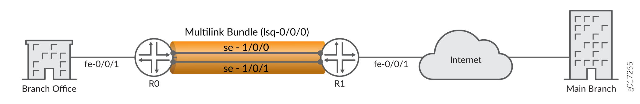
In this example, you create the MLPPP bundle lsq-0/0/0.0 at the logical unit level of the link services interface lsq-0/0/0 on Juniper Networks devices R0 and R1. You then add the two serial interfaces se-1/0/0 and se-1/0/1 as constituent links to the multilink bundle. In Figure 1, your company's branch office is connected to its main branch using devices R0 and R1. You transmit data and voice traffic on two low-speed 1-Mbps serial links. To increase bandwidth, you configure MLPPP and join the two serial links se-1/0/0 and se-1/0/1 into the multilink bundle lsq-0/0/0.0. Then configure LFI and CoS on R0 and R1 to enable the routers to transmit voice packets ahead of data packets.
Configuration
Procedure
CLI Quick Configuration
To quickly configure this example, copy the following command and paste into a text file. Remove
any line breaks. Change any details necessary to match your network
configuration. Copy and paste the command into the CLI at the
[edit] hierarchy level. Enter commit
from configuration mode.
For device R0
set interfaces lsq-0/0/0 unit 0 family inet address 10.0.0.10/24
set interfaces se-1/0/0 unit 0 family mlppp bundle lsq-0/0/0.0
set interfaces se-1/0/1 unit 0 family mlppp bundle lsq-0/0/0.0
set interfaces se-1/0/0 serial-options clocking-mode dce clock-rate 2.0mhz
set interfaces se-1/0/1 serial-options clocking-mode dce clock-rate 2.0mhz
For device R1
set interfaces lsq-0/0/0 unit 0 family inet address 10.0.0.9/24
set interfaces se-1/0/0 unit 0 family mlppp bundle lsq-0/0/0.0
set interfaces se-1/0/1 unit 0 family mlppp bundle lsq-0/0/0.0
Step-by-Step Procedure
The following example requires you to navigate various levels in the configuration hierarchy. For instructions on how to do that, see Using the CLI Editor in Configuration Mode.
To configure MLPPP bundle:
Create an interface on both devices.
[edit]
user@host# edit interfaces lsq-0/0/0 unit 0
Configure a family inet and define the IP address on device R0.
[edit interfaces lsq-0/0/0 unit 0]
user@host# set family inet address 10.0.0.10/24
Configure a family inet and define the IP address on device R1.
[edit interfaces lsq-0/0/0 unit 0]
user@host# set family inet address 10.0.0.9/24
Specify the names of the constituent links to be added to the multilink bundle on both devices.
[edit interfaces]
user@host# edit se-1/0/0 unit 0
user@host# set family mlppp bundle lsq-0/0/0.0
[edit interfaces]
user@host# edit se-1/0/1 unit 0
user@host# set family mlppp bundle lsq-0/0/0.0
Set the serial options to the same values for both interfaces on R0.
R0 is set as a DCE device. The serial options are not set for interfaces on R1. Set the serial options according to your network setup.
[edit interfaces]
user@host# set se-1/0/0 serial-options clocking-mode dce clock-rate 2.0mhz
user@host# set se-1/0/1 serial-options clocking-mode dce clock-rate 2.0mhz
Results
From configuration mode, confirm your configuration
by entering the show interfaces lsq-0/0/0, show interfaces
se-1/0/0, and show interfaces se-1/0/1 commands for
R0 and R1. If the output does not display the intended configuration,
repeat the configuration instructions in this example to correct it.
For device R0
[edit]
    user@host# show interfaces lsq-0/0/0
family inet {
    address 10.0.0.10/24;
        }
    }
[edit]
user@host# show interfaces se-1/0/0
    clocking-mode dce;
        clock-rate 2.0mhz;
        }
        unit 0 {
            family mlppp {
            bundle lsq-0/0/0.0;
        }
    }
[edit]
    user@host# show interfaces se-1/0/1
serial-options {
    clocking-mode dce;
        clock-rate 2.0mhz;
        }
        unit 0 {
            family mlppp {
            bundle lsq-0/0/0.0;
        }
    }
For device R1 [edit] user@host#show interfaces lsq-0/0/0family inet { address 10.0.0.9/24; } } [edit] user@host#show interfaces se-1/0/0unit 0 { family mlppp { bundle lsq-0/0/0.0; } } [edit] user@host#show interfaces se-1/0/1unit 0 { family mlppp { bundle lsq-0/0/0.0; } }
If you are done configuring the device, enter commit from configuration mode.