LTE Mini Physical Interface Modules (LTE Mini-PIM)
Learn about the LTE MIni-PIM, the features supported on it, and how to configure it on security devices.
LTE Mini-PIM Overview
The LTE Mini-Physical Interface Module (Mini-PIM) provides wireless WAN support on security devices. Table 1 specifies the key details of the LTE Mini-PIM interface.
Interface Details |
Descriptions |
|---|---|
Interface name |
LTE Mini-PIM |
Supported on |
For information about platforms support, see hardware compatibility tool (HCT). |
Models |
See LTE Mini-PIM Models. |
Physical interface for the 4GbE LTE Mini-PIM |
|
Key deployment |
|
For hardware specifications for the LTE Mini-PIM, see LTE Mini-Physical Interface Module.
Features Supported on the LTE Mini-PIM
Table 2 describes the key features supported on LTE Mini-PIM.
Feature |
Description |
|---|---|
Automatic switchover between service providers through dual SIMs |
Supports dual Subscriber Identity Module (SIM) cards that allow connectivity to two different ISP networks. Automatic switchover provides a failover mechanism when the current active network fails. |
Multiple service provider and Access Point Name (APN) profiles |
Supports up to 16 profiles configuration for each SIM. The LTE Mini-PIM supports two SIM cards, you can configure a total of 32 profiles and at a time, only single profile is active. |
SIM security functions |
Supports security functions such as SIM lock and unlock, and PIN change. |
Primary, logical and backup interface with always-on, dial-on-demand, and backup modes |
On receiving traffic, the logical dl0 interface enables and places calls through the physical interface in the dialer pool. The dialer interface performs backup and dialer filter functions. You can configure the dialer interface to operate as:
Configuration modes: always-on, dial-on-demand or backup modes. You can configure the Mini-PIM in any one of the modes.
|
Over-the-air upgrade for modem firmware |
Supports Over-the-air (OTA) firmware upgrade that enables automatic and timely upgrade of modem firmware when new firmware versions are available. You can enable or disable the OTA upgrade on the LTE Mini-PIM. OTA upgrade is disabled by default. |
Configure LTE Mini-PIM
Configure the LTE Mini-PIM as a primary interface, as a backup interface or as a dial-on-demand (DOD) interface.
- Configure LTE Mini-PIM as a Primary Interface
- Configure LTE Mini-PIM in a High Availability Cluster Mode
- Configure LTE Mini-PIM as a Backup Interface
- Configure LTE Mini-PIM as a DOD (DOD) Interface
Configure LTE Mini-PIM as a Primary Interface
Before you begin, ensure that dl0.0 is not configured as a backup interface. If dl0.0 is configured as a backup for any interface on the SRX Series Firewall, then this configuration overrides the configuration outlined in this procedure, and the LTE Mini-PIM will function as a backup interface.
Use the show interfaces | display set | match backup-option | match dl0.0
command to check whether any interface uses dl0.0 as a backup interface. If dl0.0 is
configured as a backup interface, then delete the configuration by issuing the following
command: delete interfaces interface-name unit 0 backup-options
interface dl0.0
The LTE Mini-PIM installed on an SRX320 device functions as the primary interface as seen in Figure 1. Assumption is that the LTE Mini-PIM is installed in slot 1 on the SRX320 devices.
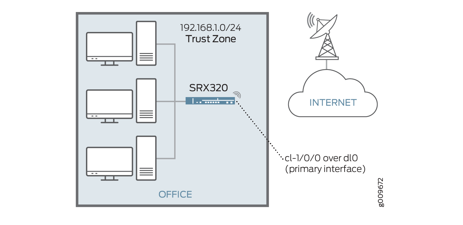
To configure the LTE Mini-PIM as a primary interface:
Configure LTE Mini-PIM in a High Availability Cluster Mode
An SRX chassis cluster supports two cl interfaces, cl-1/1/0 (primary node) and cl-8/1/0 (secondary
node).
To configure the LTE Mini-PIM in a high availability cluster mode:
Configure LTE Mini-PIM as a Backup Interface
You can configure the LTE Mini-PIM as a backup interface. If the primary interface fails, the LTE
Mini-PIM connects to the network and remains online only until the primary interface
becomes functional. The dialer interface is enabled only when the primary interface fails.
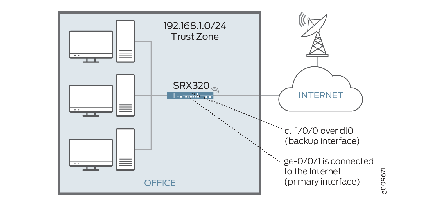
LTE Mini-PIM installed on SRX320 and functions as a backup interface as shown in Figure 2.
The ge-0/0/1 port is connected to the Internet and functions as the
primary interface. In this scenario, the Mini-PIM is installed on slot 1.
To configure the LTE Mini-PIM as a backup interface:
You can use the activation-delay and deactivation-delay
command-line options to avoid interface flaps. Avoid the Interface flaps by forcing a
delay between the time the primary interface changes states, and the time the dialer
interface is enabled or disabled. The activation delay controls the time between the
primary interface going down and activation of the dialer interface. Similarly, the
deactivation delay controls the time between the recovery of the primary interface and
deactivation of the backup interface.
You can insert the SIM of another LTE provider in the second SIM slot if the active SIM has an issue (for example, weak signal). The second SIM now becomes the active SIM.
The switchover between the two SIMs is automatic and no manual control is involved. This automatic switchover only happens when the active SIM has an issue such as weak signal. The active SIM tries to re-connect 3 times and in case of failure, the other SIM becomes active and starts connecting.
Configure LTE Mini-PIM as a DOD (DOD) Interface
When you configure the LTE interface as a primary interface, it functions either in always-on or in DOD mode. In always-on mode, the interface remains connected to the network whereas in DOD mode, the connection is established only when needed.
In DOD mode, you can enable the dialer interface only when network traffic configured as an “interesting traffic” arrives on the network. Interesting traffic triggers or activates the wireless WAN connection. You define an interesting packet by using the dialer filter. To configure DOD by using a dialer filter, you first configure the dialer filter and then apply the filter to the dialer interface. Once the traffic is sent over the network, an inactivity timer is triggered, and the connection is closed after the timer expires. The DOD mode is supported only if the LTE Mini-PIM is configured as a primary interface.
The LTE Mini-PIM installed on an SRX320 functions as the primary interface as show in Figure 3 and assumed that the LTE Mini-PIM is installed in slot 1 on the device.
To configure the LTE Mini-PIM as a DOD interface:
Example: Configure LTE Mini-PIM as a Backup Interface
This example shows how to configure the LTE Mini-PIM as a backup interface. If the primary interface fails, the Mini-PIM connects to the network and remains online only until the primary interface becomes functional. The dialer interface is enabled only when the primary interface fails. In this scenario, the Mini-PIM is installed on slot 1.
Requirements
Overview
Configuration
CLI Quick Configuration
To quickly configure this example, copy the
following command, paste it into a text file, remove any line breaks,
change any details necessary to match your network configuration,
copy and paste the command into the CLI at the [edit] hierarchy
level, and then enter commit from configuration mode.
set interfaces dl0 unit 0 family inet negotiate-address set interfaces dl0 unit 0 family inet6 negotiate-address set interfaces dl0 unit 0 dialer-options pool dialer-pool-number set interfaces dl0 unit 0 dialer-options dial-string dial-number set interfaces cl-1/0/0 dialer-options pool dialer-pool-number run request modem wireless create-profile profile-id profile-id cl-1/0/0 slot sim-slot-number access-point-name l3vpn.corp authentication-method none run show modem wireless profiles cl-1/0/0 slot 1 set interfaces cl-1/0/0 act-sim sim-slot-number set interfaces cl-1/0/0 cellular-options sim sim-slot-number select-profile profile-id profile-id set interfaces cl-1/0/0 cellular-options sim sim-slot-number radio-access automatic set interfaces ge-0/0/1 unit 0 family inet address 192.168.2.1/24 set interfaces ge-0/0/1 unit 0 backup-options interface dl0.0
Configure the LTE Mini-PIM as a Backup Interface
Step-by-Step Procedure
The following example requires you to navigate various levels in the configuration hierarchy. For instructions on how to do that, see Using the CLI Editor in Configuration Mode in the Junos OS CLI User Guide.
To configure LTE Mini-PIM as a backup interface:
Create the dialer interface.
[edit interfaces] user@host# set interfaces dl0 unit 0 family inet negotiate-address user@host# set interfaces dl0 unit 0 family inet6 negotiate-address user@host# set interfaces dl0 unit 0 dialer-options pool dialer-pool-number user@host# set interfaces dl0 unit 0 dialer-options dial-string dial-number
Define the dialer pool for the LTE Mini-PIM physical interface.
user@host# set interfaces cl-1/0/0 dialer-options pool dialer-pool-number
Create and configure the profile on the SIM cards.
sim-slot-numberis the slot on the Mini-PIM in which the SIM card is inserted.user@host# run request modem wireless create-profile profile-id profile-id cl-1/0/0 slot sim-slot-number access-point-name l3vpn.corp authentication-method none
Activate the SIM card.
user@host# set interfaces cl-1/0/0 act-sim sim-slot-number
Select the profile and configure the radio access type for the SIM card.
user@host# set interfaces cl-1/0/0 cellular-options sim sim-slot-number select-profile profile-id profile-id
user@host# set interfaces cl-1/0/0 cellular-options sim sim-slot-number radio-access automatic
Specify Ethernet interface as the primary interface, which connects to the wireless network. Specify the dl0 interface as the backup interface.
user@host# set interfaces ge-0/0/1 unit 0 family inet address 192.168.2.1/24
user@host# set interfaces ge-0/0/1 unit 0 backup-options interface dl0.0
Results
From configuration mode, confirm your configuration
by entering the show interfaces dl0.0 command. If the
output does not display the intended configuration, repeat the configuration
instructions in this example to correct it.
user@host> show interfaces dl0.0
Logical interface dl0.0 (Index 353) (SNMP ifIndex 559)
    Flags: Up Point-To-Point SNMP-Traps 0x4004000 Encapsulation: ENET2
    Dialer:
    State: Active, Dial pool: pool1
    Primary interface: ge-1/0/1.0 (Index 350)
    Dial strings: 1234
    Subordinate interfaces: cl-1/1/0 (Index 161)
    Activation delay: 0, Deactivation delay: 0
    Initial route check delay: 120
    Redial delay: 120
    Callback wait period: 5
    Load threshold: 0, Load interval: 60
    Input packets : 7
    Output packets: 10
    Protocol inet, MTU: 1490
    Max nh cache: 0, New hold nh limit: 0, Curr nh cnt: 0, Curr new hold cnt: 0, NH drop cnt: 0
    Flags: Sendbcast-pkt-to-re, Negotiate-Address
    Addresses, Flags: Is-Preferred Is-Primary
    Destination: 100.100.60.208/29, Local: 100.100.60.212, Broadcast: 100.100.60.215
    Protocol inet6, MTU: 1490
    Max nh cache: 75000, New hold nh limit: 75000, Curr nh cnt: 0, Curr new hold cnt: 0, NH drop cnt: 0
    Flags: Is-Primary, Negotiate-Address
    Addresses, Flags: Is-Preferred
    Destination: fe80::/64, Local: fe80::5a00:bb0f:fcaa:7d00
Verification
- Verification of the configured profile
- Verification of status of the dialer interface
- Verification of status of the modem network and modem firmware
Verification of the configured profile
Purpose
Verify that the profile is configured successfully.
Action
From operational mode, run the show modem wireless
profiles cl-1/0/0 slot 1 command.
user@host> show modem wireless profiles cl-1/0/0 slot 1

Profile details
  Max profiles: 16
  Default profile Id: 1

Profile 1: ACTIVE
  Valid: TRUE
  Access point name (APN): airtelgprs.com
  Authentication: None
  IP Version: IPV4V6
Profile 2: Inactive
  Valid: TRUE
  Access point name (APN): airtelgprs.com
  Authentication: None
  IP Version: IPV4
Profile 3: Inactive
  Valid: TRUE
  Access point name (APN): airtelgprs.com
  Authentication: None
  IP Version: IPV4
Profile 4: Inactive
  Valid: TRUE
  Access point name (APN): airtelgprs.com
  Authentication: None
  IP Version: IPV4
Profile 5: Inactive
  Valid: TRUE
  Access point name (APN): airtelgprs.com
  Authentication: None
  IP Version: IPV4
Profile 6: Inactive
  Valid: TRUE
  Access point name (APN): airtelgprs.com
  Authentication: None
  IP Version: IPV4
Profile 7: Inactive
  Valid: TRUE
  Access point name (APN): airtelgprs.com
  Authentication: None
  IP Version: IPV4
Profile 8: Inactive
  Valid: TRUE
  Access point name (APN): airtelgprs.com
  Authentication: None
  IP Version: IPV4
Profile 9: Inactive
  Valid: TRUE
  Access point name (APN): airtelgprs.com
  Authentication: None
  IP Version: IPV4
Profile 10: Inactive
  Valid: TRUE
  Access point name (APN): airtelgprs.com
  Authentication: None
  IP Version: IPV4
Profile 11: Inactive
  Valid: TRUE
  Access point name (APN): airtelgprs.com
  Authentication: None
  IP Version: IPV4
Profile 12: Inactive
  Valid: TRUE
  Access point name (APN): airtelgprs.com
  Authentication: None
  IP Version: IPV4
Profile 13: Inactive
  Valid: TRUE
  Access point name (APN): airtelgprs.com
  Authentication: None
  IP Version: IPV4
Profile 14: Inactive
  Valid: TRUE
  Access point name (APN): airtelgprs.com
  Authentication: None
  IP Version: IPV4
Profile 15: Inactive
  Valid: TRUE
  Access point name (APN): airtelgprs.com
  Authentication: None
  IP Version: IPV4
Profile 16: Inactive
  Valid: TRUE
  Access point name (APN): airtelgprs.com
  Authentication: None
  IP Version: IPV4
Meaning
The output confirms the profile is active.
Verification of status of the dialer interface
Purpose
Verify that the dialer interface is configured successfully.
Action
From operational mode, run the show interfaces
dl0.0 command.
user@host> show interfaces dl0.0

    Logical interface dl0.0 (Index 353) (SNMP ifIndex 559)
    Flags: Up Point-To-Point SNMP-Traps 0x4004000 Encapsulation: ENET2
    Dialer:
    State: Active, Dial pool: pool1
    Primary interface: ge-1/0/1.0 (Index 350)
    Dial strings: 1234
    Subordinate interfaces: cl-1/1/0 (Index 161)
    Activation delay: 0, Deactivation delay: 0
    Initial route check delay: 120
    Redial delay: 120
    Callback wait period: 5
    Load threshold: 0, Load interval: 60
    Input packets : 7
    Output packets: 10
    Protocol inet, MTU: 1490
    Max nh cache: 0, New hold nh limit: 0, Curr nh cnt: 0, Curr new hold cnt: 0, NH drop cnt: 0
    Flags: Sendbcast-pkt-to-re, Negotiate-Address
    Addresses, Flags: Is-Preferred Is-Primary
    Destination: 100.100.60.208/29, Local: 100.100.60.212, Broadcast: 100.100.60.215
    Protocol inet6, MTU: 1490
    Max nh cache: 75000, New hold nh limit: 75000, Curr nh cnt: 0, Curr new hold cnt: 0, NH drop cnt: 0
    Flags: Is-Primary, Negotiate-Address
    Addresses, Flags: Is-Preferred
    Destination: fe80::/64, Local: fe80::5a00:bb0f:fcaa:7d00
Meaning
The output confirms the interface dlo is
configured and active.
Verification of status of the modem network and modem firmware
Purpose
Verify that the wireless network is configured, check the firmware, and check if the sim is active.
Action
From operational mode, enter the show modem wireless
network cl-1/0/0 command to verify the network status and show modem wireless firmware cl-1/0/0 command to verify the
firmware and sim status. Alternatively you can use the show configuration command to verify the complete status.
user@host> show modem wireless network cl-1/0/0

LTE Connection details
Connected time: 147
IP: 172.16.52.4
Gateway: 172.16.52.5
DNS: 123.123.123.123
Input bps: 0
Output bps: 0
Bytes Received: 1308
Bytes Transferred: 1164
Packets Received: 10
Packets Transferred: 10
Wireless Modem Network Info
Current Modem Status: Connected
Current Service Status: Normal
Current Service Type: PS
Current Service Mode: LTE
Current Band: B3
Network: UNICOM
Mobile Country Code (MCC): 460
Mobile Network Code (MNC): 1
Location Area Code (LAC): 65534
Routing Area Code (RAC): 0
Cell Identification: 4865903
Access Point Name (APN): abcde
Public Land Mobile Network (PLMN): CHN-UNICOM
Physical Cell ID (PCI): 333
International Mobile Subscriber Identification (IMSI): ***************
International Mobile Equipment Identification (IMEI/MEID): ***************
Integrate Circuit Card Identity (ICCID): 89860114721100697502
Reference Signal Receiving Power (RSRP): -97
Reference Signal Receiving Quality (RSRQ): -16
Signal to Interference-plus-Noise Ratio (SiNR): 0
Signal Noise Ratio (SNR): 0
Energy per Chip to Interference (ECIO): 0
Meaning
The output here shows the wireless modem network is connected and IP address of the firmware connected.