Examples: Bundling Multiple PPP Links on a Single Link Using MLPPP
Example: Configuring a Multilink Interface with MLPPP
[edit interfaces]
ml-1/0/0 {
    unit 1 {
        fragment-threshold 128;
        family inet {
            address 192.168.5.1/32 {
                destination 192.168.200.200;
            }
        }
    }
    unit 10 {
        family inet {
            address 10.1.1.3/32 {
                destination 10.1.1.2;
            }
        }
    }
}
t1-5/1/0 {
    unit 0 {
        family mlppp {
            bundle ml-1/0/0.1;
        }
    }
}
t1-5/1/1 {
    unit 0 {
        family mlppp {
            bundle ml-1/0/0.1;
        }
    }
}
t1-5/1/2 {
    unit 0 {
        family mlppp {
            bundle ml-1/0/0.1;
        }
    }
}
See Also
Example: Configuring a Multilink Interface with MLPPP over ATM 2 Interfaces
[edit interfaces]
at-0/0/0 {
    atm-options {
        pic-type atm2;
        vpi 10;
    }
    unit 0 {
        encapsulation atm-mlppp-llc;
        ppp-options {
            chap {
                access-profile pe-B-ppp-clients;
                local-name “pe-A-at-0/0/0”;
            }
        }
        keepalive interval 5 up-count 6 down-count 4;
        vci 10.120;
        family mlppp {
            bundle ls-0/3/0.0;
        }
    }
}
at-0/0/1 {
    atm-options {
        pic-type atm2;
        vpi 11;
    }
    unit 1 {
        encapsulation atm-mlppp-llc;
        ppp-options {
            chap {
                access-profile pe-B-ppp-clients;
                local-name “ pe-A-at-0/0/0”;
            }
        }
        keepalive interval 5 up-count 6 down-count 4;
        vci 11.120;
        family mlppp {
            bundle ls-0/3/0.0;
        }
    }
}
at-1/2/3 {
    atm-options {
        pic-type atm2;
        vpi 12;
    }
    unit 2 {
        encapsulation atm-mlppp-llc;
        ppp-options {
            chap {
                access-profile pe-B-ppp-clients;
                local-name “ pe-A-at-0/0/0”;
            }
        }
        keepalive interval 5 up-count 6 down-count 4;
        vci 12.120;
        family mlppp {
            bundle ls-0/3/0.0;
        }
    }
}
...
ls-0/3/0 {
    encapsulation multilink-ppp;
    interleave-fragments;
    keepalive;
    unit 0 {
        mrru 4500;
        short-sequence;
        fragment-threshold 16320;
        drop-timeout 2000;
        encapsulation multilink-ppp;
        interleave-fragments;
        minimum-links 8;
        family inet {
            address 10.10.0.1/32 {
                destination 10.10.0.2;
            }
        }
        family iso;
        family inet6 {
            address 2001:DB8::0:1/32 {
                destination 2001:DB8::0:2;
            }
        }
    }
    ...
}
See Also
Example: Configuring an MLPPP Bundle
This example shows how to configure an MLPPP bundle to increase traffic bandwidth.
Requirements
Before you begin, you should have two MX Series routers (MX240, MX480, or MX960 routers) configured with at least two serial interfaces that communicate over serial links.
Overview
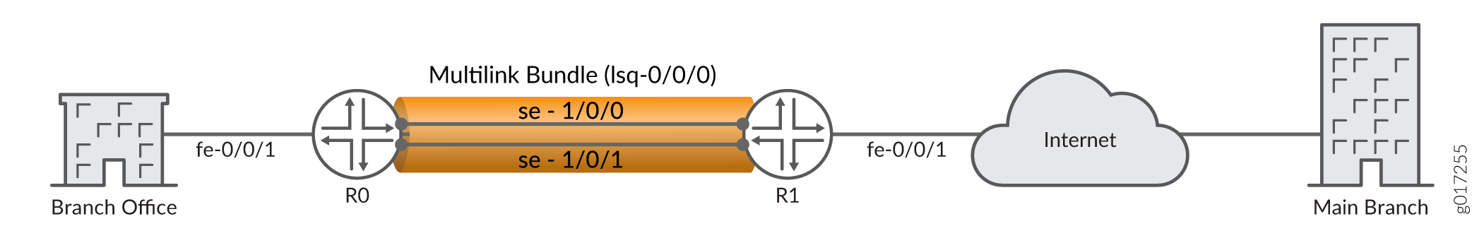
In this example, you create the MLPPP bundle lsq-0/0/0.0 at the logical unit level of the link services interface lsq-0/0/0 on the MX Series routers R0 and R1. You then add the two serial interfaces se-1/0/0 and se-1/0/1 as constituent links to the multilink bundle. In Figure 1, your company's branch office is connected to its main branch using routers R0 and R1. You transmit data and voice traffic on two low-speed 1-Mbps serial links. To increase bandwidth, you configure MLPPP and join the two serial links se-1/0/0 and se-1/0/1 into the multilink bundle lsq-0/0/0.0. Then you configure LFI and CoS on R0 and R1 to enable them to transmit voice packets ahead of data packets.
Configuration
Procedure
CLI Quick Configuration
To quickly configure this example, copy the
following commands, paste them into a text file, remove any line breaks,
change any details necessary to match your network configuration,
and then copy and paste the commands into the CLI at the [edit] hierarchy level.
For device R0
set interfaces lsq-0/0/0 unit 0 family inet address 10.0.0.10/24
set interfaces se-1/0/0 unit 0 family mlppp bundle lsq-0/0/0.0
set interfaces se-1/0/1 unit 0 family mlppp bundle lsq-0/0/0.0
set interfaces se-1/0/0 serial-options clocking-mode dce clock-rate 2.0mhz
set interfaces se-1/0/1 serial-options clocking-mode dce clock-rate 2.0mhz
For device R1
set interfaces lsq-0/0/0 unit 0 family inet address 10.0.0.9/24
set interfaces se-1/0/0 unit 0 family mlppp bundle lsq-0/0/0.0
set interfaces se-1/0/1 unit 0 family mlppp bundle lsq-0/0/0.0
Step-by-Step Procedure
The following example requires you to navigate various levels in the configuration hierarchy. For instructions on how to do that, see Using the CLI Editor in Configuration Mode in the Junos OS CLI User Guide.
To configure MLPPP bundle:
Create an interface on both the routers.
[edit]
user@host# edit interfaces lsq-0/0/0 unit 0
Configure a family inet and define the IP address on device R0.
[edit interfaces lsq-0/0/0 unit 0]
user@host# set family inet address 10.0.0.10/24
Configure a family inet and define the IP address on device R1.
[edit interfaces lsq-0/0/0 unit 0]
user@host# set family inet address 10.0.0.9/24
Specify the names of the constituent links to be added to the multilink bundle on both the routers.
[edit interfaces]
user@host# edit se-1/0/0 unit 0
user@host# set family mlppp bundle lsq-0/0/0.0
[edit interfaces]
user@host# edit se-1/0/1 unit 0
user@host# set family mlppp bundle lsq-0/0/0.0
Set the serial options to the same values for both interfaces on R0.
Note:R0 is set as a DCE device. The serial options are not set for interfaces on R1. You can set the serial options according to your network setup.
[edit interfaces]
user@host# set se-1/0/0 serial-options clocking-mode dce clock-rate 2.0mhz
user@host# set se-1/0/1 serial-options clocking-mode dce clock-rate 2.0mhz
Results
From configuration mode, confirm your configuration
by entering the show interfaces lsq-0/0/0, show interfaces
se-1/0/0, and show interfaces se-1/0/1 commands for
R0 and R1. If the output does not display the intended configuration,
repeat the configuration instructions in this example to correct it.
For device R0
[edit]
    user@host# show interfaces lsq-0/0/0
family inet {
    address 10.0.0.10/24;
        }
    }
[edit]
user@host# show interfaces se-1/0/0
    clocking-mode dce;
        clock-rate 2.0mhz;
        }
        unit 0 {
            family mlppp {
            bundle lsq-0/0/0.0;
        }
    }
[edit]
    user@host# show interfaces se-1/0/1
serial-options {
    clocking-mode dce;
        clock-rate 2.0mhz;
        }
        unit 0 {
            family mlppp {
            bundle lsq-0/0/0.0;
        }
    }
For device R1 [edit] user@host#show interfaces lsq-0/0/0family inet { address 10.0.0.9/24; } } [edit] user@host#show interfaces se-1/0/0unit 0 { family mlppp { bundle lsq-0/0/0.0; } } [edit] user@host#show interfaces se-1/0/1unit 0 { family mlppp { bundle lsq-0/0/0.0; } }
If you are done configuring the router, enter commit from configuration mode.
Example: Configuring a Link Services Interface with MLPPP
[edit interfaces]
t1-0/0/0 {
    encapsulation ppp;
    unit 0 {
        family mlppp {
            bundle ls-0/3/0.0;
        }
    }
}
t1-0/0/1 {
    encapsulation ppp;
    unit 0 {
        family mlppp {
            bundle ls-0/3/0.0;
        }
    }
}
ls-0/3/0 {
    unit 0 {
        encapsulation multilink-ppp;
        family inet {
            address 10.16.1.2/32 {
                destination 10.16.1.1;
            }
        }
        family iso;
        family inet6 {
            address 2001:DB8::1:2/126;
        }
    }
}
See Also
Example: Configuring Inline MLPPP and Multilink Frame Relay End-to-End (FRF.15) for WAN Interfaces
Inline Multilink PPP (MLPPP), Multlink Frame Relay (FRF.16), and Multilink Frame Relay End-to-End (FRF.15) for time-division multiplexing (TDM) WAN interfaces provide bundling services through the Packet Forwarding Engine without requiring a PIC or Dense Port Concentrator (DPC).
This example shows how to configure a Multilink PPP (MLPPP) bundle and Multilink Frame Relay End-to-End (FRF.15) for additional bandwidth, load balancing, and redundancy by aggregating low-speed links such as T1 (WAN interfaces).
Requirements
This example uses the following hardware and software components:
Two MX Series Routers
Junos OS Release 14.1 or later release
Before you begin, configure two MX Series routers (the MX240, MX480, or MX960) with at least two WAN interfaces that communicate over T1 links.
Overview
Traditionally, bundling services are used to bundle multiple low-speed links to create a higher bandwidth pipe. This combined bandwidth is available to traffic from all links and supports link fragmentation and interleaving (LFI) on the bundle, reducing high-priority packet transmission delay.
This support includes multiple links on the same bundle as well as multiclass extension for MLPPP. Through this service you can enable bundling services without additional DPC slots to support Service DPC and free up the slots for other MICs.
Configuring inline MLPPP for WAN interfaces benefits the following services:
CE-PE link for Layer 3 VPN and DIA service with public switched telephone networks (PSTN)-based access networks
PE-P link when PSTN is used for MPLS networks
In this example, to increase bandwidth, you configure MLPPP
and join the T1 links into the multilink bundle. You aggregate T1
links to create the MLFR FRF.15 bundle on two MX Series routers, R0
and R1, and set the interface to lsq-. You configure logical
units on the lsq- interface and set the family type to inet and an IP address. Then you configure an IP address for
the multilink bundle on the unit level of the interface. You define
the multilink bundle as an MLFR FRF.15 bundle by specifying the MLFR
end-to-end encapsulation type. You specify the names of the constituent
links to be added to the multilink bundle and set the encapsulation
type to frame-relay. You then define Router R0 as a DCE
device and Router R1 as a DTE device. You set the DLCI value (range
is from 16 through 1022). Finally, you set the multilink bundle to lsq-.
Topology
Configuration
CLI Quick Configuration
To quickly configure this example, copy the
following commands, paste them into a text file, remove any line breaks,
change any details necessary to match your network configuration,
and then copy and paste the commands into the CLI at the [edit] hierarchy level.
Device R0
set chassis fpc 1 pic 0 multi-link-layer-2-inline
set interfaces lsq-1/0/0 unit 0 encapsulation multilink-ppp
set interfaces lsq-1/0/0 unit 0 family inet address 192.0.2.1/24
set interfaces lsq-1/0/0 unit 1 encapsulation multilink-frame-relay-end-to-end
set interfaces lsq-1/0/0 unit 1 family inet address 198.51.100.1/24
set interfaces t1-1/0/0:1 unit 0 family mlppp bundle lsq-1/0/0.0
set interfaces t1-1/0/0:2 unit 0 family mlppp bundle lsq-1/0/0.0
set interfaces t1-1/0/0:3 dce
set interfaces t1-1/0/0:4 dce
set interfaces t1-1/0/0:3 encapsulation frame-relay
set interfaces t1-1/0/0:4 encapsulation frame-relay
set interfaces t1-1/0/0:3 unit 0 dlci 1 family mlfr-end-to-end bundle lsq-1/0/0.1
set interfaces t1-1/0/0:4 unit 0 dlci 2 family mlfr-end-to-end bundle lsq-1/0/0.1
Device R1
set chassis fpc 2 pic 0 multi-link-layer-2-inline
set interfaces lsq-2/0/0 unit 0 encapsulation multilink-ppp
set interfaces lsq-2/0/0 unit 0 family inet address 192.0.2.2/24
set interfaces lsq-2/0/0 unit 1 encapsulation multilink-frame-relay-end-to-end
set interfaces lsq-2/0/0 unit 1 family inet address 198.51.100.2/24
set interfaces t1-2/0/0:1 unit 0 family mlppp bundle lsq-2/0/0.0
set interfaces t1-2/0/0:2 unit 0 family mlppp bundle lsq-2/0/0.0
set interfaces t1-2/0/0:3 encapsulation frame-relay
set interfaces t1-2/0/0:4 encapsulation frame-relay
set interfaces t1-2/0/0:3 unit 0 dlci 1 family mlfr-end-to-end bundle lsq-2/0/0.1
set interfaces t1-2/0/0:4 unit 0 dlci 2 family mlfr-end-to-end bundle lsq-2/0/0.1
To Configure Router R0
Step-by-Step Procedure
The following example requires you to navigate various levels in the configuration hierarchy. For information about navigating the CLI, see Using the CLI Editor in Configuration Mode in the Junos OS CLI User Guide.
To configure inline MLPPP and Multilink Frame Relay End-to-End (FRF.15) for WAN Interfaces:
Enable inline Layer 2 bundling services.
[edit]
user@R0# set chassis fpc 1 pic 0 multi-link-layer-2-inline
Create the interface, specify a logical unit on the multilink bundle, and set the family type.
[edit]
user@R0# set interfaces lsq-1/0/0 unit 0 family inet address 192.0.2.1/24
Specify the encapsulation type as MLPPP.
[edit]
user@R0# set interfaces lsq-1/0/0 unit 0 encapsulation multilink-ppp
Create the interface, specify another logical unit on the multilink bundle, and set the family type.
[edit]
user@R0# set interfaces lsq-1/0/0 unit 1 family inet address 198.51.100.1/24
Specify another unit and define the multilink bundle as an MLFR FRF.15 bundle.
[edit]
user@R0# set interfaces lsq-1/0/0 unit 1 encapsulation multilink-frame-relay-end-to-end
Specify the names of the constituent links to be added to the multilink bundle.
[edit]
user@R0# set interfaces t1-1/0/0:1 unit 0 family mlppp bundle lsq-1/0/0.0
user@R0# set interfaces t1-1/0/0:2 unit 0 family mlppp bundle lsq-1/0/0.0
Define the router as a DCE device.
[edit]
user@R0# set interfaces t1-1/0/0:3 dce
user@R0# set interfaces t1-1/0/0:4 dce
Specify the DLCI as well as the multilink bundle to which the interface is to be added.
[edit ]
user@R0# set interfaces t1-1/0/0:3 unit 0 dlci 1 family mlfr-end-to-end bundle lsq-1/0/0.1
user@R0# set interfaces t1-1/0/0:4 unit 0 dlci 2 family mlfr-end-to-end bundle lsq-1/0/0.1
Specify the names of the constituent links to be added to the multilink bundle.
[edit]
user@R0# set interfaces t1-1/0/0:3 encapsulation frame-relay
user@R0# set interfaces t1-1/0/0:4 encapsulation frame-relay
To Configure Router R1
Step-by-Step Procedure
To configure inline MLPPP and Multilink Frame Relay End-to-End (FRF.15) for WAN Interfaces:
Enable inline Layer 2 bundling services.
[edit]
user@R1# set chassis fpc 2pic 0 multi-link-layer-2-inline
Create the interface, specify a logical unit on the multilink bundle and set the family type.
[edit]
user@R1# set interfaces lsq-2/0/0 unit 0 family inet address 192.0.2.2/24
Specify the encapsulation type as MLPPP.
[edit]
user@R1# set interfaces lsq-2/0/0 unit 0 encapsulation multilink-ppp
Create the interface, specify another logical unit on the multilink bundle and set the family type.
[edit]
user@R1# set interfaces lsq-2/0/0 unit 1 family inet address 198.51.100.2/24
Specify another unit and define the multilink bundle as an MLFR FRF.15 bundle.
[edit]
user@R1# set interfaces lsq-2/0/0 unit 1 encapsulation multilink-frame-relay-end-to-end
Specify the names of the constituent links to be added to the multilink bundle.
[edit]
user@R1# set interfaces t1-2/0/0:1 unit 0 family mlppp bundle lsq-2/0/0.0
user@R1# set interfaces t1-2/0/0:2 unit 0 family mlppp bundle lsq-2/0/0.0
Specify the DLCI as well as the multilink bundle to which the interface is to be added.
[edit ]
user@R1# set interfaces t1-2/0/0:3 unit 0 dlci 1 family mlfr-end-to-end bundle lsq-2/0/0.1
user@R1# set interfaces t1-2/0/0:4 unit 0 dlci 2 family mlfr-end-to-end bundle lsq-2/0/0.1
Specify the names of the constituent links to be added to the multilink bundle.
[edit]
user@R1# set interfaces t1-2/0/0:3 encapsulation frame-relay
user@R1# set interfaces t1-2/0/0:4 encapsulation frame-relay
Results
For Router R0, from configuration mode, confirm your
configuration by entering the show chassis, show interfaces
lsq-1/0/0, show interfaces t1-1/0/0:1, show
interfaces t1-1/0/0:2, show interfaces t1-1/0/0:3, and show interfaces t1-1/0/0:4 commands.
For Router R1, from configuration mode, confirm your configuration
by entering the show chassis, show interfaces lsq-2/0/0, show interfaces t1-2/0/0:1, show interfaces t1-2/0/0:2, show interfaces t1-2/0/0:3, and show interfaces
t1-2/0/0:4 commands.
If the output does not display the intended configuration, repeat the instructions in this example to correct the configuration.
For Router R0:
[edit]
user@R0# show chassis
fpc 1 {
    pic 0 {
        multi-link-layer-2-inline;
    }
}
[edit]
user@R0# show interfaces lsq-1/0/0
unit 0 {
    encapsulation multilink-ppp;
    family inet {
        address 192.0.2.1/24;
    }
}
unit 1 {
    encapsulation multilink-frame-relay-end-to-end;
    family inet {
        address 198.51.100.1/24;
    }
}
[edit]
user@R0# show interfaces t1-1/0/0:1
unit 0 {
    family mlppp {
        bundle lsq-1/0/0.0;
    }
}
[edit]
user@R0# show interfaces t1-1/0/0:2
unit 0 {
    family mlppp {
        bundle lsq-1/0/0.0;
    }
}
[edit]
user@R0# show interfaces t1-1/0/0:3
dce;
encapsulation frame-relay;
unit 0 {
    dlci 1;
    family mlfr-end-to-end {
        bundle lsq-1/0/0.1;
    }
}
[edit]
user@R0# show interfaces t1-1/0/0:4
dce;
encapsulation frame-relay;
unit 0 {
    dlci 2;
    family mlfr-end-to-end {
        bundle lsq-1/0/0.1;
    }
}
If you are done configuring the router, enter commit from configuration mode.
For Router R1:
[edit]
user@R1# show chassis
fpc 2{
    pic 0 {
        multi-link-layer-2-inline;
    }
}
[edit]
user@R1# show interfaces lsq-2/0/0
unit 0 {
    encapsulation multilink-ppp;
    family inet {
        address 192.0.2.2/24;
    }
}
unit 1 {
    encapsulation multilink-frame-relay-end-to-end;
    family inet {
        address 198.51.100.2/24;
    }
}
[edit]
user@R1# show interfaces t1-2/0/0:1
unit 0 {
    family mlppp {
        bundle lsq-2/0/0.0;
    }
}
[edit]
user@R1# show interfaces t1-2/0/0:2
unit 0 {
    family mlppp {
        bundle lsq-2/0/0.0;
    }
}
[edit]
user@R1# show interfaces t1-2/0/0:3
encapsulation frame-relay;
unit 0 {
    dlci 1;
    family mlfr-end-to-end {
        bundle lsq-2/0/0.1;
    }
}
[edit]
user@R1# show interfaces t1-2/0/0:4
encapsulation frame-relay;
unit 0 {
    dlci 2;
    family mlfr-end-to-end {
        bundle lsq-2/0/0.1;
    }
}
If you are done configuring the router, enter commit from configuration mode.
Verification
Verifying the MLPPP Bundle and the MLFR FRF.15 Configuration
Purpose
Verify that the constituent links are added to the bundle correctly.
Action
From operational mode, run the show interfaces
lsq-1/0/0 extensive command.
Sample Output
command-name
user@R0> show interfaces lsq-1/0/0:0 extensive
Physical interface: lsq-1/0/0, Enabled, Physical link is Up
  Interface index: 292, SNMP ifIndex: 1065, Generation: 4986
  Link-level type: LinkService, MTU: 1504
  Device flags   : Present Running
  Interface flags: Point-To-Point SNMP-Traps Internal: 0x4000
  Last flapped   : Never
  Statistics last cleared: Never
  Traffic statistics:
   Input  bytes  :                    0                    0 bps
   Output bytes  :                    0                    0 bps
   Input  packets:                    0                    0 pps
   Output packets:                    0                    0 pps
   IPv6 transit statistics:
    Input  bytes  :                   0
    Output bytes  :                   0
    Input  packets:                   0
    Output packets:                   0
  Frame exceptions:
    Oversized frames                  0
    Errored input frames              0
    Input on disabled link/bundle     0
    Output for disabled link/bundle   0
    Queuing drops                     0
  Buffering exceptions:
    Packet data buffer overflow       0
    Fragment data buffer overflow     0
  Assembly exceptions:
    Fragment timeout                  0
    Missing sequence number           0
    Out-of-order sequence number      0
    Out-of-range sequence number      0
  Hardware errors (sticky):
    Data memory error                 0
    Control memory error              0
  Egress queues: 8 supported, 4 in use
  Queue counters:       Queued packets  Transmitted packets      Dropped packets
    0                                0                    0                    0
    1                                0                    0                    0
    2                                0                    0                    0
    3                                0                    0                    0
  Queue number:         Mapped forwarding classes
    0                   best-effort
    1                   expedited-forwarding
    2                   assured-forwarding
    3                   network-control

  Logical interface lsq-1/0/0.0 (Index 327) (SNMP ifIndex 113518) (Generation 6213)
    Flags: Hardware-Down Up Point-To-Point SNMP-Traps 0x4000 Encapsulation: Multilink-PPP
    Last flapped: 2014-04-24 04:37:39 PDT (00:08:50 ago)
    Bandwidth: 0
    Bundle links information:
      Active bundle links       0
      Removed bundle links      2
      Disabled bundle links     0
    Bundle options:
      MRRU                                 1504
      Remote MRRU                          N/A
      Drop timer period                    32767
      Inner PPP Protocol field compression enabled
      Sequence number format               long (24 bits)
      Fragmentation threshold              0
      Links needed to sustain bundle       1
      Multilink classes                    0
      Link layer overhead                  4.0 %
    Multilink class 0 status:
      Received sequence number        0x0
      Transmit sequence number        0xffffffff
      Packet drops                    0 (0 bytes)
      Fragment drops                  0 (0 bytes)
      MRRU exceeded                   0
      Fragment timeout                0
      Missing sequence number         0
      Out-of-order sequence number    0
      Out-of-range sequence number    0
      Packet data buffer overflow     0
      Fragment data buffer overflow   0
      Multilink class drop timeout    0 (ms)
    Statistics         Frames        fps         Bytes          bps
    Bundle:
      Multilink:
        Input :             0          0             0            0
        Output:             0          0             0            0
      Network:
        Input :             0          0             0            0
        Output:             0          0             0            0
    IPV6 Transit Statistics         Packets        Bytes
      Network:
        Input :                      0               0
        Output:                      0               0
    Link:
      t1-1/0/0:1.0
        Up time: 00:00:00
        Input :             0          0             0            0
        Output:             0          0             0            0
      t1-1/0/0:2.0
        Up time: 00:00:00
        Input :             0          0             0            0
        Output:             0          0             0            0
    Multilink detail statistics:
    Bundle:
      Fragments:
        Input :             0          0             0            0
        Output:             0          0             0            0
      Non-fragments:
        Input :             0          0             0            0
        Output:             0          0             0            0
      LFI:
        Input :             0          0             0            0
        Output:             0          0             0            0
  NCP state: inet: Not-configured, inet6: Not-configured, iso: Not-configured, mpls: Not-configured
    Protocol inet, MTU: 1500, Generation: 6263, Route table: 0
      Flags: Sendbcast-pkt-to-re, Protocol-Down
      Addresses, Flags: Dest-route-down Is-Preferred Is-Primary
        Destination: 192.0.2/24, Local: 192.0.2.1, Broadcast: Unspecified, Generation: 4211

  Logical interface lsq-1/0/0.1 (Index 328) (SNMP ifIndex 113519) (Generation 6214)
    Flags: Up Point-To-Point SNMP-Traps 0x4000 Encapsulation: Multilink-FR
    Last flapped: 2014-04-24 04:46:00 PDT (00:00:29 ago)
    Bandwidth: 3072kbps
    Bundle links information:
      Active bundle links       2
      Removed bundle links      0
      Disabled bundle links     0
    Bundle options:
      MRRU                                 1504
      Drop timer period                    32767
      Inner PPP Protocol field compression enabled
      Sequence number format               short (12 bits)
      Fragmentation threshold              0
      Links needed to sustain bundle       1
      Multilink classes                    0
      Link layer overhead                  4.0 %
    Multilink class 0 status:
      Received sequence number        0x0
      Transmit sequence number        0xffffffff
      Packet drops                    0 (0 bytes)
      Fragment drops                  0 (0 bytes)
      MRRU exceeded                   0
      Fragment timeout                0
      Missing sequence number         0
      Out-of-order sequence number    0
      Out-of-range sequence number    0
      Packet data buffer overflow     0
      Fragment data buffer overflow   0
      Multilink class drop timeout    0 (ms)
    Statistics         Frames        fps         Bytes          bps
    Bundle:
      Multilink:
        Input :             0          0             0            0
        Output:             0          0             0            0
      Network:
        Input :             0          0             0            0
        Output:             0          0             0            0
    Link:
      t1-1/0/0:3.0
        Up time: 00:00:29
        Input :             0          0             0            0
        Output:             0          0             0            0
      t1-1/0/0:4.0
        Up time: 00:00:29
        Input :             0          0             0            0
        Output:             0          0             0            0
    Multilink detail statistics:
    Bundle:
      Fragments:
        Input :             0          0             0            0
        Output:             0          0             0            0
      Non-fragments:
        Input :             0          0             0            0
        Output:             0          0             0            0
      LFI:
        Input :             0          0             0            0
        Output:             0          0             0            0
    Protocol inet, MTU: 1500, Generation: 6264, Route table: 0
      Flags: Sendbcast-pkt-to-re
      Addresses, Flags: Is-Preferred Is-Primary
        Destination: 198.51.100/24, Local: 198.51.100.1, Broadcast: Unspecified, Generation: 4213
From the operational mode, enter the show interfaces lsq-2/0/0
extensive command.
user@R1> show interfaces lsq-2/0/0 extensive
Physical interface: lsq-2/0/0, Enabled, Physical link is Up
  Interface index: 262, SNMP ifIndex: 44421, Generation: 270
  Encapsulation: Multilink-PPPLink-level type: LinkService, MTU: 1504
  Device flags   : Present Running
  Interface flags: Point-To-Point SNMP-Traps Internal: 0x4000
  Last flapped   : Never
  Statistics last cleared: Never
  Traffic statistics:
   Input  bytes  :                    0                    0 bps
   Output bytes  :                    0                    0 bps
   Input  packets:                    0                    0 pps
   Output packets:                    0                    0 pps
   IPv6 transit statistics:
    Input  bytes  :                   0
    Output bytes  :                   0
    Input  packets:                   0
    Output packets:                   0
  Frame exceptions:
    Oversized frames                  0
    Errored input frames              0
    Input on disabled link/bundle     0
    Output for disabled link/bundle   0
    Queuing drops                     0
  Buffering exceptions:
    Packet data buffer overflow       0
    Fragment data buffer overflow     0
  Assembly exceptions:
    Fragment timeout                  0
    Missing sequence number           0
    Out-of-order sequence number      0
    Out-of-range sequence number      0
  Hardware errors (sticky):
    Data memory error                 0
    Control memory error              0
  Egress queues: 8 supported, 4 in use
  Queue counters:       Queued packets  Transmitted packets      Dropped packets
    0                                0                    0                    0
    1                                0                    0                    0
    2                                0                    0                    0
    3                                0                    0                    0
  Queue number:         Mapped forwarding classes
    0                   best-effort
    1                   expedited-forwarding
    2                   assured-forwarding
    3                   network-control

  Logical interface lsq-2/0/0.0 (Index 354) (SNMP ifIndex 44422) (Generation 167)
    Flags: Up Point-To-Point SNMP-Traps 0x4000 Encapsulation: Multilink-PPPEncapsulation: Multilink-PPP
    Last flapped: 2014-04-24 04:50:19 PDT (00:00:51 ago)
    Bandwidth: 3072kbps
    Bundle links information:
      Active bundle links       2
      Removed bundle links      0
      Disabled bundle links     0
    Bundle options:
      MRRU                                 1504
      Remote MRRU                          1504
      Drop timer period                    32767
      Inner PPP Protocol field compression enabled
      Sequence number format               long (24 bits)
      Fragmentation threshold              0
      Links needed to sustain bundle       1
      Multilink classes                    0
      Link layer overhead                  4.0 %
    Multilink class 0 status:
      Received sequence number        0x0
      Transmit sequence number        0xffffffff
     Packet drops                    0 (0 bytes)
      Fragment drops                  0 (0 bytes)
      MRRU exceeded                   0
      Fragment timeout                0
      Missing sequence number         0
      Out-of-order sequence number    0
      Out-of-range sequence number    0
      Packet data buffer overflow     0
      Fragment data buffer overflow   0
      Multilink class drop timeout    0 (ms)
    Statistics         Frames        fps         Bytes          bps
    Bundle:
      Multilink:
        Input :             0          0             0            0
        Output:             0          0             0            0
      Network:
        Input :             0          0             0            0
        Output:             0          0             0            0
    IPV6 Transit Statistics         Packets        Bytes
      Network:
        Input :                      0               0
        Output:                      0               0
    Link:
      t1-2/0/0:1.0
        Up time: 00:00:51
        Input :             0          0             0            0
        Output:             0          0             0            0
      t1-2/0/0:2.0
        Up time: 00:00:48
        Input :             0          0             0            0
        Output:             0          0             0            0
    Multilink detail statistics:
    Bundle:
      Fragments:
        Input :             0          0             0            0
        Output:             0          0             0            0
      Non-fragments:
        Input :             0          0             0            0
        Output:             0          0             0            0
      LFI:
        Input :             0          0             0            0
        Output:             0          0             0            0
  NCP state: inet: Opened, inet6: Not-configured, iso: Not-configured, mpls: Not-configured
    Protocol inet, MTU: 1500, Generation: 199, Route table: 0
      Flags: Sendbcast-pkt-to-re
      Addresses, Flags: Is-Preferred Is-Primary
        Destination: 192.0.2/24, Local: 192.0.2.2, Broadcast: Unspecified, Generation: 153

  Logical interface lsq-4/0/0.1 (Index 355) (SNMP ifIndex 44423) (Generation 168)
    Flags: Up Point-To-Point SNMP-Traps 0x4000 Encapsulation: Multilink-FR
    Last flapped: 2014-04-24 04:50:19 PDT (00:00:51 ago)
    Bandwidth: 3072kbps
    Bundle links information:
      Active bundle links       2
      Removed bundle links      0
      Disabled bundle links     0
    Bundle options:
      MRRU                                 1504
      Drop timer period                    32767
      Inner PPP Protocol field compression enabled
      Sequence number format               short (12 bits)
      Fragmentation threshold              0
      Links needed to sustain bundle       1
      Multilink classes                    0
      Link layer overhead                  4.0 %
    Multilink class 0 status:
      Received sequence number        0x0
      Transmit sequence number        0xffffffff
      Packet drops                    0 (0 bytes)
      Fragment drops                  0 (0 bytes)
      MRRU exceeded                   0
      Fragment timeout                0
      Missing sequence number         0
      Out-of-order sequence number    0
      Out-of-range sequence number    0
      Packet data buffer overflow     0
      Fragment data buffer overflow   0
      Multilink class drop timeout    0 (ms)
    Statistics         Frames        fps         Bytes          bps
    Bundle:
      Multilink:
        Input :             0          0             0            0
        Output:             0          0             0            0
      Network:
        Input :             0          0             0            0
        Output:             0          0             0            0
    Link:
      t1-2/0/0:3.0
        Up time: 00:00:51
        Input :             0          0             0            0
        Output:             0          0             0            0
      t1-2/0/0:4.0
        Up time: 00:00:51
        Input :             0          0             0            0
        Output:             0          0             0            0
    Multilink detail statistics:
    Bundle:
      Fragments:
        Input :             0          0             0            0
        Output:             0          0             0            0
      Non-fragments:
        Input :             0          0             0            0
        Output:             0          0             0            0
      LFI:
        Input :             0          0             0            0
        Output:             0          0             0            0
    Protocol inet, MTU: 1500, Generation: 200, Route table: 0
      Flags: Sendbcast-pkt-to-re
      Addresses, Flags: Is-Preferred Is-Primary
        Destination: 198.51.100/24, Local: 198.51.100.2, Broadcast: Unspecified, Generation: 155
From operational mode, enter the show interfaces lsq-1/0/0
statistics command.
user@R0> show interfaces lsq-1/0/0 statistics
Physical interface: lsq-1/0/0, Enabled, Physical link is Up
  Interface index: 292, SNMP ifIndex: 1065
  Link-level type: LinkService, MTU: 1504
  Device flags   : Present Running
  Interface flags: Point-To-Point SNMP-Traps Internal: 0x4000
  Last flapped   : Never
  Statistics last cleared: Never
  Input rate     : 0 bps (0 pps)
  Output rate    : 0 bps (0 pps)

  Logical interface lsq-1/0/0.0 (Index 327) (SNMP ifIndex 113518)
    Flags: Up Point-To-Point SNMP-Traps 0x4000 Encapsulation: Multilink-PPP
    Last flapped: 2014-04-24 04:50:19 PDT (00:01:59 ago)
    Bandwidth: 3072kbps
    Bundle links information:
      Active bundle links       2
      Removed bundle links      0
      Disabled bundle links     0
    Statistics         Frames        fps         Bytes          bps
    Bundle:
      Multilink:
        Input :             0          0             0            0
        Output:             0          0             0            0
      Network:
        Input :             0          0             0            0
        Output:             0          0             0            0
    IPV6 Transit Statistics         Packets        Bytes
      Network:
        Input :                      0               0
        Output:                      0               0
    Link:
      t1-1/0/0:1.0
        Up time: 00:01:59
        Input :             0          0             0            0
        Output:             0          0             0            0
      t1-1/0/0:2.0
        Up time: 00:01:56
        Input :             0          0             0            0
        Output:             0          0             0            0
  NCP state: inet: Opened, inet6: Not-configured, iso: Not-configured, mpls: Not-configured
    Protocol inet, MTU: 1500
      Flags: Sendbcast-pkt-to-re
      Addresses, Flags: Is-Preferred Is-Primary
        Destination: 192.0.2/24, Local: 192.0.2.1

  Logical interface lsq-1/0/0.1 (Index 328) (SNMP ifIndex 113519)
    Flags: Up Point-To-Point SNMP-Traps 0x4000 Encapsulation: Multilink-FR
    Last flapped: 2014-04-24 04:50:29 PDT (00:01:49 ago)
    Bandwidth: 3072kbps
    Bundle links information:
      Active bundle links       2
      Removed bundle links      0
      Disabled bundle links     0
    Statistics         Frames        fps         Bytes          bps
    Bundle:
      Multilink:
        Input :             0          0             0            0
        Output:             0          0             0            0
      Network:
        Input :             0          0             0            0
        Output:             0          0             0            0
    Link:
      t1-1/0/0:3.0
        Up time: 00:01:49
        Input :             0          0             0            0
        Output:             0          0             0            0
      t1-1/0/0:4.0
        Up time: 00:01:49
        Input :             0          0             0            0
        Output:             0          0             0            0
    Protocol inet, MTU: 1500
      Flags: Sendbcast-pkt-to-re
      Addresses, Flags: Is-Preferred Is-Primary
        Destination: 198.51.100/24, Local: 198.51.100.1
From operational mode, enter the show interfaces lsq-2/0/0
statistics command.
user@R1> show interfaces lsq-2/0/0 statistics
Physical interface: lsq-2/0/0, Enabled, Physical link is Up
  Interface index: 262, SNMP ifIndex: 44421
  Link-level type: LinkService, MTU: 1504
  Device flags   : Present Running
  Interface flags: Point-To-Point SNMP-Traps Internal: 0x4000
  Last flapped   : Never
  Statistics last cleared: Never
  Input rate     : 0 bps (0 pps)
  Output rate    : 0 bps (0 pps)

  Logical interface lsq-2/0/0.0 (Index 354) (SNMP ifIndex 44422)
    Flags: Up Point-To-Point SNMP-Traps 0x4000 Encapsulation: Multilink-PPP
    Last flapped: 2014-04-24 04:50:19 PDT (00:04:33 ago)
    Bandwidth: 3072kbps
    Bundle links information:
      Active bundle links       2
      Removed bundle links      0
      Disabled bundle links     0
    Statistics         Frames        fps         Bytes          bps
    Bundle:
      Multilink:
        Input :             0          0             0            0
        Output:             0          0             0            0
      Network:
        Input :             0          0             0            0
        Output:             0          0             0            0
    IPV6 Transit Statistics         Packets        Bytes
      Network:
        Input :                      0               0
        Output:                      0               0
    Link:
      t1-2/0/0:1.0
        Up time: 00:04:33
        Input :             0          0             0            0
        Output:             0          0             0            0
     t1-2/0/0:2.0
        Up time: 00:04:30
        Input :             0          0             0            0
        Output:             0          0             0            0
  NCP state: inet: Opened, inet6: Not-configured, iso: Not-configured, mpls: Not-configured
    Protocol inet, MTU: 1500
      Flags: Sendbcast-pkt-to-re
      Addresses, Flags: Is-Preferred Is-Primary
        Destination: 192.0.2/24, Local: 192.0.2.2

  Logical interface lsq-2/0/0.1 (Index 355) (SNMP ifIndex 44423)
    Flags: Up Point-To-Point SNMP-Traps 0x4000 Encapsulation: Multilink-FR
    Last flapped: 2014-04-24 04:50:19 PDT (00:04:33 ago)
    Bandwidth: 3072kbps
    Bundle links information:
      Active bundle links       2
      Removed bundle links      0
      Disabled bundle links     0
    Statistics         Frames        fps         Bytes          bps
    Bundle:
      Multilink:
        Input :             0          0             0            0
        Output:             0          0             0            0
      Network:
        Input :             0          0             0            0
        Output:             0          0             0            0
    Link:
      t1-2/0/0:3.0
        Up time: 00:04:33
        Input :             0          0             0            0
        Output:             0          0             0            0
      t1-2/0/0:4.0
        Up time: 00:04:33
        Input :             0          0             0            0
        Output:             0          0             0            0
    Protocol inet, MTU: 1500
      Flags: Sendbcast-pkt-to-re
      Addresses, Flags: Is-Preferred Is-Primary
        Destination: 198.51.100/24, Local: 198.51.100.2