Troubleshooting Interfaces
The below topics discuss the troubleshooting of network interfaces and diagnosing a faulty twisted-pair cable.
Troubleshooting Network Interfaces
- Statistics for logical interfaces on Layer 2 interfaces are not accurate
- The interface on the port in which an SFP or SFP+ transceiver is installed in an SFP or SFP+ module is down
Statistics for logical interfaces on Layer 2 interfaces are not accurate
Problem
Description
On QFX5000 switches, statistics for logical
interfaces are not supported on Layer 2 interfaces or on any child
member interfaces of Layer 2 aggregated Ethernet (AE) interfaces—that
is, output for the show interfaces interface-name operational-mode command does not provide accurate I/O information
for the logical interfaces.
Solution
If you need to see statistics for those logical interfaces, configure firewall filter rules to collect the information.
The interface on the port in which an SFP or SFP+ transceiver is installed in an SFP or SFP+ module is down
Problem
Description
The switch has an SFP or SFP+ module installed. The interface on the port in which an SFP or SFP+ transceiver is installed is down.
Symptoms
When you check the status with the CLI command show interfaces interface-name , the disabled
port is not listed.
Cause
By default, the SFP or SFP+ module operates in the 10-Gigabit Ethernet mode and supports only SFP or SFP+ transceivers. The operating mode for the module is incorrectly set.
Solution
Only SFP or SFP+ transceivers can be installed in SFP or SFP+ modules. You must configure the operating mode of the SFP or SFP+ module to match the type of transceiver you want to use. For SFP+ transceivers, configure 10-Gigabit Ethernet operating mode.
Diagnosing a Faulty Twisted-Pair Cable (CLI Procedure)
Problem
Description
A 10/100/1000BASE-T Ethernet interface has connectivity problems that you suspect might be caused by a faulty cable.
Solution
Use the time domain reflectometry (TDR) test to determine whether a twisted-pair Ethernet cable is faulty.
The TDR test:
Detects and reports faults for each twisted pair in an Ethernet cable. Faults detected include open circuits, short circuits, and impedance mismatches.
Reports the distance to fault to within 1 meter.
Detects and reports pair swaps, pair polarity reversals, and excessive pair skew.
The TDR test is supported on the following switches and interfaces:
EX2200, EX2300, EX3200, EX3300, EX3400, EX4200, and EX4300 switches—RJ-45 network interfaces. The TDR test is not supported on management interfaces and SFP interfaces.
EX6200 and EX8200 switches—RJ-45 network interfaces on line cards.
We recommend running the TDR test on an interface when there is no traffic on the interface.
To diagnose a cable problem by running the TDR test:
Run the
request diagnostics tdrcommand.user@switch> request diagnostics tdr start interface ge-0/0/10 Interface TDR detail: Test status : Test successfully executed ge-0/0/10
View the results of the TDR test with the
show diagnostics tdrcommand.user@switch> show diagnostics tdr interface ge-0/0/10 Interface TDR detail: Interface name : ge-0/0/10 Test status : Passed Link status : Down MDI pair : 1-2 Cable status : Normal Distance fault : 0 Meters Polartiy swap : N/A Skew time : N/A MDI pair : 3-6 Cable status : Normal Distance fault : 0 Meters Polartiy swap : N/A Skew time : N/A MDI pair : 4-5 Cable status : Open Distance fault : 1 Meters Polartiy swap : N/A Skew time : N/A MDI pair : 7-8 Cable status : Normal Distance fault : 0 Meters Polartiy swap : N/A Skew time : N/A Channel pair : 1 Pair swap : N/A Channel pair : 2 Pair swap : N/A Downshift : N/A
Examine the Cable status field for the four MDI pairs to determine if the cable has a fault. In the preceding example, the twisted pair on pins 4 and 5 is broken or cut at approximately one meter from the ge-0/0/10 port connection.
The Test Status field indicates the status of the TDR test, not the cable. The value Passed means the test completed—it does not mean that the cable has no faults.
The following is additional information about the TDR test:
The TDR test can take some seconds to complete. If the test is still running when you execute the
show diagnostics tdrcommand, the Test status field displays Started. For example:user@switch> show diagnostics tdr interface ge-0/0/22 Interface TDR detail: Interface name : ge-0/0/22 Test status : Started
You can terminate a running TDR test before it completes by using the
request diagnostics tdr abort interface interface-namecommand. The test terminates with no results, and the results from any previous test are cleared.You can display summary information about the last TDR test results for all interfaces on the switch that support the TDR test by not specifying an interface name with the
show diagnostics tdrcommand. For example:user@switch> show diagnostics tdr Interface Test status Link status Cable status Max distance fault ge-0/0/0 Passed UP OK 0 ge-0/0/1 Not Started N/A N/A N/A ge-0/0/2 Passed UP OK 0 ge-0/0/3 Not Started N/A N/A N/A ge-0/0/4 Passed UP OK 0 ge-0/0/5 Passed UP OK 0 ge-0/0/6 Passed UP OK 0 ge-0/0/7 Not Started N/A N/A N/A ge-0/0/8 Passed Down OK 0 ge-0/0/9 Not Started N/A N/A N/A ge-0/0/10 Passed Down Fault 1 ge-0/0/11 Passed UP OK 0 ge-0/0/12 Not Started N/A N/A N/A ge-0/0/13 Not Started N/A N/A N/A ge-0/0/14 Not Started N/A N/A N/A ge-0/0/15 Not Started N/A N/A N/A ge-0/0/16 Not Started N/A N/A N/A ge-0/0/17 Not Started N/A N/A N/A ge-0/0/18 Not Started N/A N/A N/A ge-0/0/19 Passed Down OK 0 ge-0/0/20 Not Started N/A N/A N/A ge-0/0/21 Not Started N/A N/A N/A ge-0/0/22 Passed UP OK 0 ge-0/0/23 Not Started N/A N/A N/A
See Also
Troubleshooting Uplink Ports on EX2300 Switches
This topic provides troubleshooting information for specific problems related to interfaces on EX2300 switches.
Speeds 10-Mbps and 100-Mbps not supported on uplink ports 4 and 5 on EX2300-48MP switches
Problem
Description
The uplink ports 4 and 5 (see Figure 1) do not support the speeds 10-Mbps and 100-Mbps.
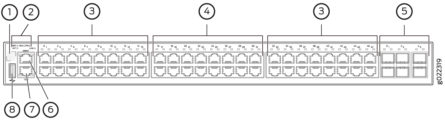
1 — QR code | 5 — 10-Gigabit Ethernet uplink ports |
2 — System LEDs | 6 — Management port |
3 — 10/100/1000 BASE-T Gigabit Ethernet ports with PoE/PoE+ capability | 7 — Console port |
4 — 100/1000/2500 BASE-T Gigabit Ethernet ports | 8 — USB port |
Environment
A transceiver is installed in the uplink port 4 or 5 or both.
Symptoms
When you check the status with the CLI command show interfaces ge or
with the J-Web user interface, the port is not listed.
Cause
EX2300-48MP switches do not support 10-Mbps and 100-Mbps speeds on uplink ports 4 and 5. This is an ASIC limitation.
Solution
Use the other ports if you need 10-Mbps and 100-Mbps speeds.