Hashing Algorithms for LAG and ECMP
Learn about hashing algorithms used for LAG and ECMP , and how to configure the hashing algorithms.
Understand the Algorithm Used to Hash LAG Bundle and Egress Next-Hop ECMP Traffic
Juniper Networks EX Series and QFX Series use a hashing algorithm to determine how to forward traffic over a link aggregation group (LAG) bundle or to the next-hop device when equal-cost multipath (ECMP) is enabled.
The hashing algorithm makes hashing decisions based on values in various packet fields, as well as on some internal values like source port ID and source device ID. You can configure some of the fields that are used by the hashing algorithm.
This topic contains the following sections:
- Understand the Hashing Algorithm
- IP (IPv4 and IPv6)
- MPLS
- MAC-in-MAC Packet Hashing
- Layer 2 Header Hashing
- Hashing Parameters
Understand the Hashing Algorithm
The hashing algorithm is used to make traffic-forwarding decisions for traffic entering a LAG bundle or for traffic exiting a switch when ECMP is enabled.
For LAG bundles, the hashing algorithm determines how traffic entering a LAG bundle is placed onto the bundle’s member links. The hashing algorithm tries to manage bandwidth by evenly load-balancing all incoming traffic across the member links in the bundle.
For ECMP, the hashing algorithm determines how incoming traffic is forwarded to the next-hop device.
The hashing algorithm makes hashing decisions based on values in various packet fields, as well as on some internal values like source port ID and source device ID. The packet fields used by the hashing algorithm varies by the packet’s EtherType and, in some instances, by the configuration on the switch. The hashing algorithm recognizes the following EtherTypes:
IP (IPv4 and IPv6)
MPLS
MAC-in-MAC
Traffic that is not recognized as belonging to any of these EtherTypes is hashed based on the Layer 2 header. IP and MPLS traffic are also hashed based on the Layer 2 header when a user configures the hash mode as Layer 2 header.
You can configure some fields that are used by the hashing algorithm to make traffic forwarding decisions. You cannot, however, configure how certain values within a header are used by the hashing algorithm.
Note the following points regarding the hashing algorithm:
The fields selected for hashing are based on the packet type only. The fields are not based on any other parameters, including forwarding decision (bridged or routed) or egress LAG bundle configuration (Layer 2 or Layer 3).
The same fields are used for hashing unicast and multicast packets. Unicast and multicast packets are, however, hashed differently.
The same fields are used by the hashing algorithm to hash ECMP and LAG traffic, but the hashing algorithm hashes ECMP and LAG traffic differently. LAG traffic uses a trunk hash while ECMP uses ECMP hashing. Both LAG and ECMP use the same RTAG7 seed but use different offsets of that 128B seed to avoid polarization. The initial config of the HASH function to use the trunk and ECMP offset are set at the PFE Init time. The different hashing ensures that traffic is not polarized when a LAG bundle is part of the ECMP next-hop path.
The same fields are used for hashing regardless of whether the switch is or is not participating in a mixed or non-mixed Virtual Chassis or Virtual Chassis Fabric (VCF).
The fields used for hashing by each EtherType as well as the fields used by the Layer 2 header are discussed in the following sections.
IP (IPv4 and IPv6)
Payload fields in IPv4 and IPv6 packets are used by the hashing algorithm when IPv4 or IPv6 packets need to be placed onto a member link in a LAG bundle or sent to the next-hop device when ECMP is enabled.
The hash mode is set to Layer 2 payload field, by default. IPv4 and IPv6 payload fields are used for hashing when the hash mode is set to Layer 2 payload.
If the hash mode is configured to Layer 2 header, IPv4, IPv6, and MPLS packets are hashed using the Layer 2 header fields. If you want incoming IPv4, IPv6, and MPLS packets hashed by the source MAC address, destination MAC address, or EtherType fields, you must set the hash mode to Layer 2 header.
Table 1 displays the IPv4 and IPv6 payload fields that are used by the hashing algorithm, by default.
✓—Field is used by the hashing algorithm, by default.
Χ—Field is not used by the hashing algorithm, by default.
(configurable)—Field can be configured to be used or not used by the hashing algorithm.
On EX2300 switches, following payload fields in IPv4 and IPv6 packets are used by the hashing algorithm when IPv4 or IPv6 packets need to be placed onto a member link in a LAG bundle or sent to the next-hop device when ECMP is enabled:
For unicast traffic on LAG - SIP, DIP, L4SP, L4DP
For known multicast traffic on LAG - Source IP, Destination IP, Ingress Mod Id, and Ingress Port Id
For broadcast, unknown unicast, and unknown multicast traffic on LAG - Source MAC, Destination MAC, Ingress Mod Id, and Ingress Port Id
ECMP load balancing: Destination IP, Layer 4 Source Port, and Layer 4 Destination Port
Fields |
EX3400 |
EX4300 |
QFX5100 |
QFX5110 and QFX5120 |
QFX5200 |
|||||
|---|---|---|---|---|---|---|---|---|---|---|
LAG |
ECMP |
LAG |
ECMP |
LAG |
ECMP |
LAG |
ECMP |
LAG |
ECMP |
|
Source MAC |
X |
Χ |
X |
Χ |
Χ |
Χ |
Χ |
Χ |
Χ |
X |
Destination MAC |
Χ |
Χ |
Χ |
Χ |
Χ |
Χ |
Χ |
Χ |
Χ |
Χ |
EtherType |
Χ |
Χ |
Χ |
Χ |
Χ |
Χ |
Χ |
Χ |
Χ |
Χ |
VLAN ID |
Χ (configurable) |
Χ (configurable) |
Χ (configurable) |
Χ (configurable) |
Χ (configurable) |
Χ (configurable) |
Χ (configurable) |
Χ (configurable) |
Χ (configurable) |
Χ (configurable) |
Source IP or IPv6 |
✓ (configurable) |
✓ (configurable) |
✓ (configurable) |
✓ (configurable) |
✓ (configurable) |
✓ (configurable) |
✓ (configurable) |
✓ (configurable) |
✓ (configurable) |
✓ (configurable) |
Destination IP or IPv6 |
✓ (configurable) |
✓ (configurable) |
✓ (configurable) |
✓ (configurable) |
✓ (configurable) |
✓ (configurable) |
✓ (configurable) |
✓ (configurable) |
✓ (configurable) |
✓ (configurable) |
Protocol (IPv4 only) |
✓ (configurable) |
✓ (configurable) |
✓ (configurable) |
✓ (configurable) |
✓ (configurable) |
✓ (configurable) |
✓ (configurable) |
✓ (configurable) |
✓ (configurable) |
✓ (configurable) |
Next header (IPv6 only) |
✓ (configurable) |
✓ (configurable) |
✓ (configurable) |
✓ (configurable) |
✓ (configurable) |
✓ (configurable) |
✓ (configurable) |
✓ (configurable) |
✓ (configurable) |
✓ (configurable) |
Layer 4 Source Port |
✓ (configurable) |
✓ (configurable) |
✓ (configurable) |
✓ (configurable) |
✓ (configurable) |
✓ (configurable) |
✓ (configurable) |
✓ (configurable) |
✓ (configurable) |
✓ (configurable) |
Layer 4 Destination Port |
✓ (configurable) |
✓ (configurable) |
✓ (configurable) |
✓ (configurable) |
✓ (configurable) |
✓ (configurable) |
✓ (configurable) |
✓ (configurable) |
✓ (configurable) |
✓ (configurable) |
IPv6 Flow label (IPv6 only) |
Χ |
Χ |
Χ |
Χ |
Χ |
Χ |
Χ |
Χ |
Χ |
Χ |
Ingress Mod Id |
✓ (configurable) |
Χ |
Χ |
Χ |
Χ |
Χ |
Χ |
Χ |
Χ |
Χ |
Ingress Port Id |
✓ (configurable) |
Χ |
Χ |
Χ |
Χ |
Χ |
Χ |
Χ |
Χ |
Χ |
MPLS
The hashing algorithm hashes MPLS packets using the source IP, destination IP, MPLS label 0, MPLS label 1, MPLS label 2, and MPLS 3 fields. ECMP uses these fields for hashing on an LSR router:
Layer 3 VPN: MPLS Labels (top 3 labels), source IP, destination IP, and ingress port ID
Layer 2 Circuit: MPLS Labels (top 3 labels) and ingress port ID
Use Feature Explorer to confirm platform and release support for specific features.
Table 2 displays the MPLS payload fields that are used by the hashing algorithm, by default:
✓—Field is used by the hashing algorithm, by default.
Χ—Field is not used by the hashing algorithm, by default.
The fields used by the hashing algorithm for MPLS packet hashing are not user-configurable.
The source IP and destination IP fields are not always used for hashing. For non-terminated MPLS packets, the payload is checked if the bottom of stack (BoS) flag is seen in the packet. If the payload is IPv4 or IPv6, then the IP source address and IP destination address fields are used for hashing along with the MPLS labels. If the BoS flag is not seen in the packet, only the MPLS labels are used for hashing.
Field |
EX3400 |
EX4300 |
QFX5100 |
QFX5110 and QFX5120 |
QFX5200 |
|
|---|---|---|---|---|---|---|
Source MAC |
Χ |
Χ |
Χ |
Χ |
Χ |
|
Destination MAC |
Χ |
Χ |
Χ |
Χ |
Χ |
|
EtherType |
Χ |
Χ |
Χ |
Χ |
Χ |
|
VLAN ID |
Χ |
Χ |
Χ |
Χ |
Χ |
|
Source IP |
✓ |
✓ |
✓ |
✓ |
✓ |
|
Destination IP |
✓ |
✓ |
✓ |
✓ |
✓ |
|
Protocol (for IPv4 packets) |
Χ |
Χ |
Χ |
Χ |
Χ |
|
Next header (for IPv6 packets) |
Χ |
Χ |
Χ |
Χ |
Χ |
|
Layer 4 Source Port |
Χ |
Χ |
Χ |
Χ |
Χ |
|
Layer 4 Destination Port |
Χ |
Χ |
Χ |
Χ |
Χ |
|
IPv6 Flow lab |
Χ |
Χ |
Χ |
Χ |
Χ |
|
MPLS label 0 |
Χ |
✓ |
✓ |
✓ |
✓ |
|
MPLS label 1 |
✓ |
✓ |
✓ |
✓ |
✓ |
|
MPLS label 2 |
✓ |
✓ |
✓ |
✓ |
✓ |
|
MPLS label 3 |
✓ |
X |
X |
X |
X |
|
Ingress Port ID |
✓ (LSR and L2Circuit) |
X |
X |
X |
✓ (LSR and L2Circuit) |
✓ (LSR and L2Circuit) |
MAC-in-MAC Packet Hashing
Packets using the MAC-in-MAC EtherType are hashed by the hashing algorithm using the Layer 2 payload source MAC, Layer 2 payload destination MAC, and Layer 2 payload EtherType fields. See Table 3.
Hashing using the fields in the MAC-in-MAC EtherType packet is first supported on EX4300 switches in Release 13.2X51-D20. Hashing using the fields in the MAC-in-MAC EtherType is not supported on earlier releases.
The fields used by the hashing algorithm for MAC-in-MAC hashing are not user-configurable.
✓—Field is used by the hashing algorithm, by default.
Χ—Field is not used by the hashing algorithm, by default.
Field |
EX3400 |
EX4300 |
QFX5100 |
QFX5110 and QFX5120 |
QFX5200 |
||
|---|---|---|---|---|---|---|---|
Layer 2 Payload Source MAC |
✓ |
✓ |
✓ |
✓ |
✓ |
||
Layer 2 Payload Destination MAC |
✓ |
✓ |
✓ |
✓ |
✓ |
||
Layer 2 Payload EtherType |
✓ |
✓ |
✓ |
✓ |
✓ |
||
Layer 2 Payload Outer VLAN |
✓ |
Χ |
Χ |
Χ |
Χ |
||
Layer 2 Header Hashing
Layer 2 header fields are used by the hashing algorithm when a packet’s EtherType is not recognized as IP (IPv4 or IPv6), MPLS, or MAC-in-MAC. The Layer 2 header fields are also used for hashing IPv4, IPv6, and MPLS traffic instead of the payload fields when the hash mode is set to Layer 2 header.
✓—Field is used by the hashing algorithm, by default.
Χ—Field is not used by the hashing algorithm, by default.
(configurable)—Field can be configured to be used or not used by the hashing algorithm.
Field |
EX3400 |
EX4300 |
QFX5100 |
QFX5110 and QFX5120 |
QFX5200 |
||
|---|---|---|---|---|---|---|---|
Source MAC |
✓ (configurable) |
✓ (configurable) |
✓ (configurable) |
✓ (configurable) |
✓ (configurable) |
||
Destination MAC |
✓ (configurable) |
✓ (configurable) |
✓ (configurable) |
✓ (configurable) |
✓ (configurable) |
||
EtherType |
✓ (configurable) |
✓ (configurable) |
✓ (configurable) |
✓ (configurable) |
✓ (configurable) |
||
VLAN ID |
Χ (configurable) |
Χ (configurable) |
Χ (configurable) |
✓ (configurable) |
✓ (configurable) |
||
Hashing Parameters
Starting in Junos OS Release 19.1R1, on the QFX5000 line of switches, you can change hashing parameters for the existing algorithms implemented. You can change the threshold of shared buffer pools for both ingress and egress buffer partitions and you can make changes to the hash function selection, hash algorithm, and other additional parameters. See Configuring Other Hashing Parameters later in this document.
Configure the Fields in the Algorithm Used to Hash LAG Bundle and ECMP Traffic
Juniper Networks EX Series and QFX Series switches use a hashing algorithm to determine how to forward traffic over a Link Aggregation group (LAG) bundle or to the next-hop device when equal-cost multipath (ECMP) is enabled.
Use Link aggregation group (LAG) bundle hashing configuration to confirm platform and release support for specific features.
The hashing algorithm makes hashing decisions based on values in various packet fields. You can configure some of the fields that are used by the hashing algorithm.
Configuring the fields used by the hashing algorithm is useful in scenarios where most of the traffic entering the bundle is similar and the traffic needs to be managed in the LAG bundle. For instance, if the only difference in the IP packets for all incoming traffic is the source and destination IP address, you can tune the hashing algorithm to make hashing decisions more efficiently by configuring the algorithm to make hashing decisions using only those fields.
- Configure the Hashing Algorithm to Use Fields in the Layer 2 Header for Hashing
- Configure the Hashing Algorithm to Use Fields in the IP Payload for Hashing
- Configure the Hashing Algorithm to Use Fields in the IPv6 Payload for Hashing
- Configure Other Hashing Parameters
Configure the Hashing Algorithm to Use Fields in the Layer 2 Header for Hashing
To configure the hashing algorithm to use fields in the Layer 2 header for hashing:
Configure the Hashing Algorithm to Use Fields in the IP Payload for Hashing
To configure the hashing algorithm to use fields in the IP payload for hashing:
Configure the Hashing Algorithm to Use Fields in the IPv6 Payload for Hashing
To configure the hashing algorithm to use fields in the IPv6 payload for hashing:
Configure Other Hashing Parameters
To configure hashing parameters for either ECMP or LAG traffic:
Example: Configure Link Aggregation Between a QFX Series Switches and an Aggregation Switch
A QFX Series product allows you to combine multiple Ethernet links into one logical interface for higher bandwidth and redundancy. The ports that are combined in this manner are referred to as a link aggregation group (LAG) or bundle. The number of Ethernet links you can combine into a LAG depends on your QFX Series product model. You can configure LAGs to connect a QFX Series product or an EX4600 switch to other switches, like aggregation switches, servers, or routers. This example describes how to configure LAGs to connect a QFX3500, QFX3600, EX4600, QFX5100, and QFX10002 switch to an aggregation switch.
Requirements
This example uses the following software and hardware components:
Junos OS Release 11.1 or later for the QFX3500 and QFX3600 switches, Junos OS 13.2 or later for the QFX5100 and EX4600 switch, and Junos OS Release 15.1X53-D10 or later for QFX10002 switches.
One QFX3500, QFX3600, EX4600, QFX5100, or QFX10002 switch.
Overview and Topology
In this example, the switch has one LAG comprising two 10-Gigabit Ethernet interfaces. This LAG is configured in port-mode trunk (or interface-mode trunk) so that the switch and the VLAN to which it has been assigned can send and receive traffic.
Configuring the Ethernet interfaces as LAGs has the following advantages:
If one physical port is lost for any reason (a cable is unplugged or a switch port fails), the logical port transparently continues to function over the remaining physical port.
Link Aggregation Control Protocol (LACP) can optionally be configured for link monitoring and automatic addition and deletion of individual links without user intervention.
If the remote end of the LAG link is a security device, LACP might not be supported because security devices require a deterministic configuration. In this case, do not configure LACP. All links in the LAG are permanently operational unless the switch detects a link failure within the Ethernet physical layer or data link layers.
The topology used in this example consists of one switch with a LAG configured between two of its 10-Gigabit Ethernet interfaces. The switch is connected to an aggregation switch.
Table 5 details the topology used in this configuration example.
| Hostname | Base Hardware | Trunk Port |
|---|---|---|
switch |
QFX3500, QFX3600, EX4600, QFX5100, or QFX10002 switch |
|
Configuration
To configure a LAG between two 10-Gigabit Ethernet interfaces.
Procedure
CLI Quick Configuration
To quickly configure a LAG between two 10-Gigabit Ethernet interfaces on a switch, copy the following commands and paste them into the switch terminal window:
To configure a LAG using Enhanced Layer 2 Software—for example, on the EX4600, QFX5100, or
QFX10002 switch—use the interface-mode statement
instead of the port-mode statement. For ELS details,
see Using the Enhanced Layer 2 Software
CLI.
[edit]
set chassis aggregated-devices ethernet device-count 1
set interfaces ae0 aggregated-ether-options minimum-links 1
set interfaces ae0 aggregated-ether-options link-speed 10g
set interfaces ae0 unit 0 family ethernet-switching vlan members green
set interfaces xe-0/0/2 ether-options 802.3ad ae0
set interfaces xe-0/0/3 ether-options 802.3ad ae0
set interfaces ae0 unit 0 family ethernet-switching port-mode trunk
set interfaces ae0 aggregated-ether-options lacp active
set interfaces ae0 aggregated-ether-options lacp periodic fast
Step-by-Step Procedure
To configure a LAG between a QFX Series switch and an aggregation switch:
Specify the number of LAGs to be created on the switch:
[edit chassis]
user@switch# set aggregated-devices ethernet device-count 1
Specify the number of links that need to be present for the
ae0LAG interface to beup:[edit interfaces] user@switch# set ae0 aggregated-ether-options minimum-links 1
Specify the media speed of the
ae0link:[edit interfaces] user@switch# set ae0 aggregated-ether-options link-speed 10g
Specify the members to be included within the aggregated Ethernet bundle:
[edit interfaces]
user@switch# set interfaces xe-0/0/2 ether-options 802.3ad ae0

[edit interfaces]
user@switch# set interfaces xe-0/0/3 ether-options 802.3ad ae0
Assign a port mode of trunk to the
ae0link:Note:To configure a LAG using ELS—for example, on the EX4600, QFX5100, or QFX10002 switch—use the
interface-modestatement instead of theport-modestatement. For ELS details, see Using the Enhanced Layer 2 Software CLI.[edit interfaces] user@switch# set ae0 unit 0 family ethernet-switching port-mode trunk
or
[edit interfaces]
user@switch# set ae0 unit 0 family ethernet-switching interface-mode trunk
Assign the LAG to a VLAN:
[edit interfaces]
user@switch# set ae0 unit 0 family ethernet-switching vlan members green vlan-id 200
(Optional): Designate one side of the LAG as active for LACP:
[edit interfaces]
user@switch# set ae0 aggregated-ether-options lacp active
(Optional): Designate the interval and speed at which the interfaces send LACP packets:
[edit interfaces]
user@switch# set ae0 aggregated-ether-options lacp periodic fast
Results
Display the results of the configuration on a QFX3500 or QFX3600 switch:
[edit]
chassis {
    aggregated-devices {
        ethernet {
            device-count 1;
        }
    }
}
green {
    vlan-id 200;
    }
}
interfaces {
    ae0 {
        aggregated-ether-options {
            link-speed 10g;
            minimum-links 1;
        }
        unit 0 {
            family ethernet-switching {
                port-mode trunk;
                    vlan {
                    members green;
                }
        }
    }
    xe-0/0/2 {
        ether-options {
            802.3ad ae0;
        }
    }
    xe-0/0/3 {
        ether-options {
            802.3ad ae0;
        }
    }
}
Verification
To verify that switching is operational and one LAG has been created, perform these tasks:
Verify That LAG ae0.0 Has Been Created
Purpose
Verify that LAG ae0.0
has been created on the switch.
Action
show interfaces ae0 terse
Interface               Admin Link Proto    Local                 Remote
ae0                     up    up
ae0.0                   up    up eth-switch
Meaning
The output confirms that the ae0.0
link is up and shows the family
and IP address assigned to this link.
Troubleshooting
Troubleshooting a LAG That Is Down
Problem
The show interfaces terse command shows
that the LAG is down.
Solution
Check the following:
Verify that there is no configuration mismatch.
Verify that all member ports are up.
Verify that a LAG is part of family ethernet switching (Layer 2 LAG) or family inet (Layer 3 LAG).
Verify that the LAG member is connected to the correct LAG at the other end.
Resilient Hashing on LAGs and ECMP groups
Resilient hashing helps minimize the flow remapping across equal cost multipath (ECMP) groups and LAGs in a load-balanced system. The topics below discuss the working, usage and configuring of resilient hashing on link aggregation groups (LAGs) and ECMP groups.
- Understand the Use of Resilient Hashing to Minimize Flow Remapping in LAGs/ECMP Groups
- Configure Resilient Hashing for LAGs/ECMP Groups
Understand the Use of Resilient Hashing to Minimize Flow Remapping in LAGs/ECMP Groups
You use resilient hashing to minimize flow remapping across members of a LAG/ECMP group in a load-balanced system. You can configure resilient hashing in LAG and in ECMP groups.
- Why You Might Want to Use Resilient Hashing and How It Works with Static Hashing
- Limitations and Caveats for Resilient Hashing
- Resilient Hashing on LAGs
- Resilient Hashing on ECMP
Why You Might Want to Use Resilient Hashing and How It Works with Static Hashing
Resilient hashing works with the default static hashing algorithm. When members are added to or deleted from a LAG/ECMP group, the static hashing algorithm might remap destination paths. With resilient hashing, the chances of a flow being remapped are minimal if its path is unaffected by the LAG/ECMP group's member change. When a flow is affected by a member change, the Packet Forwarding Engine rebalances the flow by reprogramming the FlowSet table.
Use Resilient Hashing for Load Balancing to confirm platform and release support for specific features.
Resilient hashing thus provides the following benefits:
Minimizes traffic-distribution imbalances among members of a LAG/ECMP group when members are added to or deleted from the group.
Minimizes the impact on flows bound to unaffected members when a new member is added or an existing member is deleted from the group.
In normal hash-based load balancing, with the static hashing algorithm used alone, flows are assigned to members through the mathematical mod (%) operation. Any increase or decrease in the number of group members results in a complete remapping of flows to member IDs, as shown in the following example:
Member ID = Hash (key) mod (number of members in group)
Example:
Hash (key) = 10
10 mod 5 = 0 (member with ID 0 is selected for flow)
10 mod 4 = 2 (member with ID 2 is selected for the same flow when the number of members is decreased by 1)
Resilient hashing minimizes the destination path remapping when a member in the LAG/ECMP group is added or deleted.
When the flow is affected by a member change in the group, resilient hashing rebalances the flow by reprogramming the FlowSet table.
LAG/ECMP Group Size |
Normal (Static) Hashing Result |
Resilient Hashing Result |
Notes |
|---|---|---|---|
4 |
Hash(10) % 4 = 2 Flow is assigned to member ID 2. |
Flow is assigned to one of four group members based on FlowSet table entries. |
Original LAG/ECMP group size is 4. |
3 |
Hash(10) % 3 = 1 Flow is assigned to member ID 1. |
Flow is assigned to same member as in the previous case. |
Delete one member from original LAG/ECMP group. LAG/ECMP group size is 3. |
5 |
Hash(10) % 5 = 0 Flow is assigned to member ID 0. |
There is minimal redistribution of flows from other members to this newly added member. |
Add one member to original LAG group. LAG/ECMP group size is 5. |
Limitations and Caveats for Resilient Hashing
Notice the following limitation and caveats for the resilient hashing feature:
-
Resilient hashing applies only to unicast traffic.
-
Resilient hashing supports a maximum of 1024 LAGs, with each group having a maximum of 256 members.
-
Resilient hashing does not guarantee that traffic distribution is even across all group members—it depends on the traffic pattern and on the organization of the resilient hashing FlowSet table in hardware. Resilient hashing minimizes remapping of flows to destination links when members are added to or deleted from the group.
-
If resilient hashing is enabled on a LAG or ECMP group and if
set
                            forwarding-options enhanced-hash-key
is used with one of the following options, some flows might change destination links. The reason is that the new hash parameters might generate new hash indexes for the flows.hash-modeinetinet6layer2
-
Resilient hashing is not supported on VCP links.
Resilient Hashing on LAGs
A LAG combines Ethernet interfaces (members) to form a logical point-to-point link that increases bandwidth, provides reliability, and allows load balancing. Resilient hashing minimizes destination remapping behavior when a new member is added or deleted from the LAG.
A resilient hashing configuration on LAGs is per-aggregated-Ethernet-interface–based.
Resilient Hashing on ECMP
An ECMP group for a route contains multiple next-hop equal cost addresses for the same destination in the routing table. Routes of equal cost have the same preference and metric values.
Junos OS uses the static hashing algorithm to choose one of the next-hop addresses in the ECMP group to install in the forwarding table. Resilient hashing enhances ECMPs by minimizing destination remapping behavior when a new member is added or deleted from the ECMP group.
A resilient hashing configuration on ECMP is global—it applies to all ECMP groups.
Configure Resilient Hashing for LAGs/ECMP Groups
You use resilient hashing to minimize flow remapping across members of a LAG/ECMP group in a load-balanced system. You can configure resilient hashing in LAGs and ECMP sets.
.
This topic includes:
Configure Resilient Hashing on LAGs
To enable resilient hashing for a LAG:
Configure Resilient Hashing on ECMP Groups
To enable resilient hashing for ECMP groups:
[edit forwarding-options]
user@switch# set enhanced-hash-key ecmp-resilient-hash
When resilient hashing is added or removed, the traffic distribution across all members of an ECMP group for a given flow are reprogrammed and, as a result, some flows might be remapped to new ECMP group members.
Use of Resilient Hashing to Minimize Flow Remapping
In deployments between network endpoints, it is necessary to preserve established connections and associated Layer 2 and Layer 3 paths. If there is any change in the network, such as failure of a networking device or a server, the packets take a new path.
Resilient hashing reduces the impact of the network change. Each ECMP with resilient hashing is assigned a 256-entry region in the load-balancing table (also known as macro-flow table). Each entry in the table stores member link ID assigned to that macro-flow.
Resilient hashing works as described below:
-
Hash incoming packets to one of these macro-flow entries or buckets.
-
You then link packets to the paths in the ECMP group.
If we use a "basket" to represent each member link/path, the resilient hashing operations can be modeled as putting buckets (macro flows) into one of the baskets.
If we have N buckets and P paths for ECMP group, use the following sequence:
-
The initial bucket mapping is generated using a round-robin method. Thus, all buckets are almost equally (N/P) distributed among the ECMP group members. Later, the buckets move around based on the path addition or deletion events.
If N=64 buckets and P=4 paths, you distribute all 64 buckets in a round-robin manner. Since you have 4 paths, there are 4 stacks. Each stack corresponds to one path. Each stack has the same number of buckets, N/P=16.
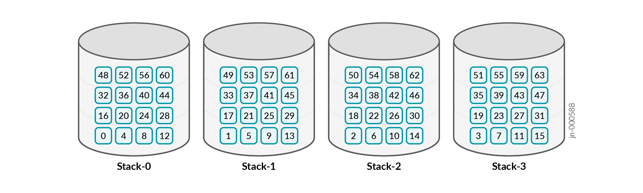
Last_processed_path= 0 (refer to Step 5 of the algorithm).
-
If there is a path failure or removal, you suddenly remove all the buckets from the failed path/stack and push them into remaining paths/stacks in a circular round-robin manner.
If you remove path 3 (Stack 3 in the above image), you need to move all the buckets from Stack 3 (orange in the figure below) to remaining stacks.
-
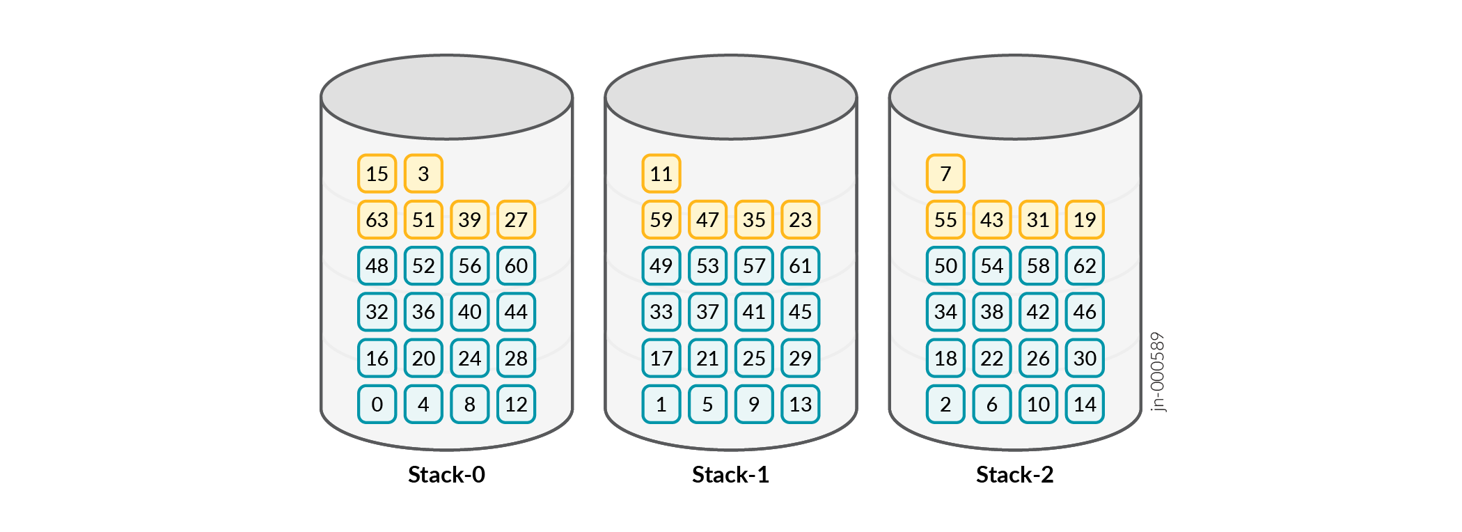
If there is a path addition, you suddenly remove N/(P+1) buckets from the existing paths in circular round-robin manner and push them into the newly added path/stack.
If you add a new path, you need to move N/P+1=64/4=16 buckets from existing stacks (stacks 0, 1, 2). All orange buckets are now back in stack 3, blue stacks are not moved and are intact.
Last_processed_path= 0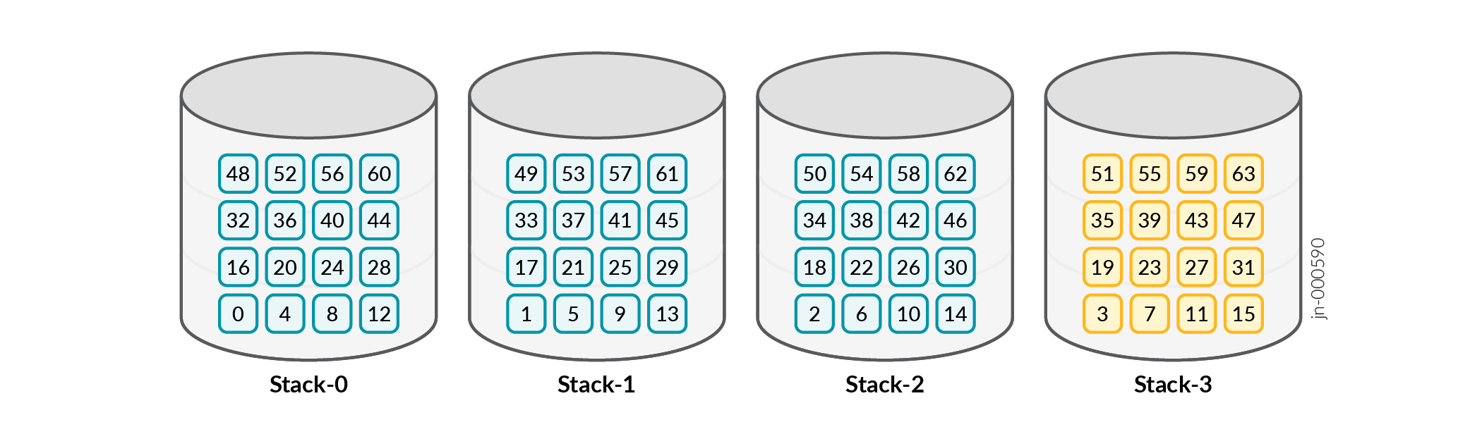
-
Circular round-robin direction for Step 2 and Step 3 is opposite. It is important to determine the first stack from which circular round-robin starts. You keep an index pointer
last_processed_paththat provides the start stack index for Step 2 and before start stack for Step 3. -
5. To set
last_processed_path, do the following:-
When you push buckets as in Step 2,
last_processed_pathis the next stack of the last stack where you pushed the last bucket. -
When you remove buckets as in Step 3,
last_processed_pathis the last stack from where the bucket was removed.
-
- Limitations and Caveats for Resilient Hashing
- Configuring Resilient Hashing for ECMP
- Configuring Resilient Hashing for Aggregated Ethernet Interfaces
Limitations and Caveats for Resilient Hashing
-
Resilient hashing is supported only on the equal-cost BGP routes based ECMP group. When you configure other protocols or static routes having higher priority than BGP routes, resilient hashing is not supported.
-
Resilient hashing is not supported on mixed speed LAG.
-
128-way ECMP resilient hashing is not supported with current design. Only 64-way ECMP resilient hashing is supported.
-
Mixed-Rate Aggregate Ethernet (AE) and Adaptive Load Balancing (ALB) AE are not supported with current resilient hashing design.
Configuring Resilient Hashing for ECMP
Configuring Resilient Hashing for Aggregated Ethernet Interfaces
user@router# set interface ae1 aggregated-ehter-options
                            resilient-hash
Change History Table
Feature support is determined by the platform and release you are using. Use Feature Explorer to determine if a feature is supported on your platform.