ON THIS PAGE
Traffic Load Balancer
Traffic Load Balancer Overview
- Traffic Load Balancing Support Summary
- Traffic Load Balancer Application Description
- Traffic Load Balancer Modes of Operation
- Traffic Load Balancer Functions
- Traffic Load Balancer Application Components
- Traffic Load Balancer Configuration Limits
Traffic Load Balancing Support Summary
Table 1 provides a summary of the traffic load balancing support on the MS-MPC and MS-MIC cards for Adaptive Services versus support on the MX-SPC3 security services card for Next Gen Services.
MS-MPC |
MX-SPC3 |
||
|---|---|---|---|
Junos Release |
< 16.1R6 & 18.2.R1 |
≥ 16.1R6 & 18.2R1 |
19.3R2 |
Max # of Instances per Chassis |
32 |
2,000 / 32 in L2 DSR mode |
2,000 |
Max # of Virtual Services per Instance |
32 |
32 |
32 |
Max # of virtual IP address per virtual service |
1 |
1 |
|
Max # of Groups per Instances |
32 |
32 |
32 |
Max # of Real-Services (Servers) per Group |
255 |
255 |
255 |
Max # of groups per virtual service |
1 |
1 |
|
Max # of Network Monitor Profiles per Group |
2 |
2 |
|
Max # of HC’s per security services per PIC/NPU in 5-sec’s |
4,000 |
1,250 – 19.3R2 10,000 – 20.1R1 |
|
Supported Health Check Protocols |
ICMP, TCP, UDP, HTTP, SSL, Custom |
ICMP, TCP, UDP, HTTP, SSL, TLS Hello, Custom |
|
Traffic Load Balancer Application Description
Traffic Load Balancer (TLB) is supported on MX Series routers with either of the Multiservices Modular Port Concentrator (MS-MPC), Multiservices Modular Interface Card (MS-MIC), or the MX Security Services Processing Card (MX-SPC3) and in conjunction with the Modular Port Concentrator (MPC) line cards supported on the MX Series routers as described in Table 2.
You cannot run Deterministic NAT and TLB simultaneously.
TLB Mode |
MX Platform Coverage |
|---|---|
Multiservices Modular Port Concentrator (MS-MPC) |
MX240, MX2480, MX960, MX2008, MX2010, MX2020 |
MX Security Services Processing Card (MX-SPC3) |
MX240, MX480, MX960 |
TLB enables you to distribute traffic among multiple servers.
TLB employs an MS-MPC-based control plane and a data plane using the MX Series router forwarding engine.
TLB uses an enhanced version of equal-cost multipath (ECMP). Enhanced ECMP facilitates the distribution of flows across groups of servers. Enhancements to native ECMP ensure that when servers fail, only flows associated with those servers are impacted, minimizing the overall network churn on services and sessions.
TLB provides application-based health monitoring for up to 255 servers per group, providing Intelligent traffic steering based on health checking of server availability information. You can configure an aggregated multiservices (AMS) interface to provide one-to-one redundancy for MS-MPCs or Next Gen Services MX-SPC3 card used for server health monitoring.
TLB applies its flow distribution processing to ingress traffic.
TLB supports multiple virtual routing instances to provide improved support for large scale load balancing requirements.
TLB supports static virtual-IP-address-to-real-IP-address translation, and static destination port translation during load balancing.
Traffic Load Balancer Modes of Operation
Traffic Load Balancer provides three modes of operation for the distribution of outgoing traffic and for handling the processing of return traffic.
Table 3 summarizes the TLB support and which cards it’s supported on.
Security Service Card |
MS-MPC |
MX-SPC3 |
|---|---|---|
Translate |
Yes |
Yes |
Transparent Layer 3 Direct Server Return |
Yes |
Yes |
Transparent Layer 2 Direct Server Return |
Yes |
Not Supported |
- Transparent Mode Layer 2 Direct Server Return
- Translated Mode
- Transparent Mode Layer 3 Direct Server Return
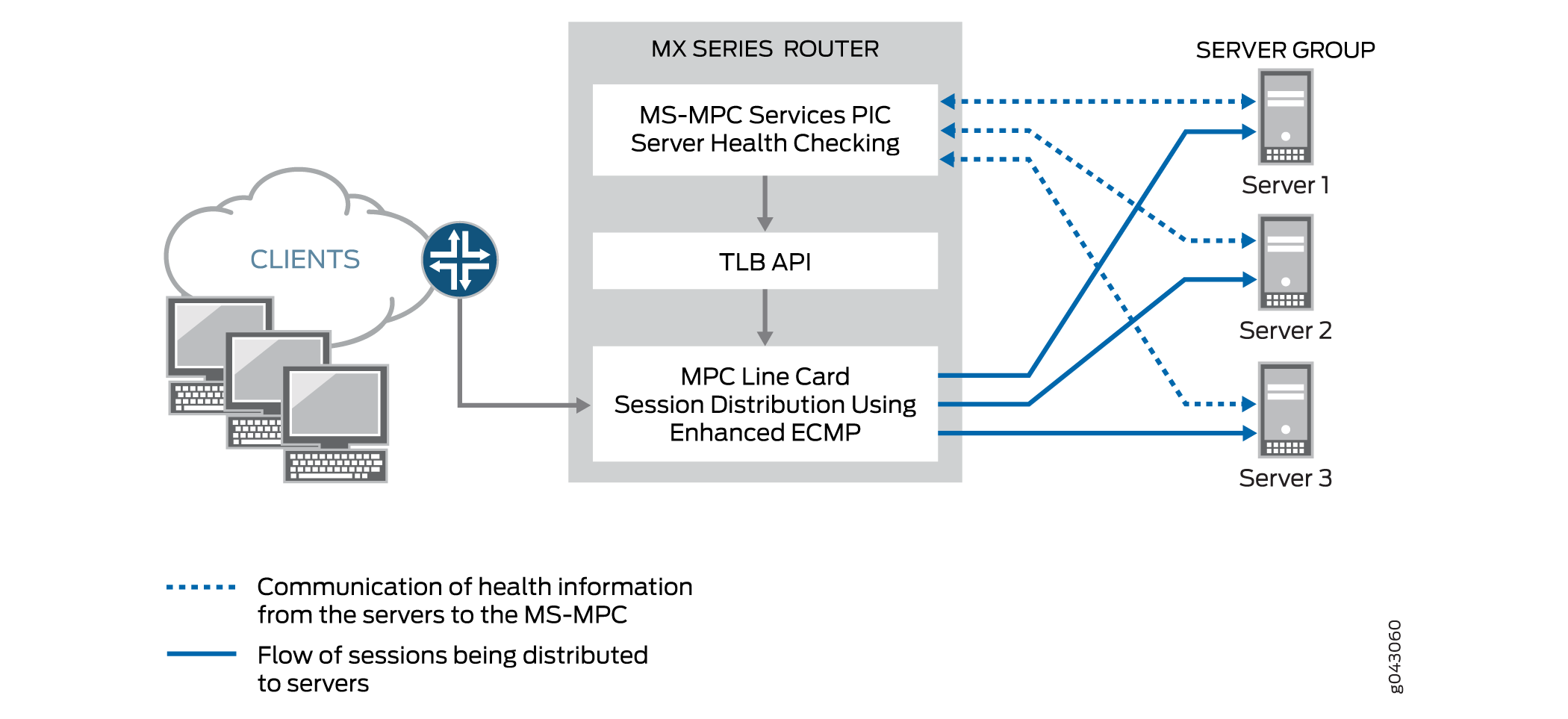
Transparent Mode Layer 2 Direct Server Return
When you use transparent mode Layer 2 direct server return (DSR):
The PFE processes data.
Load balancing works by changing the Layer 2 MAC of packets.
An MS-MPC performs the network-monitoring probes.
Real servers must be directly (Layer 2) reachable from the MX Series router.
TLB installs a route and all the traffic over that route is load-balanced.
TLB never modifies Layer 3 and higher level headers.
Figure 1 shows the TLB topology for transparent mode Layer 2 DSR.
Translated Mode
Translated mode provides greater flexibility than transparent mode Layer 2 DSR. When you choose translated mode:
An MS-MPC performs the network-monitoring probes.
The PFE performs stateless load balancing:
Data traffic directed to a virtual IP address undergoes translation of the virtual IP address to a real server IP address and translates the virtual port to a server listening port. Return traffic undergoes the reverse translation.
Client to virtual IP traffic is translated; the traffic is routed to reach its destination.
Server-to-client traffic is captured using implicit filters and directed to an appropriate load-balancing next hop for reverse processing. After translation, traffic is routed back to the client.
Two load balancing methods are available: random and hash. The random method is only for UDP traffic and provides quavms-random distribution. While not literally random, this mode provides fair distribution of traffic to an available set of servers. The hash method provides a hash key based on any combination of the source IP address, destination IP address, and protocol.
Note:Translated mode processing is only available for IPv4-to-IPv4 and IPv6-to-IPv6 traffic.
Figure 2 shows the TLB topology for translated mode.
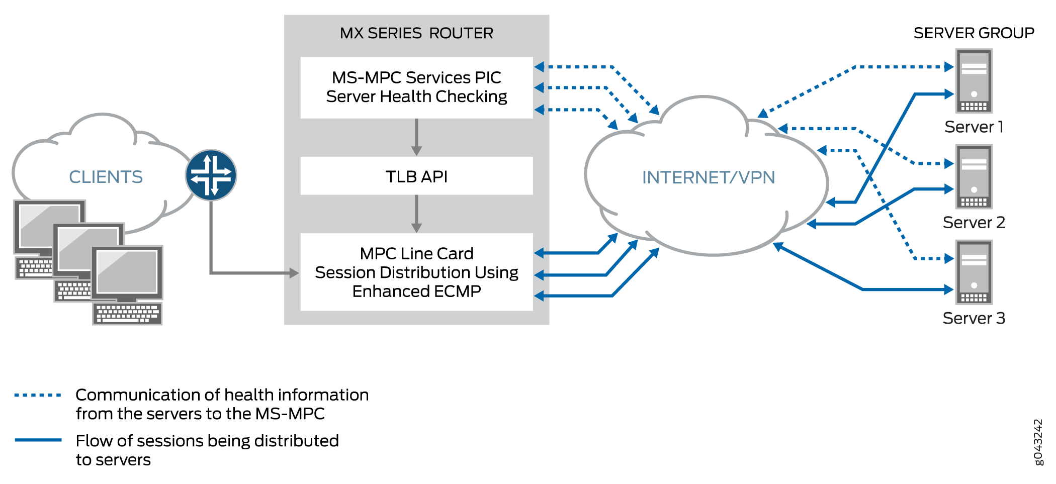
Transparent Mode Layer 3 Direct Server Return
Transparent mode Layer 3 DSR load balancing distributes sessions to servers that can be a Layer 3 hop away. Traffic is returned directly to the client from the real-server.
Traffic Load Balancer Functions
TLB provides the following functions:
TLB always distributes the requests for any flow. When you specify DSR mode, the response returns directly to the source. When you specify translated mode, reverse traffic is steered through implicit filters on server-facing interfaces.
TLB supports hash-based load balancing or random load balancing.
TLB enables you to configure servers offline to prevent a performance impact that might be caused by a rehashing for all existing flows. You can add a server in the administrative down state and use it later for traffic distribution by disabling the administrative down state. Configuring servers offline helps prevent traffic impact to other servers.
When health checking determines a server to be down, only the affected flows are rehashed.
When a previously down server is returned to service, all flows belonging to that server based on hashing return to it, impacting performance for the returned flows. For this reason, you can disable the automatic rejoining of a server to an active group. You can return servers to service by issuing the
request services
traffic-load-balance real-service rejoin
operational command.Note:NAT is not applied to the distributed flows.
Health check monitoring application runs on an MS-MPC/NPU. This network processor unit (NPU) is not used for handling data traffic.
TLB supports static virtual-IP-adddress-to-real-IP-address translation, and static destination port translation during load balancing.
TLB provides multiple VRF support.
Traffic Load Balancer Application Components
- Servers and Server Groups
- Server Health Monitoring — Single Health Check and Dual Health Check
- Virtual Services
Servers and Server Groups
TLB enables configuration of groups of up to 255 servers (referred to in configuration statements as real services) for use as alternate destinations for stateless session distribution. All servers used in server groups must be individually configured before assignment to groups. Load balancing uses hashing or randomization for session distribution. Users can add and delete servers to and from the TLB server distribution table and can also change the administrative status of a server.
TLB uses the session distribution next-hop API to update the server distribution table and retrieve statistics. Applications do not have direct control on the server distribution table management. They can only influence changes indirectly through the add and delete services of the TLB API.
Server Health Monitoring — Single Health Check and Dual Health Check
TLB supports TCP, HTTP, SSL Hello, TLS Hello, and custom health check probes to monitor the health of servers in a group. You can use a single probe type for a server group, or a dual health check configuration that includes two probe types. The configurable health monitoring function resides on either an MX-SPC3 or an MS-MPC. By default, probe requests are sent every 5 seconds. Also by default, a real server is declared down only after five consecutive probe failures and declared up only after five consecutive probe successes.
Use a custom health check probe to specify the following:
-
Expected string in the probe response
-
String that is sent with the probe
-
Server status to assign when the probe times out (up or down)
-
Server status to assign when the expected response to the probe is received (up or down)
-
Protocol — UDP or TCP
TLB provides application stickiness, meaning that server failures or changes do not affect traffic flows to other active servers. Changing a server’s administrative state from up to down does not impact any active flows to remaining servers in the server distribution table. Adding a server or deleting a server from a group has some traffic impact for a length of time that depends on your configuration of the interval and retry parameters in the monitoring profile.
TLB provides two levels of server health monitoring:
-
Single Health Check—One probe type is attached to a server group by means of the
network-monitoring-profileconfiguration statement. -
TLB Dual Health Check (TLB-DHC)—Two probe types are associated with a server group by means of the
network-monitoring-profileconfiguration statement. A server’s status is declared based on the result of two health check probes. Users can configure up to two health check profiles per server group. If a server group is configured for dual health check, a real-service is declared to be UP only when both health-check probes are simultaneously UP; otherwise, a real-service is declared to be DOWN.
The following restrictions apply to AMS interfaces used for server health monitoring:
-
An AMS interface configured under a TLB instance uses its configured member interfaces exclusively for health checking of configured multiple real servers.
-
The member interfaces use unit 0 for single VRF cases, but can use units other than 1 for multiple VRF cases.
-
TLB uses the IP address that is configured for AMS member interfaces as the source IP address for health checks.
-
The member interfaces must be in the same routing instance as the interface used to reach real servers. This is mandatory for TLB server health-check procedures.
Starting in Junos OS Release 24.2R1, when TLS and SSL are configured in the same group, the OR mechanism is used now instead of AND to determine the status of the real server. That is, the real server is marked as UP if any one of the probes is working. Previously, the real server was marked UP only if both the probes succeeded.
When the SSL probing version is provided, it probes with that version. When the SSL version is not specified, the behavior changes to Fallback from version v3 to v2. The probe starts with SSLv3. If the SSLv3 probe fails, the system probes for SSLv2. Previously, when the version attribute was not provided explicitly, the probing was done with the default version, v3.
This health check behavior enhancement is applicable only when the TLS and SSL probes are configured in the same health check group.
The output for show services traffic-load-balance statistics instance <inst> extensive is changed.
user@host# show services
                traffic-load-balance statistics instance
<inst-name>Traffic load balance instance name : <inst-name> Multi services interface name : vms-3/0/0 Interface state : UP Interface type : Multi services Route hold timer : 180 Active real service count : 0 Total real service count : 8 Traffic load balance virtual svc name : vs1 IP address : 60.0.0.1 Virtual service mode : Translate mode Routing instance name : fwd_instance_1 Traffic load balance group name : group1 Traffic load balance group warmup time: 15 Traffic load balance group auto-rejoin: TRUE Health check interface subunit : 0 Traffic load balance group down count : 5 Protocol : tcp Port number : 443 Server Listening Port Number : 443 Route metric : 1 Virtual service down count : 5 Traffic load balance hash method : source Network monitoring profile count : 2 Active real service count : 0 Total real service count : 8 Demux Nexthop index : 673 Nexthop index : 674 Down time : 6d 00:01 Total packet sent count : 361749 Total byte sent count : 55165331 Total packet received count : 542636 Total byte received count : 28940680 Network monitoring profile index : 1 Network monitoring profile name : nm_prof_ssl Probe type : SSL-HELLO Probe interval : 2 Probe failure retry count : 5 Probe recovery retry count : 3 Port number : 443 Network monitoring profile index : 2 Network monitoring profile name : nm_prof_tls Probe type : TLS-HELLO Probe interval : 5 Probe failure retry count : 5 Probe recovery retry count : 5 Port number : 443 Traffic load balance real svc name : rs_1 Routing instance name : server_vrf_1 IP address : 40.1.1.2 Traffic load balance group name : group1 Admin state : UP Oper state : UP Network monitoring probe up count : 1 Network monitoring probe down count : 1 Total rejoin event count : 8 Total up event count : 9 Total down event count : 9 Real Service packet sent count : 69804 Real Service byte sent count : 10644724 Real Service packet received count : 104706 Real Service byte received count : 5584336 Total probe sent : 358307 Total probe success : 76 Total probe fail : 358231 Total probe sent failed : 0 Network monitoring profile index : 1 Network monitoring profile name : nm_prof_sslv3 Probe type : SSL-HELLO Probe state : UP SSL probe version : 3 Probe sent : 255933 Probe success : 255879 Probe fail : 54 Probe sent failed : 0 Probe consecutive success : 254635 Probe consecutive fail : 0 Network monitoring profile index : 2 Network monitoring profile name : nm_prof_tls Probe type : TLS-HELLO Probe state : DOWN TLS probe version : 1.2 Probe sent : 102374 Probe success : 22 Probe fail : 102352 Probe sent failed : 0 Probe consecutive success : 0 Probe consecutive fail : 101854
The SSL-hello probe version is moved under real server statistics from virtual service when SSL version is not specified under health check profile.
Virtual Services
The virtual service provides a virtual IP address (VIP) that is associated with the group of servers to which traffic is directed as determined by hash-based or random session distribution and server health monitoring. In the case of L2 DSR and L3 DSR, the special address 0.0.0.0 causes all traffic flowing to the forwarding instance to be load balanced.
The virtual service configuration includes:
-
Mode—indicating how traffic is handled (translated or transparent).
-
The group of servers to which sessions are distributed.
-
The load balancing method.
-
Routing instance and route metric.
Although you can assign a virtual address of 0.0.0.0 in order to use default routing, we recommend using a virtual address that can be assigned to a routing instance set up specifically for TLB.
Traffic Load Balancer Configuration Limits
Traffic Load Balancer configuration limits are described in Table 4.
Configuration Component |
Configuration Limit |
|---|---|
Maximum number of instances |
Starting in Junos OS Release 16.1R6 and Junos OS Release 18.2R1, the TLB application supports 2000 TLB instances for virtual services that use the direct-server-return or the translated mode. In earlier releases, the maximum number of instances is 32. If multiple virtual services are using the same server group, then all of those virtual services must use the same load balancing method to support 2000 TLB instances. For virtual services that use the layer2-direct-server-return mode, TLB supports only 32 TLB instances. To perform the same function as the layer2-direct-server-return mode and have support for 2000 TLB instances, you can use the direct-server-return mode and use a service filter with the skip action. |
Maximum number of servers per group |
255 |
Maximum number of virtual services per services PIC |
32 |
Maximum number of health checks per services PIC in a 5-second interval |
For MS-MPC services cards: 2000 For Next Gen Services mode and the MX-SPC3 services cards: 1250 |
Maximum number of groups per virtual service |
1 |
Maximum number of virtual IP addresses per virtual service |
1 |
Supported health checking protocols |
ICMP, TCP, HTTP, SSL, TLS-Hello, Custom Note:
ICMP health checking is supported only on MS-MPC services cards. Starting in Junos OS release 22.4R1, TLB is enhanced to support TLS-Hello health check type. For TLS-Hello over TCP, TLS v1.2 and v1.3 health checks are supported. |
See Also
Configuring TLB
The following topics describe how to configure TLB. To create a complete application, you must also define interfaces and routing information. You can optionally define firewall filters and policy options in order to differentiate TLB traffic.
- Loading the TLB Service Package
- Configuring a TLB Instance Name
- Configuring Interface and Routing Information
- Configuring Servers
- Configuring Network Monitoring Profiles
- Configuring Server Groups
- Configuring Virtual Services
- Configuring Tracing for the Health Check Monitoring Function
Loading the TLB Service Package
Load the TLB service package on each service PIC on which you want to run TLB.
For Next Gen Services and the MX-SPC3 services card, you do not need to load this package.
To load the TLB service package on a service PIC:
Load the
jservices-traffic-dirdpackage.[edit chassis fpc slot-number pic pic-number adaptive-services service-package extension-provider] user@host# set package jservices-traffic-dird
For example:
[edit chassis fpc 3 pic 0 adaptive-services service-package extension-provider]
user@host# set package jservices-traffic-dird
Configuring a TLB Instance Name
system processes sdk-service enable at the [edit]
hierarchy.To configure a name for the TLB instance:
-
At the
[edit services traffic-load-balance]hierarchy level, identify the TLB instance name.[edit services traffic-load-balance] user@host# set instance instance-name
For example:
[edit services traffic-load-balance]
user@host# set instance tlb-instance1
Configuring Interface and Routing Information
To configure interface and routing information:
Configuring Servers
To configure servers for the TLB instance:
[edit services traffic-load-balance instance instance-name] user@host# set real-service real-service-name address server-ip-address
For example:
[edit services traffic-load-balance instance tlb-instance1]
user@host# set real-service rs138 address 172.26.99.138
user@host# set real-service rs139 address 172.26.99.139
user@host# set real-service rs140 address 172.26.99.140
Configuring Network Monitoring Profiles
A network monitoring profile configures a health check probe, which you assign to a server group to which session traffic is distributed.
To configure a network monitoring profile:
Configuring Server Groups
Server groups consist of servers to which traffic is distributed by means of stateless, hash-based session distribution and server health monitoring.
To configure a server group:
Configuring Virtual Services
A virtual service provides an address that is associated with a the group of servers to which traffic is directed as determined by hash-based or random session distribution and server health monitoring. You may optionally specify filters and routing instances to steer traffic for TLB.
To configure a virtual service:
Configuring Tracing for the Health Check Monitoring Function
To configure tracing options for the health check monitoring function:
Change History Table
Feature support is determined by the platform and release you are using. Use Feature Explorer to determine if a feature is supported on your platform.