Static Source NAT
Configuring Static Source Translation in IPv4 Networks
To configure the translation type as basic-nat44, you must configure the NAT pool and rule, service set with service interface, and trace options. This topic includes the following tasks:
- Configuring the NAT Pool and Rule
- Configuring the Service Set for NAT
- Configuring Trace Options
- Sample Configuration - Static Source NAT Using a Static Pool With An Address Prefix And An Address Range
- Sample Configuration - Static Source Nat for One-To-One Mapping Between a Private Subnet and a Public Subnet
Configuring the NAT Pool and Rule
To configure the NAT pool, rule, and term:
If you don’t configure a stateful firewall (SFW) rule for your traffic, then each packet is subjected to the following default stateful firewall rule:
Allow any valid packets from inside to outside.
Create forward and return flow based on packets 5-tuple.
Allow only valid packets matching return flows from outside to inside.
The stateful firewall’s packet validity checks are described in the Stateful Firewall Anomaly Checking in Junos Network Secure Overview. When a packets pass stateful firewall validity checking but are not matched by a NAT rule, they are not translated and may be forwarded if the NAT node has a valid route to the packets’ destination IP addresses.
When you add or delete a parameter in the from statement (NAT rule term match condition) at the [edit services
service-set service-set-name nat-rules rule-name term term- name] hierarchy level, this
configuration change triggers a deletion and addition of the NAT policy
(which is equivalent to the deactivation and activation of a service
set) that causes all existing NAT mappings to be deleted. Because
the sessions are not closed owing to the change in the NAT policy,
this behavior causes the mappings to timeout immediately after the
sessions are closed. This behavior is expected and is applicable only
with Junos OS Extension-Provider packages installed on a device. When
a NAT policy is deleted and readded, only EIM mappings are deleted.
This NAT policy change does not deactivate and activate the service
set. We recommend that you deactivate
and reactivate the service set in such scenarios in Junos OS Release
14.2 and earlier.
Configuring the Service Set for NAT
To configure the service set for NAT:
Configuring Trace Options
To configure the trace options:
[edit]
user@host# show services
service-set s1 {
    nat-rules rule-basic-nat44;
    interface-service {
        service-interface ms-1/2/0;
    }
}
nat {
    pool src_pool {
        address 10.10.10.2/32;
    }
    rule rule-basic-nat44 {
        match-direction input;
        term t1 {
            from {
                source-address {
                    3.1.1.2/32;
                }
            }
            then {
                translated {
                    source-pool src_pool;
                    translation-type {
                        basic-nat44;
                    }
                }
            }
        }
    }
}
adaptive-services-pics {
    traceoptions {
        flag all;
    }
}
Sample Configuration - Static Source NAT Using a Static Pool With An Address Prefix And An Address Range
[edit services nat]
pool p1 {
    address 30.30.30.252/30;
    address-range low 20.20.20.1 high 20.20.20.2;
}
rule r1 {
    match-direction input;
    term t1 {
        from {
            source-address {
                10.10.10.252/30;
            }
        }
        then {
            translated {
                source-pool p1;
                translation-type basic-nat44;
            }
        }
    }
}
Sample Configuration - Static Source Nat for One-To-One Mapping Between a Private Subnet and a Public Subnet
[edit]
user@host# show services
service-set s1 {
    nat-rules rule-basic-nat44;
    interface-service {
        service-interface ms-1/2/0;
    }
}
nat {
    pool src_pool {
        address 10.10.10.2/32;
    }
    rule rule-basic-nat44 {
        match-direction input;
        term t1 {
            from {
                source-address {
                    3.1.1.2/32;
                }
            }
            then {
                translated {
                    source-pool src_pool;
                    translation-type {
                        basic-nat44;
                    }
                }
            }
        }
    }
}
adaptive-services-pics {
    traceoptions {
        flag all;
    }
}[edit interfaces]
user@host# show
xe-1/1/0 {
unit 0 {
family inet {
service {
input {
service-set s1;
}
output {
service-set s1;
}
}
address 10.255.247.2/24;
}
}
}Configuring Static Source Translation in IPv6 Networks
To configure the translation type as basic-nat66, you must configure the NAT pool and rule, service set with service
interface, and trace options. The basic-nat66 translation
type is not available if you are using MS-MPCs or MS-MICs.
This topic includes the following tasks:
Configuring the NAT Pool and Rule
To configure the NAT pool, rule, and term:
Configuring the Service Set for NAT
To configure the service set for NAT:
Configuring Trace Options
To configure the trace options at the [edit services
adaptive-services-pics] hierarchy level:
The following example configures the translation type as basic-nat66.
[edit]
user@host# show services
service-set s1 {
    nat-rules rule-basic-nat66;
    interface-service {
        service-interface sp-1/2/0;
    }
}
nat {
    pool src_pool {
        address 10.10.10.2/32;
    }
    rule rule-basic-nat66 {
        match-direction input;
        term t1 {
            from {
                source-address {
                    2001:db8:10::0/96/96;
                }
            }
            then {
                translated {
                    source-pool src_pool;
                    translation-type {
                        basic-nat66;
                    }
                }
            }
        }
    }
}
adaptive-services-pics {
    traceoptions {
        flag all;
    }
}
Example: Configuring Basic NAT44
This example describes how to implement a basic NAT44 configuration.
Requirements
This example uses the following hardware and software components:
An MX Series 5G Universal Routing Platform with a Services DPC or an M Series Multiservice Edge router with a services PIC
A domain name server (DNS)
Junos OS Release 11.4 or higher
Overview
This example shows a complete CGN NAT44 configuration and advanced options.
Configuring Basic NAT44
Chassis Configuration
Step-by-Step Procedure
To configure the service PIC (FPC 5 Slot 0) with the Layer 3 service package:
Go to the [edit chassis] hierarchy level.
user@host# edit chassisConfigure the Layer 3 service package.
[edit chassis]user@host# set fpc 5 pic 0 adaptive-services service-package layer-3
Interfaces Configuration
Step-by-Step Procedure
To configure interfaces to the private network and the public Internet:
Define the interface to the private network.
user@host# edit interfaces ge-1/3/5
[edit interfaces ge-1/3/5]user@host# set description “Private” user@host# edit unit 0 family inet[edit interfaces ge-1/3/5 unit 0 family inet]user@host# set service input service-set ss2 user@host# set service output service-set ss2 user@host# set address 9.0.0.1/24Define the interface to the public Internet.
user@host# edit interfaces ge-1/3/6
[edit interfaces ge-1/3/6]user@host# set description “Public” user@host# set unit 0 family inet address 128.0.0.1/24Define the service interface for NAT processing.
user@host# edit interfaces sp-5/0/0
[edit interfaces sp-5/0/0]user@host# set unit 0 family inet
Results
user@host# show interfaces ge-1/3/5
description Private;
unit 0 {
    family inet {
        service {
            input {
                 service-set sset2;
            }
            output {
                service-set sset2;
            }
        }
        address 9.0.0.1/24;
    }
}
}user@host# show interfaces ge-1/3/6
description Public:;
unit 0 {
family inet {
address 128.0.0.1/24;
}
}user@host# show interfaces sp-5/0/0
unit 0 {
family inet;
}Example: Configuring NAT for Multicast Traffic
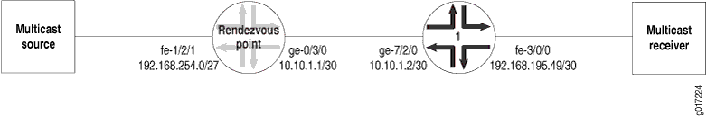
Figure 1 illustrates the network setup for the following configuration, which allows IP multicast traffic to be sent to the Multiservices PIC.
Rendezvous Point Configuration
On the rendezvous point (RP), all incoming traffic from the multicast source at 192.168.254.0/27 is sent to the static NAT pool mcast_pool, where its source is translated to 20.20.20.0/27. The service set nat_ss is a next-hop service set that allows IP multicast traffic to be sent to the Multiservices DPC or Multiservices PIC. The inside interface on the PIC is ms-1/1/0.1 and the outside interface is ms-1/1/0.2.
[edit services]
nat {
    pool mcast_pool {
        address 20.20.20.0/27;
    }
    rule nat_rule_1 {
        match-direction input;
        term 1 {
            from {
                source-address 192.168.254.0/27;
            }
        }
        then {
            translated {
                source-pool mcast_pool;
                translation-type basic-nat44;
            }
            syslog;
        }
    }
}
service-set nat_ss {
    allow-multicast;
    nat-rules nat_rule_1;
    next-hop-service {
        inside-service-interface ms-1/1/0.1;
        outside-service-interface ms-1/1/0.2;
    }
}
The Gigabit Ethernet interface ge-0/3/0 carries traffic out of the RP to Router 1. The multiservices interface ms-1/1/0 has two logical interfaces: unit 1 is the inside interface for next-hop services and unit 2 is the outside interface for next-hop services. Multicast source traffic comes in on the Fast Ethernet interface fe-1/2/1, which has the firewall filter fbf applied to incoming traffic.
[edit interfaces]
ge-0/3/0 {
    unit 0 {
        family inet {
            address 10.10.1.1/30;
        }
    }
}
ms-1/1/0 {
    unit 0 {
        family inet;
    }
    unit 1 {
        family inet;
        service-domain inside;
    }
    unit 2 {
        family inet;
        service-domain outside;
    }
}
fe-1/2/1 {
    unit 0 {
        family inet {
            filter {
                input fbf;
            }
            address 192.168.254.27/27;
        }
    }
}
Multicast packets can only be directed to the Multiservices DPC or the Multiservices PIC using a next-hop service set. In the case of NAT, you must also configure a VPN routing and forwarding instance (VRF). Therefore, the routing instance stage is created as a “dummy” forwarding instance. To direct incoming packets to stage, you configure filter-based forwarding through a firewall filter called fbf, which is applied to the incoming interface fe-1/2/1. A lookup is performed in stage.inet.0, which has a multicast static route that is installed with the next hop pointing to the PIC’s inside interface. All multicast traffic matching this route is sent to the PIC.
[edit firewall]
filter fbf {
    term 1 {
        then {
            routing-instance stage;
        }
    }
}
The routing instance stage forwards IP multicast traffic to the inside interface ms-1/1/0.1 on the Multiservices DPC or Multiservices PIC:
[edit]
routing-instances stage {
    instance-type forwarding;
    routing-options {
        static {
            route 224.0.0.0/4 next-hop ms-1/1/0.1;
        }
    }
}
You enable OSPF and Protocol Independent Multicast (PIM) on the Fast Ethernet and Gigabit Ethernet logical interfaces over which IP multicast traffic enters and leaves the RP. You also enable PIM on the outside interface (ms-1/1/0.2) of the next-hop service set.
[edit protocols]
ospf {
    area 0.0.0.0 {
        interface fe-1/2/1.0 {
            passive;
        }
        interface lo0.0;
        interface ge-0/3/0.0;
    }
}
pim {
    rp {
        local {
            address 10.255.14.160;
        }
    }
    interface fe-1/2/1.0;
    interface lo0.0;
    interface ge-0/3/0.0;
    interface ms-1/1/0.2;
}
As with any filter-based forwarding configuration, in order for the static route in the forwarding instance stage to have a reachable next hop, you must configure routing table groups so that all interface routes are copied from inet.0 to the routing table in the forwarding instance. You configure routing tables inet.0 and stage.inet.0 as members of fbf_rib_group, so that all interface routes are imported into both tables.
[edit routing-options]
interface-routes {
    rib-group inet fbf_rib_group;
}
rib-groups fbf_rib_group {
    import-rib [ inet.0 stage.inet.0 ];
}
multicast {
    rpf-check-policy no_rpf;
}
Reverse path forwarding (RPF) checking must be disabled for the multicast group on which source NAT is applied. You can disable RPF checking for specific multicast groups by configuring a policy similar to the one in the example that follows. In this case, the no_rpf policy disables RPF check for multicast groups belonging to 224.0.0.0/4.
[edit policy-options]
policy-statement no_rpf {
    term 1 {
        from {
            route-filter 224.0.0.0/4 orlonger;
        }
        then reject;
    }
}
Router 1 Configuration
The Internet Group Management Protocol (IGMP), OSPF, and PIM configuration on Router 1 is as follows. Because of IGMP static group configuration, traffic is forwarded out fe-3/0/0.0 to the multicast receiver without receiving membership reports from host members.
[edit protocols]
igmp {
    interface fe-3/0/0.0 {
    }
}
ospf {
    area 0.0.0.0 {
        interface fe-3/0/0.0 {
            passive;
        }
        interface lo0.0;
        interface ge-7/2/0.0;
    }
    pim {
        rp {
            static {
                address 10.255.14.160;
            }
        }
        interface fe-3/0/0.0;
        interface lo0.0;
        interface ge-7/2/0.0;
    }
}
The routing option creates a static route to the NAT pool, mcast_pool, on the RP.
[edit routing-options]
static {
    route 20.20.20.0/27 next-hop 10.10.1.1;
}
Change History Table
Feature support is determined by the platform and release you are using. Use Feature Explorer to determine if a feature is supported on your platform.