Packet Translation and GRE Tunneling
Packet Translation and GRE Tunneling-Overview
MX routers, when deployed as Enterprise edge routers, form part of the public cloud computing platform. The enterprise edge router tunnels the IPv4 traffic received from customer VPN to the route gateway nodes. The route gateway performs IPv4-to-IPv6 translation and sends the translated packets to the Platform-as-a-service (PaaS) servers. PaaS is a complete development and deployment environment in the cloud, with resources that enable enterprises to deliver applications ranging from simple cloud-based applications to sophisticated, cloud-enabled enterprise applications.
Starting in Junos OS Release 21.2R1, as part of upgrading the customer network for PaaS services, we support enhancement to your enterprise edge routers (MX routers). You can configure your edge routers to enable translation (IPv4 to IPv6 and IPv6 to IPv4) and GRE tunneling of the translated packets through the JET APIs. The edge routers now provide access to a Private Link Service offered as Platform as a Service (PaaS), bypassing the data center gateways.
For complete information about preparing the gateway devices to interact with JET APIs, see the JET API Guide.
Benefits of packet translation and GRE tunneling by Enterprise Edge Routers
- Bypass data center gateways
- Asymmetric tunneling with respect to encapsulation and de-encapsulation
- Decoupled translation and tunnel encapsulation allows the customer to choose a different encapsulation in future with minimal software changes and also to probe forwarding path separately
Encapsulation Process (Edge Router-to-PaaS Server)
Figure 1 illustrates the flow of packets from the edge router to the PaaS server.
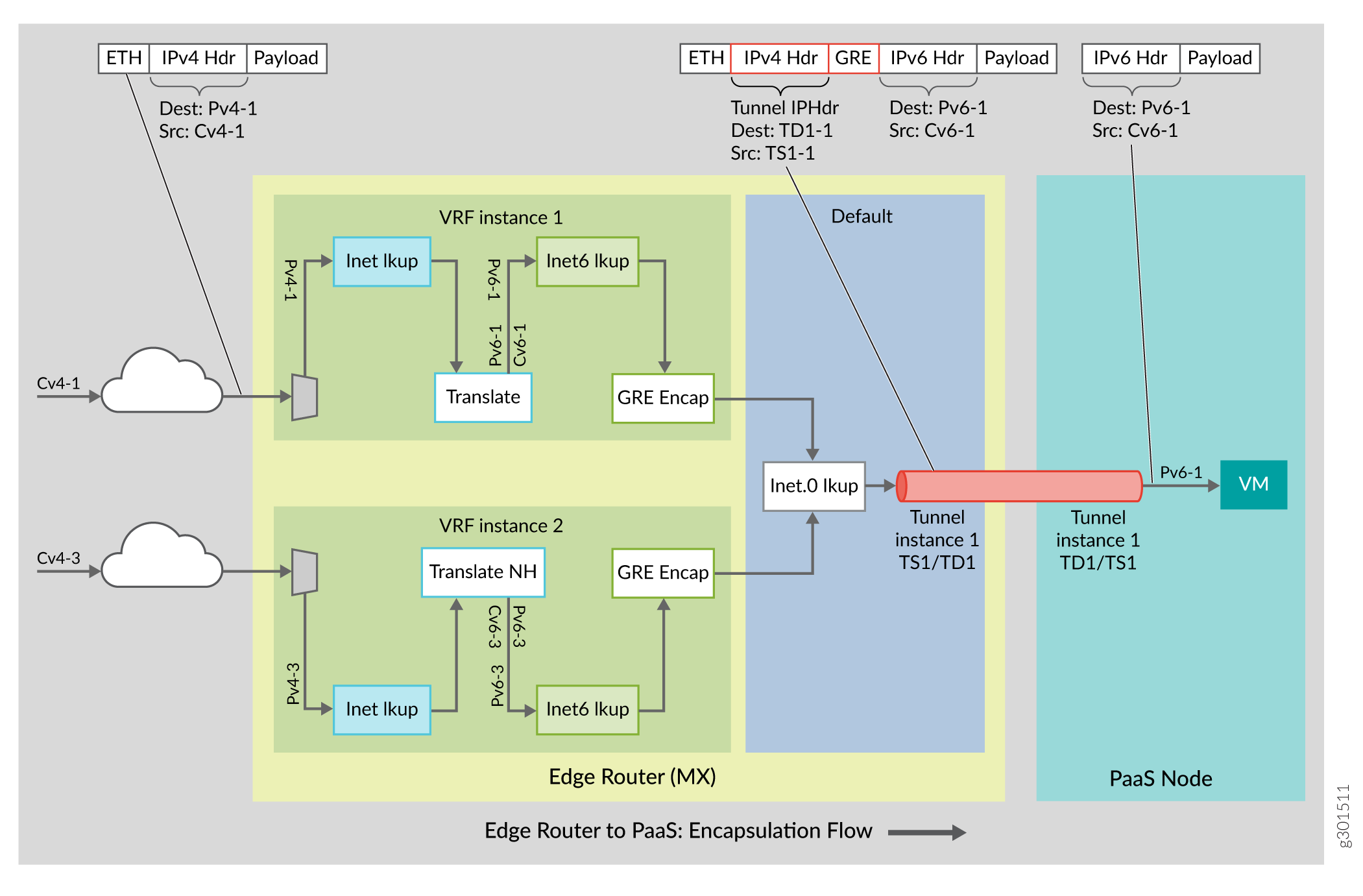
IPv4 packets are translated to IPv6 (IPv4 header replaced with new IPv6 header) based on translation rule defined per destination IPv4 prefix by the controller through the PRPD API. The customer VRF inet table is looked up with IPv4 destination for the translation.
GRE Tunnel encapsulation profile is defined for the translated IPv6 packets by the controller through the PRPD API . The translated IPv6 destination is looked up in the customer VRF inet6 table for tunnel encapsulation. Multiple prefixes may use the same tunnel.
After GRE tunnel encapsulation, outer IP tunnel destination is looked up in master instance inet.0 table for nexthop L2 encapsulation. .
The process is described in detail in the following sections.
- Understanding Profiles and Decoupling of Profiles
- Understanding the Forwarding Path
- IPv4-to-IPv6 Translation
- GRE Encapsulation
Understanding Profiles and Decoupling of Profiles
The edge router translates the packets based on the parameters defined in the translation profile. The parameters include translation type (IPv4 to IPv6 or IPv6 to IPv4), algorithm type, prefixes, and other related information.
The packets are encapsulated according to the parameters defined in the tunnel encapsulation profile.
In order to implement decoupling of the profiles, two separate routes are added by the data controller for translation and tunnel encapsulation:
- IPv4 RouteAdd() or RouteUpdate() programs the destination route in VRF inet table with the action as translate.
- IPv6 RouteAdd() or RouteUpdate() programs the translated IPv6 route in the VRF inet6 table with the action as GRE encapsulation (outer IPv4 tunnel header and GRE header)
Understanding the Forwarding Path
The edge router performs, three route lookups per IPv4 packet.
-
Route lookup in the VRF inet table—The IPv4 header is translated into IPv6 header. The controller adds the IPv4 route.
-
Route lookup in the VRF inet6 table—The translated IPv6 destination address is looked up to get the tunnel encapsulation profile which adds GRE and tunnel IPv4 header on top of the inner IPv6 header. The controller adds the IPv6 route.
-
Route lookup in master instance—The master instance inet table is looked up for routing the tunnel packets to the tunnel destination. IGP adds the route.
IPv4-to-IPv6 Translation
The translation details are as follows:
-
If IPv4 is fragmented or has IP options, it is discarded.
-
The packet type changes from IPv4 to IPv6.
-
ToS / DSCP fields are copied.
-
IPv6 Hop Limit is set to IPv4 TTL.
-
The payload protocol is copied (without error/ inconsistency checks).
-
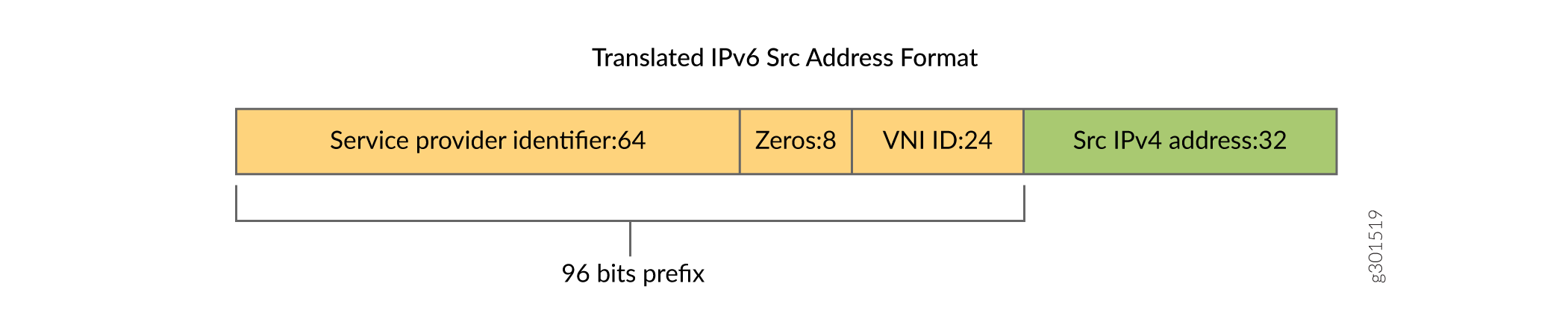
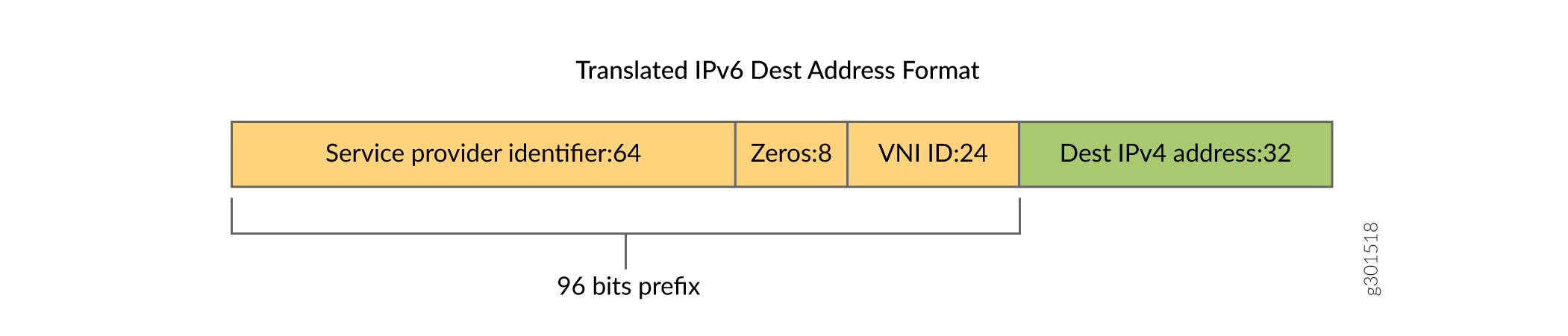
IPv6 packet destination address is set to TranslationDestinationIPv6.
-
96 most significant bits of the IPv6 packet source address are set to TranslationSourceIPv6Prefix.
-
32 least significant bits of the IPv6 packet source address are set to original packet IPv4 address
The translated IPv6 packet is illustrated as in Figure Figure 2
GRE Encapsulation
The controller defines the GRE tunnel encapsulation profile for the translated IPv6 destination through the PRPD API. The edge router looks up for the translated IPv6 destination in the customer VRF inet6 table for tunnel encapsulation. The details are as follows:
-
Outer GRE IPv4 tunnel header is added
-
GRE key is set to GREKey, which is configurable by the user
-
IPv4 destination is set to TunnelDestinationIPv4
-
IPv4 source is set to TunnelSourceIPv4
-
Note:
The number of tunnel encapsulation profiles can be less than or equal to the number of translation rules. By default, you can have a single GRE tunnel shared across multiple end customer VRFs. In PFE, there might be many GRE encapsulation routes that use the same profile parameters and thus the same tunnel nexthop. However, many translation routes may not use the same GRE route.
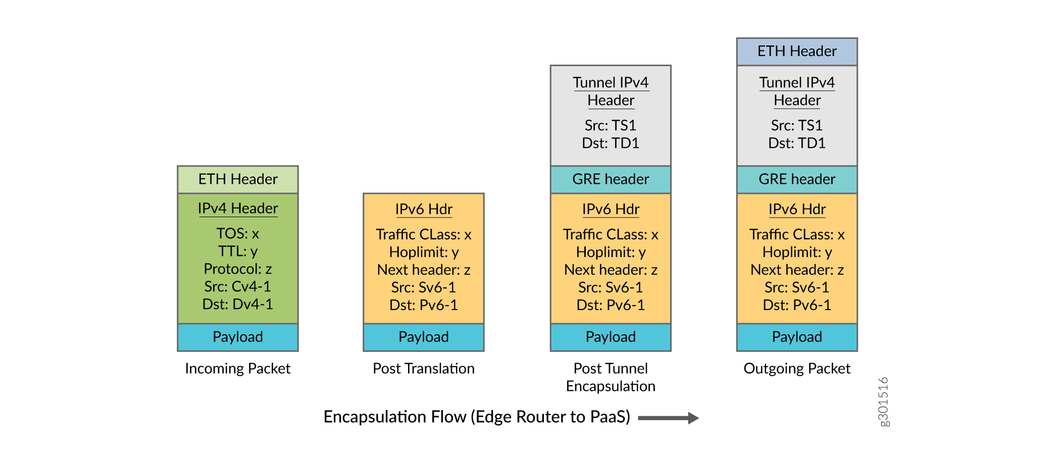
After encapsulation, the format of the packets at the edge router is as illustrated in Figure 3
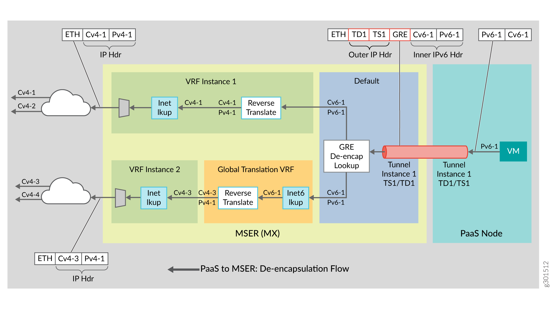
De-encapsulation Process (PaaS Server to Edge Router)
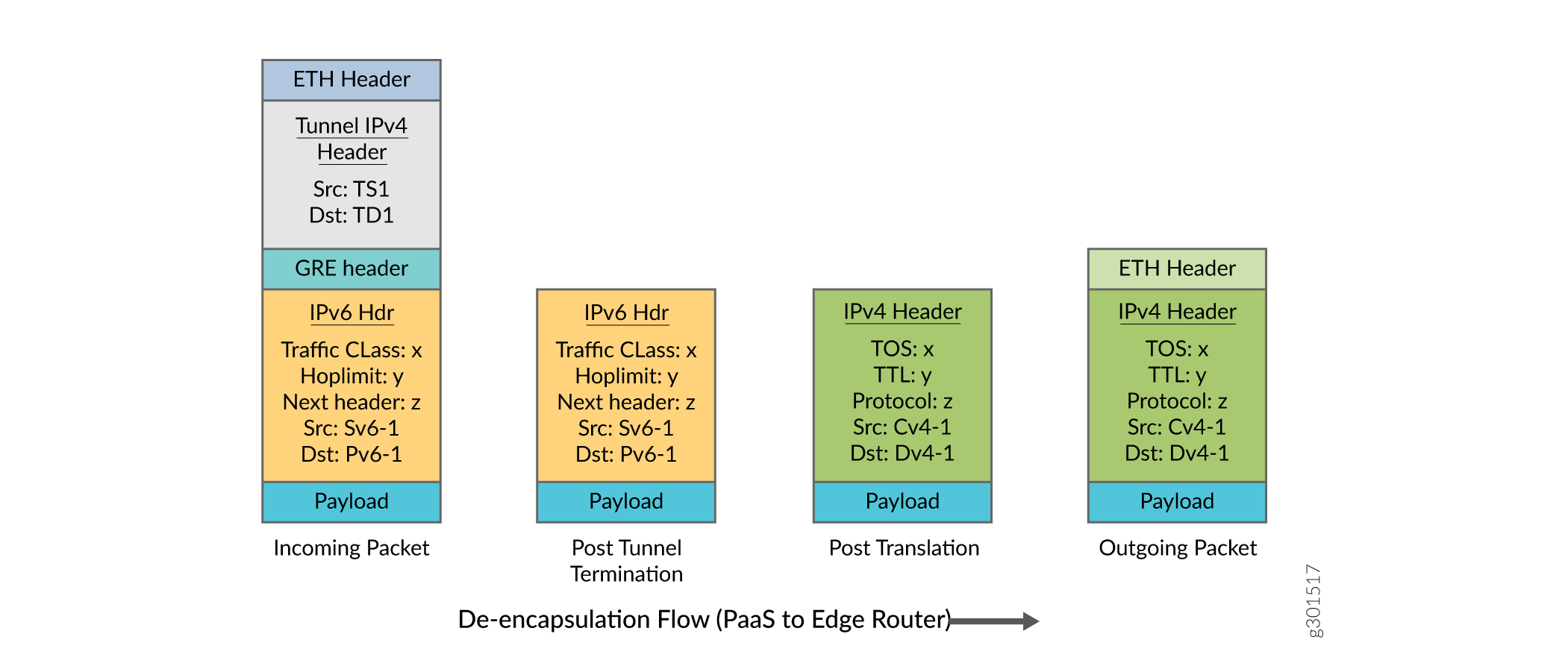
The flow of packets from the PaaS server to the edge router includes GRE de-encapsulation and reverse translation as illustrated in Figure 4.
The GRE encapsulated IPv6 packets received from the PaaS server, undergoes tunnel termination lookup, which de-encapsulates the GRE or IPv4 header and points to the VRF where the subsequent lookup for reverse translation happens. Based on the translation rule defined per destination IPv6 prefix by the controller, the IPv6 payload is translated (IPv6 header replaced with IPv4). After reverse translation, the translated address is looked up in the end customer VRF inet table to obtain the L2 encapsulation towards end customer network.
- Understanding Profiles and Decoupling of Profiles
- Understanding the Forwarding Path
- Understanding InnerIPv6Src address
- GRE De-encapsulation
- IPv6 to IPv4 Translation
Understanding Profiles and Decoupling of Profiles
Decoupling of de-encapsulation and reverse translation profiles is essential. The controller adds two separate routes for reverse translation and tunnel de-encapsulation through separate GRPC calls.
-
FlexibleTunnelAdd() programs the tunnel termination to point to the global translation VRF.
- IPv6 RouteAdd() or RouteUpdate() programs the inner destination IPv6 route in the VRF inet6 table in the global translation VRF with the action as reverse translation and targets the VRF as end customer VRF.
-
The end customer VRF inet route for the translated IPv4 address is programmed by the BGP protocol.
Understanding the Forwarding Path
GRE encapsulated IPv6 packet received from the PaaS server undergoes tunnel termination lookup which de-encapsulates the GRE or IPv4 header and points to the VRF where the subsequent lookup for reverse translation happens.
-
GRE tunnel termination lookup and tunnel de-encapsulation
-
De-encapsulation attributes form a lookup key GRE Key, Tunnel DestinationIPv4 address, Tunnel SourceIPv4 prefix.
-
Tunnel termination lookup identifies the customer VPN instance and removes the tunnel header (outer IPv4 header and GRE header).
-
The GRE header received from the PaaS server would have the key bit set and a 32-bit GRE key value. The forwarding lookup includes the GRE key along with the other lookup keys.
-
The packets are directed to the target VRF, which is the global translation VRF.
-
-
Reverse translation and end customer VRF identification
-
After tunnel de-encapsulation, the traffic needs to be routed to the end customer VRF. This routing is done using the translation route lookup on the InnerDestinationIPv6 address in a Global Translation VRF, a routing instance which the customer creates for holding the IPv6 translation routes.
You can use the InnerDestinationIPv6 address as a differentiator to identify the end customer VRF.
-
In the translation route (InnerDestinationIPv6) lookup, the reverse translation profile transforms the IPv6 header into IPv4 header and points to the end customer VRF. The lower 32 bits of the IPv6 address forms the translated IPv4 address.
-
-
Route lookup in end customer VRF inet table
-
The translated IPv4 address is looked up in the VRF inet table for routing the packet to the customer network.
-
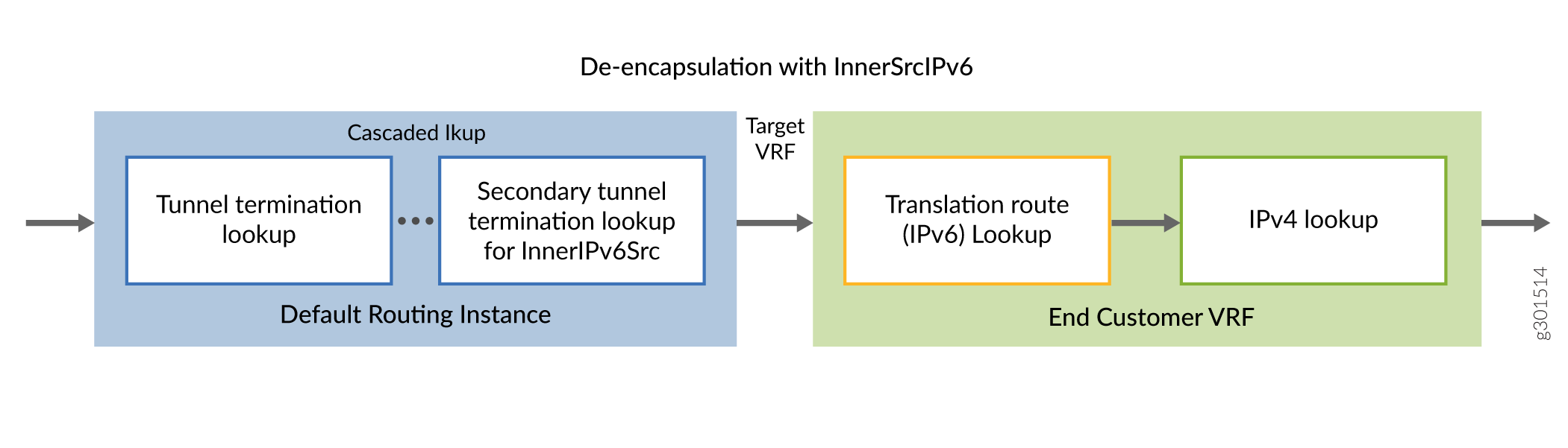
Understanding InnerIPv6Src address
The FlexibleTunnelAdd API also supports an optional parameter, InnerSourceIPv6 field. You can use this optional parameter to include the InnerSourceIPv6 address for terminating the GRE tunnel and identifying the customer VRF.
When the InnerSourceIPv6 address is used as a differentiator, you can configure tunnel termination lookup to point to the end customer VRF by passing the end customer VRF as the target VRF in the FlexibleTunnelAdd API. In this case, the translation routes (InnerDestinationIPv6) may be programmed into the respective end customer VRF table. However, enabling the optional InnerSourceIPv6 does not restrict from using the de-encapsulation flow with global translation VRF.
GRE De-encapsulation
The GRE de-encapsulation process involves the following steps:
-
Tunnel lookup and TargetVRF instance is determined using the lookup keys defined earlier.
-
The outer GRE header is discarded.
IPv6 to IPv4 Translation
The translation details are explained as follows:
-
Inner packet type changes from IPv6 to IPv4. If the inner packet type is not IPv6, then the packet is dropped, and the error counter is incremented.
-
Payload protocol field is copied without error or inconsistency checks.
-
TC field is copied into the DSCP field
-
IPv4 TTL is set to Inner IPv6 hop limit
- IPv4 destination address of the packet is derived from 32 least significant bits of the Inner IPv6 destination address
-
IPv4 source address of the packet is derived from 32 least significant bits of the Inner IPv6 source address
The structure of the packets received at the edge router is as illustrated in Figure Figure 7.
Change History Table
Feature support is determined by the platform and release you are using. Use Feature Explorer to determine if a feature is supported on your platform.