
Mapping of Address and Port with Translation (MAP-T)
Understanding Mapping of Address and Port with Translation (MAP-T)
This topic provides an overview of Mapping of Address and Port using Translation (MAP-T) feature. The topic lists the benefit to service providers when used as an inline service on MX Series routers with MPC and MIC interfaces.
- Benefits of Mapping of Address and Port with Translation (MAP-T)
- Mapping of Address and Port Using Translation (MAP-T) Terminology
- Mapping of Address and Port Using Translation (MAP-T) Functionality
- Mapping of Address and Port Using Translation (MAP-T) Supported and Unsupported Features
Benefits of Mapping of Address and Port with Translation (MAP-T)
The translation mode is advantageous in scenarios where the encapsulation overhead, or IPv6 operational practices rule out encapsulation (For example, use of IPv6-only servers, or reliance on IPv6 + protocol headers for traffic classification).
Mapping of Address and Port Using Translation (MAP-T) Terminology
-
Border Relay (BR)—MAP-T-enabled provider edge device in a MAP domain. A BR device has at least an IPv6-enabled interface and an IPv4 interface connected to the native IPv4 network.
-
MAP-T Customer Edge(CE)—MAP-T-enabled customer edge device in a MAP deployment.
-
MAP domain—One or more MAP-T CE devices and BR devices connected to the same virtual link.
-
Port Set ID (PSID)—Separate part of the transport layer port space that is denoted as port set ID.
-
Embedded Address (EA) Bits—EA-bits in the IPv6 address identify an IPv4 prefix or address or a shared IPv4 address and a port-set identifier.
-
Softwire—Tunnel between two IPv6 end-points to carry IPv4 packets or two IPv4 end-points to carry IPv6 packets.
-
Softwire Initiator (SI)—Softwire at the customer end that encapsulates native packets and tunnels them to a softwire concentrator at the service provider.
-
Softwire Concentrator (SC)—Softwire that decapsulates the packets received from a softwire initiator and sends them to their destination.
Mapping of Address and Port Using Translation (MAP-T) Functionality
The following figure illustrates a simple MAP-T deployment scenario.
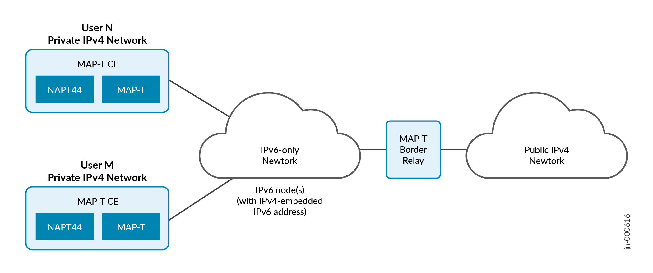
Figure 1 illustrates the MAP-T architecture. It consists of privately addressed IPv4 users (N and M) connected by means of MAP-T CEs to an IPv6 network that is equipped with one or more MAP-T BRs.
The MAP-T CE devices are dual stack and are capable of Network Address Port Translation (NAPT). The MAP-T CE devices connect to a MAP-T Border Relay (BR) device through an IPv6-only MAP-T network domain. The MAP-T BR device is dual stack and is connected to both a public IPv4 network and an IPv6 MAP-T network.
The MAP-T functionality is as follows:
-
The MAP-T CE devices are capable of NAPT. On receiving an IPv4 packet from the host, the MAP-T CE device performs NAT translation on the incoming IPv4 packets. The CE device translate the public IPv4 address and ports into an assigned IPv6 MAP source address. It sends the IPv6 packet with encoded IPv4 information toward the BR.
-
The MAP-T BR checks the source IPv6 MAP address against the configured MAP rules to ensure the correct public IPv4 address and port-range of the CE are encoded in the CE's source IPv6 MAP address. It translates the IPv6 packet into an IPv4 packet and forward it into the public domain.
In the reverse path, the incoming IPv4 packet is translated into an IPv6 packet according to MAP rules. The IPv4 destination address of the received packet is translated into an IPv6 MAP address of the CE.
In full reassembly of packets, the IPv4 fragments from the public IPv4 network are reassembled into a single IPv4 packet which is later translated into IPv6 and routed towards MAP-T CE device. The IPv6 fragments from MAP-T CE device are reassembled into a single IPv6 packet, which are translated to IPv4 packets, and forwarded to the IPv4 cloud.
The following table summarizes IPv4 full reassembly capabilities.
|
Maximum supported fragments per flow for full reassembly |
Maximum IP packet size (in bytes) that can be fully reassembled |
Maximum IP fragment size (in bytes) |
|---|---|---|
| 32 | 9000 | 9000 |
Mapping of Address and Port Using Translation (MAP-T) Supported and Unsupported Features
Junos OS supports the following MAP-T features and functionality:
-
TCP/UDP/ICMPv4/ICMPv6 traffic will be forwarded.
-
Support only next-hop style of configuration for MAP-T.
-
Support maximum packet size of 9192 bytes.
-
Support IPv4/IPv6 full reassembly.
The following features and functionality are not supported with the MAP-T feature:
-
IPv4/IPv6 partial reassembly is not supported.
-
IPv6 fragmentation is not supported.
-
Implementation of draft (non-standard) versions of RFC 7599 is not supported.
-
Interface-style MAP-T configuration is not supported.
-
MAP-T and non-MAP-T service in the same service-set is not supported.
Configuring Mapping of Address and Port using Translation (MAP-T)
This example shows you how to configure the MAP-T Border Relay (BR) solution using a next hop-based style of configuration.
To configure MAP-T:
For example:
chassis {
    fpc 4 {
        pic 0 {
            inline-services {
                bandwidth 100g;
            }
        }
    }
    fpc 5 {
        pic 0 {
            inline-services {
                bandwidth 100g;
            }
        }
    }
}
services {
    service-set sset1 {
        softwire-rules sw-rule1;
        next-hop-service {
            inside-service-interface si-4/0/0.1;
            outside-service-interface si-4/0/0.2;
        }
    }
    service-set sset2 {
        softwire-rules sw-rule1;
        next-hop-service {
            inside-service-interface si-5/0/0.1;
            outside-service-interface si-5/0/0.2;
        }
    }
    softwire {
        softwire-concentrator {
            map-t mapt-domain-1 {
                softwire-address 2001:db8:ffff::1;
                ipv4-prefix 192.0.2.0/24;
                mapt-prefix 2001:db8:1234:ab00::/56;
                ea-bits-len 16;
                psid-offset 4;
                psid-length 8;
                mtu-v6 9192;
                version-03;
                v4-reassembly;
                v6-reassembly;
            }
        }
        rule sw-rule1 {
            match-direction input;
            term t1 {
                then {
                    map-t mapt-domain-1;
                }
            }
        }
    }
}
interfaces {
    xe-0/1/1 {
        unit 0 {
            family inet6 {
                address 2001:db8::1/32 {
                    ndp 2001:db8:6434:0:00c0:0002:6400:3400 mac 00:11:22:33:44:55;
                }
            }
        }
    }
    xe-0/1/2 {
        unit 0 {
            family inet {
                address 100.1.1.1/24 {
                    arp 100.1.1.2 mac 00:11:22:33:44:55;
                }
            }
        }
    }
    si-4/0/0 {
        unit 1 {
            family inet;
            family inet6;
            service-domain inside;
        }
        unit 2 {
            family inet;
            family inet6;
            service-domain outside;
        }
    }
    si-5/0/0 {
        unit 1 {
            family inet6;
            service-domain inside;
        }
        unit 2 {
            family inet;
            family inet6;
            service-domain outside;
        }
    }
}
MAP-T with ECMP Support
This configuration deploys high‑scale MAP‑T services with inline processing, multiple MAP‑T domains, and per‑flow load balancing.
Understanding MAP-T VRF-Based Deployment
When you deploy Mapping of Address and Port using Translation (MAP-T), you can operate stateless IPv4–IPv6 translation across an IPv6-only core while keeping subscriber and Internet traffic in separate VPN routing and forwarding (VRF) instances, using next-hop style inline services. You map customer premises equipment (CPE)–facing IPv6 traffic and Internet-facing IPv4 traffic to distinct routing instances, satisfy specific route-leak requirements for MAP-T domain prefixes, and support Transmission Control Protocol (TCP), User Datagram Protocol (UDP), and selected Internet Control Message Protocol (ICMP) types and codes within a defined MAP-T maximum transmission unit (MTU). You can provision CPE MAP-T parameters dynamically through Dynamic Host Configuration Protocol version 6 (DHCPv6) option 95, enable inline IP reassembly to handle fragmented IPv4 and IPv6 packets, and use equal-cost multipath (ECMP) with per-flow load balancing to scale MAP-T traffic across multiple service paths, all within documented scaling and configuration constraints.
Benefits of MAP-T VRF-based deployment
-
Maintain clear separation of subscriber and Internet routing policies by placing CPE-facing and Internet-facing traffic in different VRFs, while still enabling MAP-T lookups through controlled route leaking of MAP-T domain prefixes.
-
Extend MAP-T deployments to VRF-based topologies (for example, per-subscriber or per-service routing instances) without changing MAP-T translation behavior.
-
Centralize delivery of MAP-T domain parameters to CPE by using DHCPv6 option 95, reducing per-device configuration effort.
Overview
When you extend MAP-T to operate in VRF-based environments, you place the CPE-facing IPv6 traffic and the Internet-facing IPv4 traffic into separate routing instances and then explicitly steer both directions of the flow through an inline services MAP-T service set. You configure next-hop style softwire rules under the <codeph>services softwire</codeph> hierarchy and bind them to a service set that references inside and outside service interfaces. You then add the inside service interface to the subscriber VRF and the outside service interface to the Internet or core VRF, so that IPv6 packets from subscribers and IPv4 packets toward the Internet both traverse the same stateless MAP-T domain. As a result, you preserve VRF separation while still performing consistent IPv4–IPv6 translation on the border relay (BR).
To make MAP-T lookups succeed in this split-VRF model, you must satisfy specific routing requirements in each VRF. You configure the MAP-T domain under <codeph>services softwire softwire-concentrator map-t</codeph>, defining the default mapping rule (DMR) IPv6 prefix, MAP-T IPv4 prefix, embedded address (EA) bits, port set identifier (PSID) parameters, and MTU. You then ensure that the DMR IPv6 prefix is reachable in the Internet-facing VRF (for IPv6-to-IPv4 lookups) and that the MAP-T IPv4 prefix is reachable in the subscriber VRF (for IPv4-to-IPv6 lookups), typically by leaking the relevant routes between VRFs or by installing appropriate static routes. When you do this correctly, the BR performs stateless address and port mapping as defined in Request for Comments (RFC) 7599, RFC 7598, and RFC 6145 in both directions, including translation of supported TCP, UDP, and ICMP types and codes within the configured MAP-T MTU.
By attaching IP reassembly rules to the same service set that performs MAP-T and enabling IPv4 reassembly and IPv6 reassembly under the MAP-T domain, you cause fragmented IPv4 and IPv6 packets to be reassembled before translation, so that the BR applies the stateless mapping correctly. When you create multiple service sets with identical MAP-T domain configuration and install static routes with multiple next hops that point to different service interfaces, you allow MAP-T traffic to use ECMP paths across several inline services processing elements. Combined with per-flow load-balancing policies on the forwarding table, this distributes MAP-T flows across multiple service paths without reordering individual flows, while still operating within documented scaling limits.
DHCPv6-based MAP-T provisioning
You use DHCPv6 option 95 to provision CPE MAP-T parameters dynamically so that the CPE and
the BR share a consistent view of the MAP-T
domain. On the device, you configure an IPv6
address-assignment pool and attach a dhcp-attributes statement that
includes option 95 hex-string, encoding the MAP-T IPv6 and IPv4 prefixes,
EA-bits length, PSID offset and length, and DMR prefix and BR address as defined in RFC
7598. You then bind this pool to subscriber interfaces through the dhcp-local-server
dhcpv6 group configuration, so that when a CPE brings up a DHCPv6 session, it
receives both its delegated IPv6 prefix and the MAP-T parameters in a single exchange.
Because the MAP-T option 95 content must reflect the exact MAP-T domain configuration on
the BR, you must keep the encoded hex-string synchronized with the parameters that you
define under services softwire softwire-concentrator map-t. If you change
EA bits, PSID values, or prefixes in the MAP-T domain but do not update the DHCPv6 option 95
string, the CPE computes different IPv4-embedded IPv6 addresses and port ranges than the BR
expects, which causes translation failures even though the control plane appears healthy. By
validating the option 95 encoding against the MAP-T domain and by using operational commands
to verify softwire and inline service statistics, you ensure that dynamically provisioned
CPEs participate in the same stateless mapping scheme as the BR, enabling large-scale,
consistent MAP-T deployments across VRF-separated subscriber and Internet environments.
Configuring Mapping of Address and Port using Translation (MAP-T) with VRF and DHCPv6
This configuration enables MAP‑T provisioning using DHCPv6 in a VRF‑based deployment. Here, the Junos OS device functions as a DHCPv6 local server that delivers MAP‑T provisioning parameters to subscriber CPEs. IPv4‑over‑IPv6 translation is performed on the CPE.
To enable MAP‑T provisioning using DHCPv6 in a VRF‑based deployment: