Inline NAT
Inline Network Address Translation Overview
Inline NAT uses the capabilities of the MPC line card, eliminating the need for a services card for NAT. Consequently, you can achieve line-rate, low-latency address translations (up to 120 Gbps per slot). The current implementation provides:
-
1:1 static address mapping.
-
Bidirectional mapping - source NAT for outbound traffic and destination NAT for inbound traffic.
-
No limit on number of flows.
-
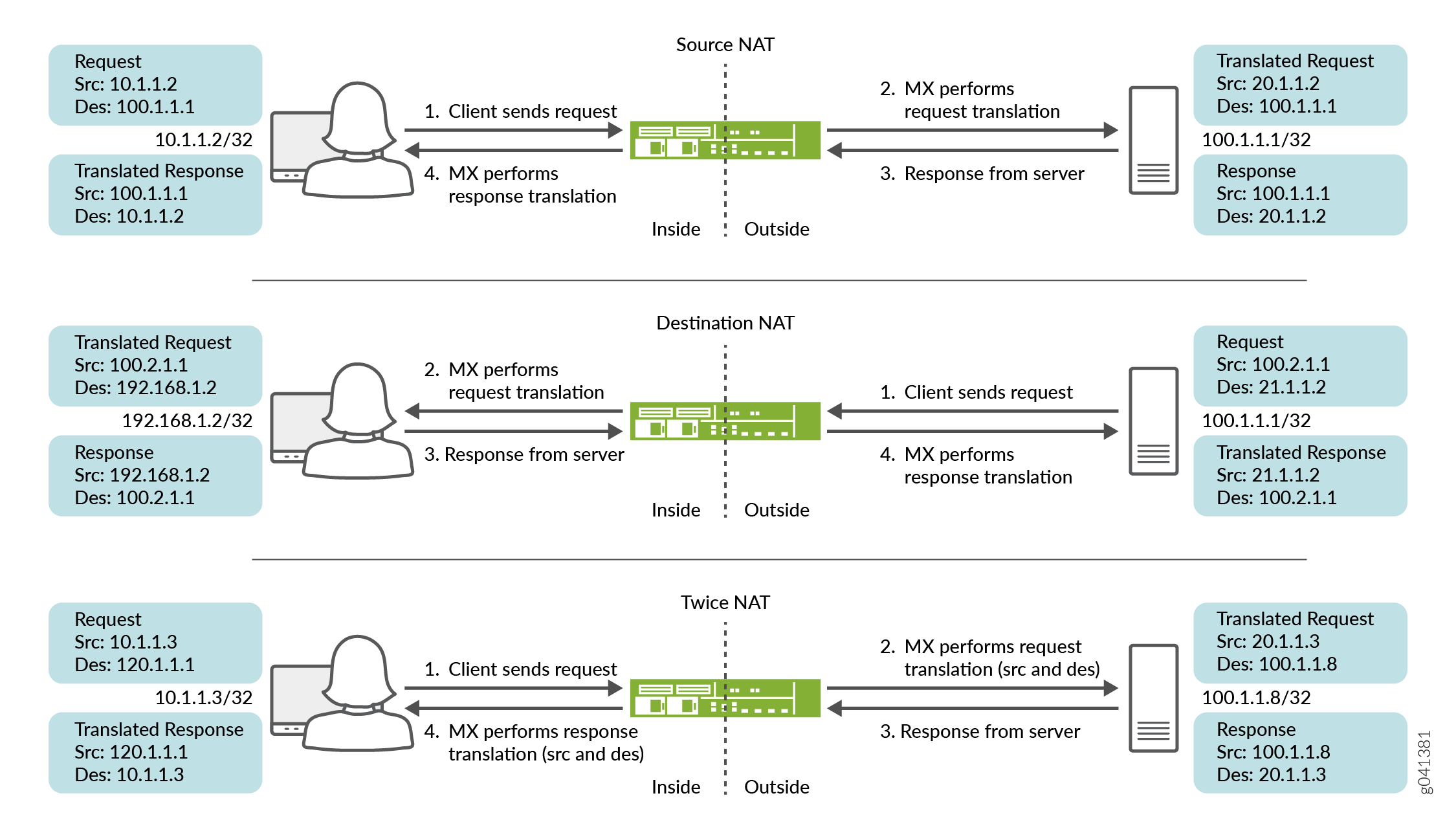
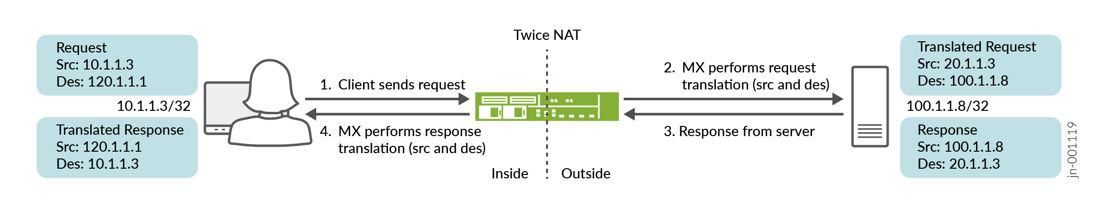
Support for Source, destination, and twice NAT, as shown in Figure 1. Inline NAT supports the translation type
basic-nat44. Starting in Junos OS Release 15.1R1, inline NAT also supportstwice-basic-nat-44. -
Support for hairpinning.
To configure inline NAT, you define your service interface as
type si- (service-inline) interface. You must also reserve
adequate bandwidth for the inline interface. This enables you to configure
both interface or next-hop service-sets used for NAT. The si- interface serves as a “virtual service PIC”.
-
Only static NAT is supported. Port translation, dynamic NAT, and ALGs are not supported. Hence, applications such as SIP or FTP Active Mode which require advanced processing for NAT do not function. An MS-MPC, MS-MIC, MS-DPC, or MS-PIC is still needed for any stateful-firewall processing, ALG support, and dynamic port translation.
-
Inline NAT does not support sampling or logging of packets.
Benefits of Inline NAT
-
Eliminates the need for a services card
-
Supports more NAT flows than a services card
See Also
Example: Configuring Inline Network Address Translation—Interface-Based Method
This configuration example illustrates how to configure interface-based inline network
address translation (NAT) on MX Series devices using si-
(service-inline) interfaces with interface-style service-sets.
This topic covers:
- Requirements
- Overview and Topology
- Configuration for Inline Network Address Translation
- Verification
- Configuration for Twice NAT
- Configuration for Destination NAT
Requirements
This example uses the following hardware and software components:
-
MX Series router with a Modular Port Concentrator (MPC) line card
-
Junos OS Release 11.4R1 or higher
Overview and Topology
As of Junos OS Release 11.4R1, MPC line cards can perform some services without the need of a dedicated services card, such as an MS-MPC. Inline services generally provide better performance than using a services card, however their functionality tends to be more basic. For example, inline NAT supports only static NAT.
In this example, an MX Series device with an MPC line card provides inline source NAT services to traffic flowing between two end hosts. The topology for this scenario is shown in Figure 2
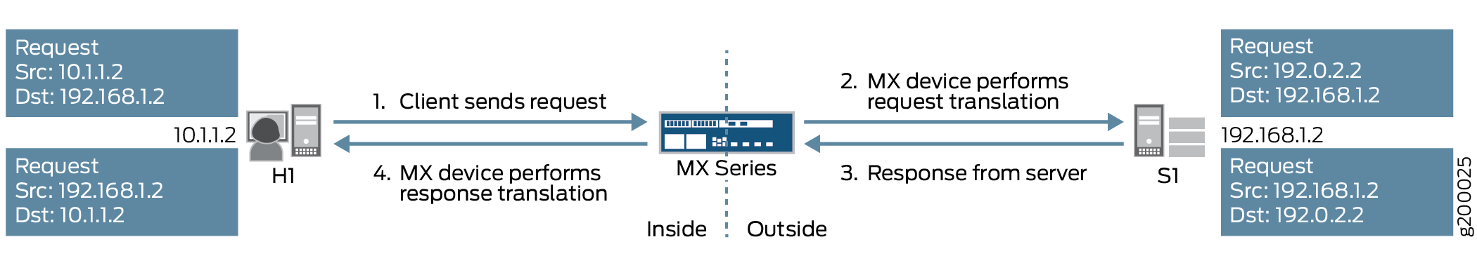
As shown in the figure, host H1 sends traffic towards server S1. The MX Series device performs source NAT to translate H1’s source IP address from 10.1.1.2 to 192.0.2.2. Server S1 then sends return traffic to host H1 using the destination IP address 192.0.2.2, and the MX Series device reverts H1’s IP address back to 10.1.1.2.
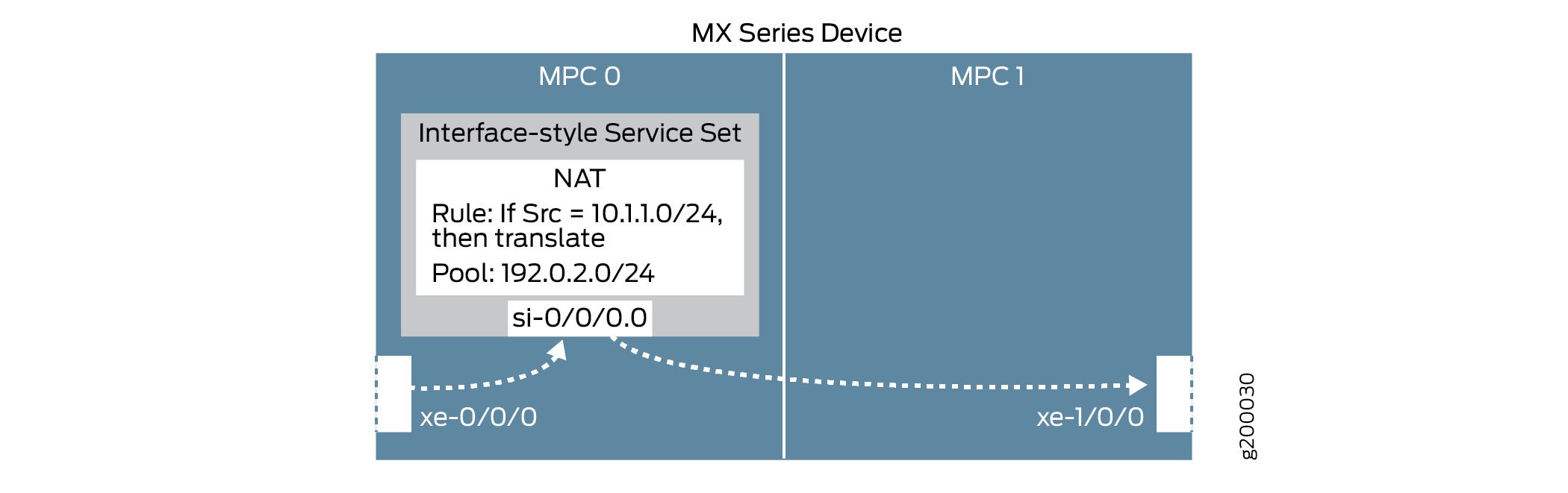
The following configuration elements are used in this scenario:
-
Inline service interface—a virtual interface that resides on the Packet Forwarding Engine of the MPC. To access services, traffic flows in and out of these
si-(service-inline) interfaces. -
Service set—defines the service(s) to be performed, and identifies which inline interface(s) will feed traffic into and out of the service set. There are two ways to implement service sets:
-
Interface-style—an interface-based method, where packets arriving at an interface are forwarded through the inline service.
-
Next-hop-style—a route-based method, where static routes are used to forward packets destined for a specific destination through the inline service.
This example uses the interface-style service set.
-
-
NAT rule—uses an if-then structure (similar to firewall filters) to define matching conditions and then apply address translation to the matching traffic.
-
NAT pool—a user-defined set of IP addresses that are used by the NAT rule for translation.
These elements come together as shown in Figure 3
Configuration for Inline Network Address Translation
To configure inline NAT using an interface-style service set, perform these tasks:
- CLI Quick Configuration
- Enable Inline Services and Create an Inline Interface
- Configure NAT Rule and Pool
- Configure the (Interface-style) Service Set
- Configure Physical Interfaces
CLI Quick Configuration
To quickly configure this example, copy the following commands, paste them into a text file, remove any line breaks, change any details necessary to match your network configuration, and then copy and paste the commands into the CLI at the [edit] hierarchy level.
## Enable inline services, create an si- interface, reserve bandwidth ##
set chassis fpc 0 pic 0 inline-services bandwidth 1g
set interfaces si-0/0/0 unit 0 family inet
## Configure a NAT rule and pool ##
set services nat rule SRC-NAT1 match-direction input
set services nat rule SRC-NAT1 term r1 from source-address 10.1.1.0/24
set services nat rule SRC-NAT1 term r1 then translated translation-type basic-nat44
set services nat rule SRC-NAT1 term r1 then translated source-pool p1
set services nat pool p1 address 192.0.2.0/24
## Configure the (interface-style) service set ##
set services service-set INT-STYLE-SS-NAT1 nat-rules SRC-NAT1
set services service-set INT-STYLE-SS-NAT1 interface-service service-interface si-0/0/0.0
## Configure interfaces ##
set interfaces xe-0/0/0 unit 0 family inet address 10.1.1.1/24
set interfaces xe-0/0/0 description INSIDE
set interfaces xe-1/0/0 unit 0 family inet address 192.168.1.1/24
set interfaces xe-1/0/0 description OUTSIDE
set interfaces xe-0/0/0 unit 0 family inet service input service-set INT-STYLE-SS-NAT1
set interfaces xe-0/0/0 unit 0 family inet service output service-set  INT-STYLE-SS-NAT1
Enable Inline Services and Create an Inline Interface
Step-by-Step Procedure
Enable inline services for the relevant FPC slot and PIC slot, and define the amount of bandwidth to dedicate for inline services.
The FPC and PIC settings here will create and map to an
si-interface.[edit chassis fpc 0 pic 0] user@MX# set inline-services bandwidth 1g
On the
si-interface, specify the protocol family (or families) that will need NAT services.Note:The FPC and PIC settings here must match the settings defined above.
[edit interfaces si-0/0/0]
user@MX# set unit 0 family inet
Configure NAT Rule and Pool
Step-by-Step Procedure
Configure a NAT rule that matches on traffic arriving at the MX device from H1’s subnet (10.1.1.0/24), translates it using basic IPv4 NAT, and uses an IP address from pool
p1.[edit services nat] user@MX# set rule SRC-NAT1 match-direction input user@MX# set rule SRC-NAT1 term r1 from source-address 10.1.1.0/24 user@MX# set rule SRC-NAT1 term r1 then translated translation-type basic-nat44 user@MX# set rule SRC-NAT1 term r1 then translated source-pool p1
Configure the NAT pool.
[edit services nat]
user@MX# set pool p1 address 192.0.2.0/24
Configure the (Interface-style) Service Set
Step-by-Step Procedure
Configure a service set that uses the inline NAT service (
nat-rules), and the inline interface defined above. Use theinterface-serviceparameter to specify that this is an interface-style service set.Traffic will flow into and out of the
si-interface to access the inline NAT service.[edit services] user@MX# set service-set INT-STYLE-SS-NAT1 nat-rules SRC-NAT1 user@MX# set service-set INT-STYLE-SS-NAT1 interface-service service-interface si-0/0/0.0
Configure Physical Interfaces
Step-by-Step Procedure
Configure the physical interfaces.
[edit interfaces]
user@MX# set xe-0/0/0 unit 0 family inet address 10.1.1.1/24
user@MX# set xe-0/0/0 description INSIDE
user@MX# set xe-1/0/0 unit 0 family inet address 192.168.1.1/24
user@MX# set xe-1/0/0 description OUTSIDE
On the ’inside’ interface, specify that traffic will be sent through the service set defined above.
[edit interfaces xe-0/0/0 unit 0]
user@MX# set family inet service input service-set INT-STYLE-SS-NAT1
user@MX# set family inet service output service-set  INT-STYLE-SS-NAT1
Results
chassis {
    fpc 0 {
        pic 0 {
            inline-services {
                bandwidth 1g;
            }
        }
    }
}

services {
    service-set INT-STYLE-SS-NAT1 {
        nat-rules SRC-NAT1;
        interface-service {
            service-interface si-0/0/0.0;
        }
    }
    nat {
        pool p1 {
            address 192.0.2.0/24;
        }
        rule SRC-NAT1 {
            match-direction input;
            term r1 {
                from {
                    source-address {
                        10.1.1.0/24;
                    }
                }
                then {
                    translated {
                        source-pool p1;
                        translation-type {
                            basic-nat44;
                        }
                    }
                }
            }
        }
    }
}

interfaces {
    si-0/0/0 {
        unit 0 {
            family inet;
        }
    }
    xe-0/0/0 {
        description INSIDE;
        unit 0 {
            family inet {
                service {
                    input {
                        service-set INT-STYLE-SS-NAT1;
                    }
                    output {
                        service-set INT-STYLE-SS-NAT1;
                    }
                }
                address 10.1.1.1/24;
            }
        }
    }
    xe-1/0/0 {
        description OUTSIDE;
        unit 0 {
            family inet {
                address 192.168.1.1/24;
            }
        }
    }
}
Verification
Confirm that the configuration is working properly.
Verifying Reachability from Host H1 to Server S1
Purpose
Verify reachability between H1 and S1.
Action
On host H1, verify that the host can ping server S1.
user@H1> ping 192.168.1.2 count 5
PING 192.168.1.2 (192.168.1.2): 56 data bytes
64 bytes from 192.168.1.2: icmp_seq=0 ttl=63 time=0.991 ms
64 bytes from 192.168.1.2: icmp_seq=1 ttl=63 time=14.186 ms
64 bytes from 192.168.1.2: icmp_seq=2 ttl=63 time=3.016 ms
64 bytes from 192.168.1.2: icmp_seq=3 ttl=63 time=3.742 ms
64 bytes from 192.168.1.2: icmp_seq=4 ttl=63 time=4.748 ms

--- 192.168.1.2 ping statistics ---
5 packets transmitted, 5 packets received, 0% packet loss
round-trip min/avg/max/stddev = 0.991/5.337/14.186/4.593 ms
Meaning
H1 can successfully reach S1.
Verifying Address Translation
Purpose
Verify that address translation is working correctly.
Action
On the MX device, verify that the inline NAT configuration details have been applied correctly.
user@MX> show services inline nat pool
Interface: si-0/0/0, Service set: INT-STYLE-SS-NAT1
  NAT pool: p1, Translation type: BASIC NAT44
    Address range: 192.0.2.0-192.0.2.255
    NATed packets: 5, deNATed packets: 5, Errors: 0
On server S1, verify that the server is receiving the pings from H1’s NAT-translated source IP address (192.0.2.2).
Issue the command below, and send pings again from H1.
Note:For this setup, another MX device is used to represent server S1 to enable monitoring of the inbound traffic.
user@S1> monitor traffic interface xe-1/1/1 no-resolve
verbose output suppressed, use <detail> or <extensive> for full protocol decode
Address resolution is OFF.
Listening on xe-1/1/1, capture size 96 bytes

23:28:28.577377  In IP 192.0.2.2 > 192.168.1.2: ICMP echo request, id 3293, seq 0, length 64
23:28:28.577405 Out IP 192.168.1.2 > 192.0.2.2: ICMP echo reply, id 3293, seq 0, length 64
23:28:29.579253  In IP 192.0.2.2 > 192.168.1.2: ICMP echo request, id 3293, seq 1, length 64
23:28:29.579278 Out IP 192.168.1.2 > 192.0.2.2: ICMP echo reply, id 3293, seq 1, length 64
23:28:30.579275  In IP 192.0.2.2 > 192.168.1.2: ICMP echo request, id 3293, seq 2, length 64
23:28:30.579302 Out IP 192.168.1.2 > 192.0.2.2: ICMP echo reply, id 3293, seq 2, length 64
23:28:31.580279  In IP 192.0.2.2 > 192.168.1.2: ICMP echo request, id 3293, seq 3, length 64
23:28:31.580305 Out IP 192.168.1.2 > 192.0.2.2: ICMP echo reply, id 3293, seq 3, length 64
23:28:32.581266  In IP 192.0.2.2 > 192.168.1.2: ICMP echo request, id 3293, seq 4, length 64
23:28:32.581293 Out IP 192.168.1.2 > 192.0.2.2: ICMP echo reply, id 3293, seq 4, length 64
^C
10 packets received by filter
0 packets dropped by kernel
Meaning
Step 1 above confirms that the inline NAT service parameters and interface-style service set are correctly implemented. Step 2 above confirms that server S1 is correctly receiving H1’s pings from its NAT-translated source IP address.
Configuration for Twice NAT
To configure Twice NAT using an interface-style service set, perform these tasks:
CLI Quick Configuration
To quickly configure this example, copy the following commands, paste them into a text file, remove any line breaks, change any details necessary to match your network configuration, and then copy and paste the commands into the CLI at the [edit] hierarchy level.
## Configure a NAT rule and pool ##
set services nat pool dst-pool-p1 address 100.1.1.2/32
set services nat pool dst-pool-p2 address 100.1.1.4/32
set services nat pool src-pool-p2 address 20.0.0.0/8
set services nat allow-overlapping-nat-pools
set services nat rule TWICE_rule_1 match-direction output
set services nat rule TWICE_rule_1 term TWICE_rule_1_term_1 from source-address 10.0.0.0/8
set services nat rule TWICE_rule_1 term TWICE_rule_1_term_1 from destination-address 120.1.1.2/32
set services nat rule TWICE_rule_1 term TWICE_rule_1_term_1 then translated source-pool src-pool-p1
set services nat rule TWICE_rule_1 term TWICE_rule_1_term_1 then translated destination-pool dst-pool-p1
set services nat rule TWICE_rule_1 term TWICE_rule_1_term_1 then translated translation-type twice-basic-nat-44
set services nat rule TWICE_rule_1 term TWICE_rule_1_term_2 from source-address 10.0.0.0/8
set services nat rule TWICE_rule_1 term TWICE_rule_1_term_2 from destination-address 120.1.1.4/32
set services nat rule TWICE_rule_1 term TWICE_rule_1_term_2 then translated source-pool src-pool-p2
set services nat rule TWICE_rule_1 term TWICE_rule_1_term_2 then translated destination-pool dst-pool-p2
set services nat rule TWICE_rule_1 term TWICE_rule_1_term_2 then translated translation-type twice-basic-nat-44
set services nat rule-set TWICE_NAT_RS1 rule TWICE_rule_1
set services service-set TWICE_SS_1 nat-rule-sets TWICE_NAT_RS1
set services service-set TWICE_SS_1 interface-service service-interface si-2/0/0
## Configure interfaces ##
set interfaces si-2/0/0 unit 0 family inet filter input log_filer
set interfaces xe-2/0/0 unit 0 family inet address 10.1.1.251/16
set interfaces xe-2/0/1 unit 0 family inet service input service-set TWICE_SS_1 service-filter TWICE_SF_in
set interfaces xe-2/0/1 unit 0 family inet service output service-set TWICE_SS_1 service-filter TWICE_SF_out
set interfaces xe-2/0/1 unit 0 family inet address 100.1.1.251/16
## Configure firewall filters ##
set firewall family inet service-filter TWICE_SF_in term SF_R1_term_1 from source-address 100.1.1.2/32
set firewall family inet service-filter TWICE_SF_in term SF_R1_term_1 then service
set firewall family inet service-filter TWICE_SF_in term SF_R1_term_2 from source-address 100.1.1.4/32
set firewall family inet service-filter TWICE_SF_in term SF_R1_term_2 then service
set firewall family inet service-filter TWICE_SF_in term default then count non-matching-packets-in
set firewall family inet service-filter TWICE_SF_out term SF_R1_out_term_1 from destination-address 120.1.1.2/32
set firewall family inet service-filter TWICE_SF_out term SF_R1_out_term_1 then service
set firewall family inet service-filter TWICE_SF_out term SF_R1_out_term_2 from destination-address 120.1.1.4/32
set firewall family inet service-filter TWICE_SF_out term SF_R1_out_term_2 then service
set firewall family inet service-filter TWICE_SF_out term default then count non-matching-packets-out
set firewall family inet service-filter TWICE_SF_out term default then skip
Configure the (Interface-style) Service Set
Configure a service set that uses the Twice NAT service (
nat-rules), aUse theinterface-serviceparameter to specify that this is an interface-style service set.[edit services] user@MX# set service-set TWICE_SS_1 nat-rule-sets TWICE_NAT_RS1 user@MX# set service-set TWICE_SS_1 interface-service service-interface si-2/0/0
Configure Physical Interfaces
Step-by-Step Procedure
Configure the physical interfaces.
[edit interfaces]
user@MX# set si-2/0/0 unit 0 family inet filter input log_filer
user@MX# set xe-2/0/0 unit 0 family inet address 10.1.1.251/16
user@MX# set xe-2/0/1 unit 0 family inet service input service-set TWICE_SS_1 service-filter TWICE_SF_in
user@MX# set xe-2/0/1 unit 0 family inet service output service-set TWICE_SS_1 service-filter TWICE_SF_out
user@MX# set xe-2/0/1 unit 0 family inet address 100.1.1.251/16
On the interface, specify that traffic will be sent through the service set defined above.
[edit interfaces]
user@MX# set xe-2/0/1 unit 0 family inet service input service-set TWICE_SS_1 service-filter TWICE_SF_in
user@MX# set xe-2/0/1 unit 0 family inet service output service-set TWICE_SS_1 service-filter TWICE_SF_out
Configure the firewall filter options to direct the traffic to the
siinterface.[edit firewall] user@MX# set family inet service-filter TWICE_SF_in term SF_R1_term_1 from source-address 100.1.1.2/32 user@MX# set family inet service-filter TWICE_SF_in term SF_R1_term_1 then service user@MX# set family inet service-filter TWICE_SF_in term SF_R1_term_2 from source-address 100.1.1.4/32 user@MX# set family inet service-filter TWICE_SF_in term SF_R1_term_2 then service user@MX# set family inet service-filter TWICE_SF_in term default then count non-matching-packets-in user@MX# set family inet service-filter TWICE_SF_out term SF_R1_out_term_1 from destination-address 120.1.1.2/32 user@MX# set family inet service-filter TWICE_SF_out term SF_R1_out_term_1 then service user@MX# set family inet service-filter TWICE_SF_out term SF_R1_out_term_2 from destination-address 120.1.1.4/32 user@MX# set family inet service-filter TWICE_SF_out term SF_R1_out_term_2 then service user@MX# set family inet service-filter TWICE_SF_out term default then count non-matching-packets-out user@MX# set family inet service-filter TWICE_SF_out term default then skip
Configuration for Destination NAT
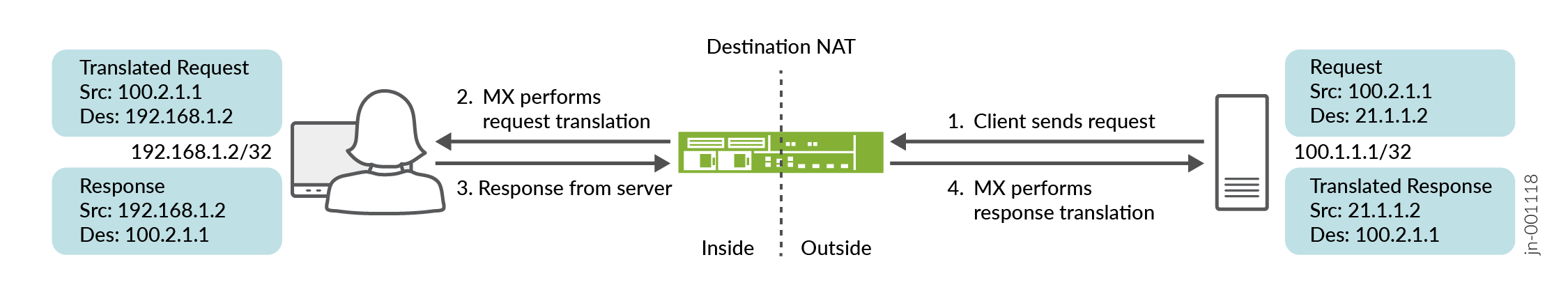
To configure Destination NAT using an interface-style service set, perform these tasks:
- CLI Quick Configuration
- Enable Inline Services
- Configure the (Interface-style) Service Set
- Configure Physical Interfaces
CLI Quick Configuration
To quickly configure this example, copy the following commands, paste them into a text file, remove any line breaks, change any details necessary to match your network configuration, and then copy and paste the commands into the CLI at the [edit] hierarchy level.
## Enable inline services, create an si- interface ##
set chassis fpc 2 pic 0 inline-services
set chassis fpc 2 pic 1 inline-services
set services service-set DANT44_SS_1 nat-rule-sets DNAT44_RS_1
set services service-set DANT44_SS_1 interface-service service-interface si-2/0/0.0
## Configure a NAT rule  ##
set services nat rule DNAT44_rule_1 match-direction output
set services nat rule DNAT44_rule_1 term DNAT44_R1_term_1 from destination-address 21.1.1.2/32
set services nat rule DNAT44_rule_1 term DNAT44_R1_term_1 then translated destination-prefix 192.168.1.2/32
set services nat rule DNAT44_rule_1 term DNAT44_R1_term_1 then translated translation-type dnat-44
set services nat rule-set DNAT44_RS_1 rule DNAT44_rule_1
##  Configure interfaces (and the interface-style) and service filters ##
set interfaces si-2/0/0 unit 0 family inet
set interfaces xe-2/0/0 unit 0 family inet address 100.2.1.2/24
set interfaces xe-2/0/1 unit 0 family inet service input service-set DANT44_SS_1 service-filter SF_in
set interfaces xe-2/0/1 unit 0 family inet service output service-set DANT44_SS_1 service-filter SF_out
set interfaces xe-2/0/1 unit 0 family inet address 192.168.1.251/24
##  Configure the firewall filter options and static route options##
set firewall family inet service-filter SF_in term SF_in_term1 from source-address 192.168.1.2/32
set firewall family inet service-filter SF_in term SF_in_term1 then service
set firewall family inet service-filter SF_out term SF_out_term1 from destination-address 21.1.1.2/32
set firewall family inet service-filter SF_out term SF_out_term1 then service
set routing-options static route 21.1.0.0/16 next-hop 100.2.1.2
Enable Inline Services
Enable inline services for the relevant FPC slot and PIC slot.
The FPC and PIC settings here will create and map to an
si-interface.[edit chassis fpc 2 pic 0] user@MX# set inline-services
[edit chassis fpc 2 pic 1]
user@MX# set inline-services
Configure the (Interface-style) Service Set
Configure a service set that uses the Destination NAT service (
nat-rules), aUse theinterface-serviceparameter to specify that this is an interface-style service set.[edit services service-set] user@MX# set DANT44_SS_1 nat-rule-sets DNAT44_RS_1 user@MX# set DANT44_SS_1 DANT44_SS_1 interface-service service-interface si-2/0/0.0
Configure Physical Interfaces
Configure the physical interfaces.
[edit interfaces]
user@MX# set si-2/0/0 unit 0 family inet
user@MX# set xe-2/0/0 unit 0 family inet address 100.2.1.2/24
On the interface, specify that traffic will be sent through the service set defined earlier.
[edit interfaces]
user@MX# set xe-2/0/1 unit 0 family inet service input service-set DANT44_SS_1 service-filter SF_in
user@MX# set xe-2/0/1 unit 0 family inet service output service-set DANT44_SS_1 service-filter SF_out
user@MX# set interfaces xe-2/0/1 unit 0 family inet address 192.168.1.251/24
Configure the firewall filter options to direct the traffic to the
siinterfaces.[edit firewall] user@MX# set firewall family inet service-filter SF_in term SF_in_term1 from source-address 192.168.1.2/32 user@MX# set firewall family inet service-filter SF_in term SF_in_term1 then service user@MX# set firewall family inet service-filter SF_out term SF_out_term1 from destination-address 21.1.1.2/32 user@MX# set firewall family inet service-filter SF_out term SF_out_term1 then service
Configure the static routing options.
[edit routing-optipons]
user@MX# set static route 21.1.0.0/16 next-hop 100.2.1.2
Example: Configuring Inline Network Address Translation—Route-Based Method
This configuration example illustrates how to
configure route-based inline network address translation (NAT) on
MX Series devices using si- (service-inline) interfaces
with next-hop style service-sets.
This topic covers:
Requirements
This example uses the following hardware and software components:
MX Series router with a Modular Port Concentrator (MPC) line card
Junos OS Release 11.4R1 or higher
Overview and Topology
As of Junos OS Release 11.4R1, MPC line cards can perform some services without the need of a dedicated services card, such as an MS-MPC. Inline services generally provide better performance than using a services card, however their functionality tends to be more basic. For example, inline NAT supports only static NAT.
In this example, an MX Series device with an MPC line card provides inline source NAT services to traffic flowing between two end hosts. The topology for this scenario is shown in Figure 6
As shown in the figure, host H1 sends traffic towards server S1. The MX Series device performs source NAT to translate H1’s source IP address from 10.1.1.2 to 192.0.2.2. Server S1 then sends return traffic to host H1 using the destination IP address 192.0.2.2, and the MX Series device reverts H1’s IP address back to 10.1.1.2.
The following configuration elements are used in this scenario:
Inline service interface—a virtual interface that resides on the Packet Forwarding Engine of the MPC. To access services, traffic flows in and out of these
si-(service-inline) interfaces.Service set—defines the service(s) to be performed, and identifies which inline interface(s) will feed traffic into and out of the service set. There are two ways to implement service sets:
Interface-style—an interface-based method, where packets arriving at an interface are forwarded through the inline service.
Next-hop-style—a route-based method, where static routes are used to forward packets destined for a specific destination through the inline service.
This example uses the next-hop-style service set.
NAT rule—uses an if-then structure (similar to firewall filters) to define matching conditions and then apply address translation to the matching traffic.
NAT pool—a user-defined set of IP addresses that are used by the NAT rule for translation.
Routing instance—a collection of routing tables, interfaces, and routing protocol parameters that run separate from the main (default) routing instance.
Route-based inline NAT is typically used in scenarios that involve routing instances.
These elements come together as shown in Figure 7.
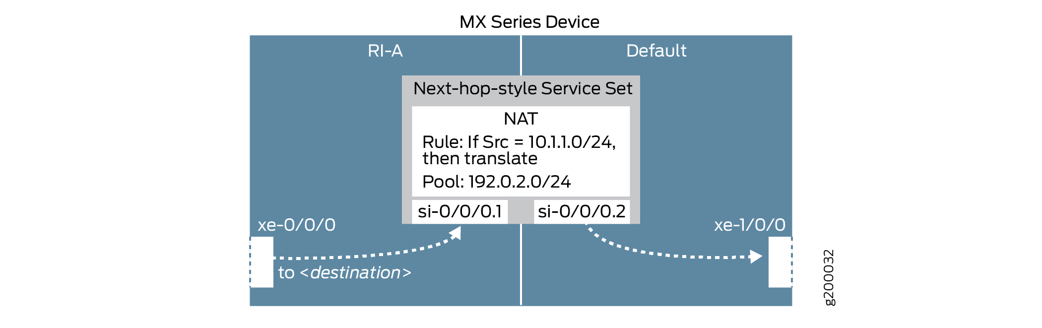
Configuration
To configure inline NAT using a next-hop-style service set, perform these tasks:
- CLI Quick Configuration
- Configure Physical Interfaces
- Enable Inline Services and Create an Inline Interface
- Configure Routing Instance and Identify Traffic to Send Through Inline NAT Service
- Configure NAT Rule and Pool
- Configure the (Next-hop-style) Service Set
CLI Quick Configuration
To quickly configure this example, copy the following commands, paste them into a text file, remove any line breaks, change any details necessary to match your network configuration, and then copy and paste the commands into the CLI at the [edit] hierarchy level.
## Configure interfaces ##
set interfaces xe-0/0/0 unit 0 family inet address 10.1.1.1/24
set interfaces xe-0/0/0 description INSIDE
set interfaces xe-1/0/0 unit 0 family inet address 192.168.1.1/24
set interfaces xe-1/0/0 description OUTSIDE
## Enable inline services, create an si- interface, reserve bandwidth ##
set chassis fpc 0 pic 0 inline-services bandwidth 1g
set interfaces si-0/0/0 unit 1 family inet
set interfaces si-0/0/0 unit 1 service-domain inside
set interfaces si-0/0/0 unit 2 family inet
set interfaces si-0/0/0 unit 2 service-domain outside
## Configure routing instance, feed traffic into the inline NAT service ##
set routing-instances RI-A instance-type virtual-router
set routing-instances RI-A interface xe-0/0/0.0
set routing-instances RI-A interface si-0/0/0.1
set routing-instances RI-A routing-options static route 192.168.1.2/32 next-hop si-0/0/0.1
## Configure a NAT rule and pool ##
set services nat rule SRC-NAT1 match-direction input
set services nat rule SRC-NAT1 term r1 from source-address 10.1.1.0/24
set services nat rule SRC-NAT1 term r1 then translated translation-type basic-nat44
set services nat rule SRC-NAT1 term r1 then translated source-pool p1
set services nat pool p1 address 192.0.2.0/24
## Configure the (next-hop-style) service set ##
set services service-set NH-STYLE-SS-NAT1 nat-rules SRC-NAT1
set services service-set NH-STYLE-SS-NAT1 next-hop-service inside-service-interface si-0/0/0.1
set services service-set NH-STYLE-SS-NAT1 next-hop-service outside-service-interface si-0/0/0.2
Configure Physical Interfaces
Step-by-Step Procedure
Configure the physical interfaces.
[edit interfaces]
user@MX# set xe-0/0/0 unit 0 family inet address 10.1.1.1/24
user@MX# set xe-0/0/0 description INSIDE
user@MX# set xe-1/0/0 unit 0 family inet address 192.168.1.1/24
user@MX# set xe-1/0/0 description OUTSIDE
Enable Inline Services and Create an Inline Interface
Step-by-Step Procedure
Enable inline services for the relevant FPC slot and PIC slot, and define the amount of bandwidth to dedicate for inline services.
The FPC and PIC settings here will create and map to an
si-interface.[edit chassis fpc 0 pic 0] user@MX# set inline-services bandwidth 1g
On the
si-interface, create two logical units. For each unit, specify the protocol family (or families) that will need NAT services, and the ’inside’ or ’outside’ interfaces for the service domain.Note:The FPC and PIC settings here must match the settings defined above.
[edit interfaces si-0/0/0]
user@MX# set unit 1 family inet
user@MX# set unit 1 service-domain inside
user@MX# set unit 2 family inet
user@MX# set unit 2 service-domain outside
Configure Routing Instance and Identify Traffic to Send Through Inline NAT Service
Step-by-Step Procedure
Configure a routing instance that includes the 'ínside' physical and
si-interfaces, as well as a static route that identifies traffic to forward into the inline NAT service through thesi-interface.For simplicity, the static route used here simply identifies server S1.
[edit routing-instances]
user@MX# set RI-A instance-type virtual-router
user@MX# set RI-A interface xe-0/0/0.0
user@MX# set RI-A interface si-0/0/0.1
user@MX# set RI-A routing-options static route 192.168.1.2/32 next-hop si-0/0/0.1
Configure NAT Rule and Pool
Step-by-Step Procedure
Configure a NAT rule that matches on traffic arriving at the MX device from H1’s subnet (10.1.1.0/24), translates it using basic IPv4 NAT, and uses an IP address from pool
p1.[edit services nat] user@MX# set rule SRC-NAT1 match-direction input user@MX# set rule SRC-NAT1 term r1 from source-address 10.1.1.0/24 user@MX# set rule SRC-NAT1 term r1 then translated translation-type basic-nat44 user@MX# set rule SRC-NAT1 term r1 then translated source-pool p1
Configure the NAT pool.
[edit services nat]
user@MX# set pool p1 address 192.0.2.0/24
Configure the (Next-hop-style) Service Set
Step-by-Step Procedure
Configure a service set that uses the inline NAT service (
nat-rules), and the inline interfaces defined above. Use thenext-hop-serviceparameter to specify that this is a next-hop-style service set, and assign thesi-interfaces as ’inside’ and ’outside’ based on their settings above.Traffic will flow into and out of the
si-interfaces to access the inline NAT service.[edit services] user@MX# set service-set NH-STYLE-SS-NAT1 nat-rules SRC-NAT1 user@MX# set service-set NH-STYLE-SS-NAT1 next-hop-service inside-service-interface si-0/0/0.1 user@MX# set service-set NH-STYLE-SS-NAT1 next-hop-service outside-service-interface si-0/0/0.2
Results
chassis {
    fpc 0 {
        pic 0 {
            inline-services {
                bandwidth 1g;
            }
        }
    }
}

services {
    service-set NH-STYLE-SS-NAT1 {
        nat-rules SRC-NAT1;
        next-hop-service {
            inside-service-interface si-0/0/0.1;
            outside-service-interface si-0/0/0.2;
        }
    }
    nat {
        pool p1 {
            address 192.0.2.0/24;
        }
        rule SRC-NAT1 {
            match-direction input;
            term r1 {
                from {
                    source-address {
                        10.1.1.0/24;
                    }
                }
                then {
                    translated {
                        source-pool p1;
                        translation-type {
                            basic-nat44;
                        }
                    }
                }
            }
        }
    }
}

interfaces {
    si-0/0/0 {
       unit 1 {
            family inet;
            service-domain inside;
        }
        unit 2 {
            family inet;
            service-domain outside;
        }
    }
    xe-0/0/0 {
        description INSIDE;
        unit 0 {
            family inet {
                  address 10.1.1.1/24;
            }
        }
    }
    xe-1/0/0 {
        description OUTSIDE;
        unit 0 {
            family inet {
                address 192.168.1.1/24;
            }
        }
    }
}

routing-instances {
    RI-A {
        instance-type virtual-router;
        interface xe-0/0/0.0;
        interface si-0/0/0.1;
        routing-options {
            static {
                route 192.168.1.2/32 next-hop si-0/0/0.1;
            }
        }
    }
}
Verification
Confirm that the configuration is working properly.
Verifying Reachability from Host H1 to Server S1
Purpose
Verify reachability between H1 and S1.
Action
On host H1, verify that the host can ping server S1.
user@H1> ping 192.168.1.2 count 5
PING 192.168.1.2 (192.168.1.2): 56 data bytes
64 bytes from 192.168.1.2: icmp_seq=0 ttl=63 time=0.926 ms
64 bytes from 192.168.1.2: icmp_seq=1 ttl=63 time=0.859 ms
64 bytes from 192.168.1.2: icmp_seq=2 ttl=63 time=0.853 ms
64 bytes from 192.168.1.2: icmp_seq=3 ttl=63 time=0.825 ms
64 bytes from 192.168.1.2: icmp_seq=4 ttl=63 time=0.930 ms

--- 192.168.1.2 ping statistics ---
5 packets transmitted, 5 packets received, 0% packet loss
round-trip min/avg/max/stddev = 0.825/0.879/0.930/0.042 ms
Meaning
H1 can successfully reach S1.
Verifying Address Translation
Purpose
Verify that address translation is working correctly.
Action
On the MX device, verify that the inline NAT configuration details have been applied correctly.
user@MX> show services inline nat pool
Interface: si-0/0/0, Service set: NH-STYLE-SS-NAT1
  NAT pool: p1, Translation type: BASIC NAT44
    Address range: 192.0.2.0-192.0.2.255
    NATed packets: 5, deNATed packets: 5, Errors: 0, Skipped packets: 0
On server S1, verify that the server is receiving the pings from H1’s NAT-translated source IP address (192.0.2.2).
Issue the command below, and send pings again from H1.
Note:For this setup, another MX device is used to represent server S1 to enable monitoring of the inbound traffic.
user@S1> monitor traffic interface xe-1/1/1 no-resolve
verbose output suppressed, use <detail> or <extensive> for full protocol decode
Address resolution is OFF.
Listening on xe-1/1/1, capture size 96 bytes

20:19:36.182690  In IP 192.0.2.2 > 192.168.1.2: ICMP echo request, id 4436, seq 0, length 64
20:19:36.182719 Out IP 192.168.1.2 > 192.0.2.2: ICMP echo reply, id 4436, seq 0, length 64
20:19:37.182918  In IP 192.0.2.2 > 192.168.1.2: ICMP echo request, id 4436, seq 1, length 64
20:19:37.182945 Out IP 192.168.1.2 > 192.0.2.2: ICMP echo reply, id 4436, seq 1, length 64
20:19:38.183914  In IP 192.0.2.2 > 192.168.1.2: ICMP echo request, id 4436, seq 2, length 64
20:19:38.183940 Out IP 192.168.1.2 > 192.0.2.2: ICMP echo reply, id 4436, seq 2, length 64
20:19:39.184872  In IP 192.0.2.2 > 192.168.1.2: ICMP echo request, id 4436, seq 3, length 64
20:19:39.184896 Out IP 192.168.1.2 > 192.0.2.2: ICMP echo reply, id 4436, seq 3, length 64
20:19:40.185882  In IP 192.0.2.2 > 192.168.1.2: ICMP echo request, id 4436, seq 4, length 64
20:19:40.185907 Out IP 192.168.1.2 > 192.0.2.2: ICMP echo reply, id 4436, seq 4, length 64
^C
10 packets received by filter
0 packets dropped by kernel
Meaning
Step 1 above confirms that the inline NAT service parameters and next-hop-style service set are correctly implemented. Step 2 above confirms that server S1 is correctly receiving H1’s pings from its NAT-translated source IP address.
Change History Table
Feature support is determined by the platform and release you are using. Use Feature Explorer to determine if a feature is supported on your platform.
twice-basic-nat-44