Ethernet Automatic Protection Switching Overview
Ethernet automatic protection switching (APS) is a linear protection scheme designed to protect VLAN based Ethernet networks.
With Ethernet APS, a protected domain is configured with two paths, a working path and a protection path. Both working and protection paths can be monitored using an Operations Administration Management (OAM) protocol like Connectivity Fault Management (CFM). Normally, traffic is carried on the working path (that is, the working path is the active path), and the protection path is disabled. If the working path fails, its protection status is marked as degraded (DG) and APS switches the traffic to the protection path, then the protection path becomes the active path.
APS uses two modes of operation, linear 1+1 protection switching architecture and linear 1:1 protection switching architecture. The linear 1+1 protection switching architecture operates with either unidirectional or bidirectional switching. The linear 1:1 protection switching architecture operates with bidirectional switching.
In the linear 1+1 protection switching architecture, the normal traffic is copied and fed to both working and protection paths with a permanent bridge at the source of the protected domain. The traffic on the working and protection transport entities is transmitted simultaneously to the sink of the protected domain, where a selection between the working and protection transport entities is made.
In the linear 1:1 protection switching architecture, the normal traffic is transported on either the working path or on the protection path using a selector bridge at the source of the protection domain. The selector at the sink of the protected domain selects the entity that carries the normal traffic.
Unidirectional and Bidirectional Switching
Unidirectional switching utilizes fully independent selectors at each end of the protected domain. Bidirectional switching attempts to configure the two end points with the same bridge and selector settings, even for a unidirectional failure. Unidirectional switching can protect two unidirectional failures in opposite directions on different entities.
Selective and Merging Selectors
In the linear 1:1 protection switching architecture, where traffic is sent only on the active path, there are two different ways in which the egress direction (the direction out of the protected segment) data forwarding can act: selective selectors and merging selectors. A selective selector forwards only traffic that is received from both the paths regardless of which one is currently active. In other words, with a merging selector the selection of the currently active path only affects the ingress direction. Merging selectors minimize the traffic loss during a protection switch, but they do not guarantee the delivery of the data packets in order.
Revertive and Nonrevertive Switching
For revertive switching, traffic is restored to the working path after the conditions causing the switch have cleared.
For nonrevertive switching, traffic is allowed to remain on the protection path even after the conditions causing the switch have cleared.
The configuration on both the provider edge (PE) routers have to be either in revertive mode or non-revertive mode.
Protection Switching Between VPWS Pseudowires
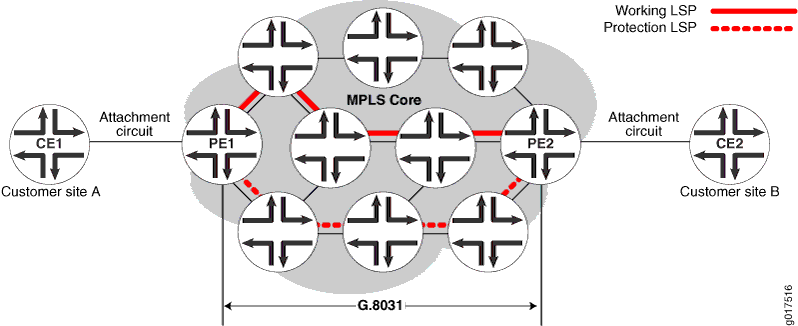
In the scenario diagramed in Figure 1, a Virtual Private Wire Service (VPWS) is provisioned between customer sites A and B using a single pseudowire (layer 2 circuit) in the core network, and two Multiprotocol Label Switching (MPLS) Label Switched Paths (LSPs) are provisioned, one for the working path and the other one for the protection path. CFM CCM will be used to monitor the status of each LSP. Provider edge routers PE1 and PE2 run G.8031 Ethernet APS to select one of the LSPs as the active path. Once the active path is elected at the source end of the protection group, PE1 forwards to traffic from site A to the elected active path. At the sink end of the protection group, PE2 implements a merging selector, meaning it forwards the traffic coming from both the LSPs to the customer site B.
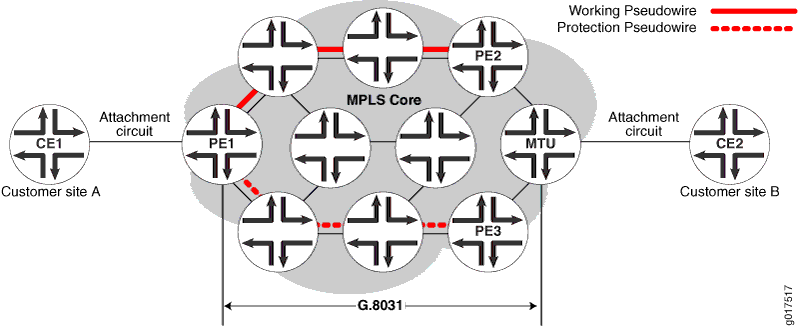
In the scenario represented in Figure 2, a VPWS is provisioned between customer sites A and B using two pseudowires (layer 2 circuit) in the core network, one for the working path and the other for the protection path. CFM CCM will be used to monitor the status of each pseudowire.
Provider edge router PE1 and MTU run G.8031 Ethernet APS to select one of the pseudowires as the active path. Once the active path is elected at the source end of the protection group, PE1 forwards the traffic from site A to the elected active path. At the sink end of the protection group, MTU implements a merging selector, meaning it forwards the traffic coming from both the pseudowires to customer site B.
CLI Configuration Statements
[edit protocols protection-group]
ethernet-aps profile1{
    protocol g8031;
    revert-time seconds;
    hold-time 0-10000ms;
    local-request lockout;
}
revert-time- By default, protection logic restores
the use of the working path once it recovers. The revert-time statement
specifies how much time should elapse before the path for data should
be switched from Protection to Working once recovery for Working has
occurred. A revert-time of zero indicates no reversion. It will default
to 300 sec (5 minutes) if not configured.
hold-time- Once a failure is detected, APS waits
until this timer expires before initiating the protection switch.
The range of the hold-time timer is 0 to 10,000 milliseconds. It will
default to zero if not configured.
local-request- Configuring this value to lockout
or force-switch will trigger lockout or force-switch operation on
the protection groups using this profile.