NAT for GTP
The Network Address Translation (NAT) protocol is used to inspect the GTP traffic between the internal GPRS network and the Internet (external network) and vice versa.
Understanding NAT for GTP
A General Packet Radio Service (GPRS) interface supports both GPRS tunneling protocol (GTP) inspection and Network Address Translation (NAT) simultaneously in the same routing instance. When GTP packets configured with static NAT are inspected in a network, only addresses within IP headers are translated. The addresses within their payloads are not translated. For each endpoint, the related GTP session must belong to the same zone and virtual router. This means the header source IP, C-tunnel IP, and U-tunnel IP in the payload are defined in the same scope for a packet.
When you enable NAT, only the outer IP packet has to be translated. The embedded IP addresses are not translated.
During a GTP packet flow, the source IP address and destination IP address cannot be translated to NAT simultaneously. When you delete or deactivate NAT rule configuration on a device, the NAT rule related GSN and GTP tunnels are deleted. If the NAT rule related GSN number and tunnel number are huge, this deleting process will take several minutes.
Example: Configuring GTP Inspection in NAT
This example shows how to configure a NAT rule to map a private IP (one that is inside the network and not routable) to a public IP (one that is outside of the network and is routable). It also shows how to inspect GTP traffic between an internal and external network.
Requirements
Before you begin, the device must be restarted after GTP is enabled. By default, GTP is disabled on the device.
Overview
In this example, you configure interfaces as ge-0/0/0 and ge-0/0/1, with addresses 10.0.0.254/8 and 123.0.0.254/8. You then configure the security zone and static NAT. You enable the GTP service in the security policies to allow bidirectional traffic between two networks, and you check the traffic between the internal and external network.
Configuration
Procedure
CLI Quick Configuration
To quickly configure this section of the example,
copy the following commands, paste them into a text file, remove any
line breaks, change any details necessary to match your network configuration,
copy and paste the commands into the CLI at the [edit] hierarchy
level, and then enter commit from configuration
mode.
 set interfaces ge-0/0/0 unit 0 family inet address 10.0.0.254/8
set interfaces ge-0/0/1 unit 0 family inet address 123.0.0.254/8
set security zones security-zone zone1 interfaces ge-0/0/0.0 host-inbound-traffic system-services all
set security zones security-zone zone1 host-inbound-traffic protocols all
set security zones security-zone other-zone interfaces ge-0/0/1.0 host-inbound-traffic system-services all
set security zones security-zone other-zone host-inbound-traffic protocols all
set security address-book global address gsn1 10.0.0.1/8
set security address-book global address other-gsn 20.0.0.1/8
set security nat static rule-set rs1 from zone other-zone
set security nat static rule-set rs1 rule r1 match destination-address 123.0.0.1/32
set security nat static rule-set rs1 rule r1 then static-nat prefix 10.0.0.1/32
set security nat proxy-arp interface ge-0/0/0.0 address 123.0.0.1/32
set security gprs gtp profile gtp1
set security gprs gtp profile gtp1 timeout 1
set security gprs gtp profile gtp1 seq-number-validated
set security policies from-zone zone1 to-zone other-zone policy out-gtp match source-address gsn1
set security policies from-zone zone1 to-zone other-zone policy out-gtp match destination-address other-gsn
set security policies from-zone zone1 to-zone other-zone policy out-gtp match application junos-gprs-gtp
set security policies from-zone zone1 to-zone other-zone policy out-gtp then permit application-services gprs-gtp-profile gtp1
set security policies from-zone other-zone to-zone zone1 policy in-gtp match source-address other-gsn
set security policies from-zone other-zone to-zone zone1 policy in-gtp match destination-address gsn1
set security policies from-zone other-zone to-zone zone1 policy in-gtp match application junos-gprs-gtp
set security policies from-zone other-zone to-zone zone1 policy in-gtp then permit application-services gprs-gtp-profile gtp1
Step-by-Step Procedure
To configure GTP inspection in NAT:
Configure interfaces.
[edit]
user@host# set interfaces ge-0/0/0 unit 0 family inet address 10.0.0.254/8
user@host# set interfaces ge-0/0/1 unit 0 family inet address 123.0.0.254/8
Configure and security zones
[edit security]
user@host# set zones security-zone zone1 interfaces ge-0/0/0.0 host-inbound-traffic system-services all
user@host# set zones security-zone zone1 host-inbound-traffic protocols all
user@host# set zones security-zone other-zone interfaces ge-0/0/1.0 host-inbound-traffic system-services all
user@host# set zones security-zone other-zone host-inbound-traffic protocols all
Define the address book.
[edit security]
user@host# set address-book global address gsn1 10.0.0.1/8
user@host# set address-book global address other-gsn 20.0.0.1/8
Define NAT rule.
[edit security nat]
user@host# set static rule-set rs1 from zone other-zone
user@host# set static rule-set rs1 rule r1 match destination-address 123.0.0.1/32
user@host# set static rule-set rs1 rule r1 then static-nat prefix 10.0.0.1/32
user@host# set proxy-arp interface ge-0/0/0.0 address 123.0.0.1/32
Enable GTP profile.
[edit security gprs gtp]
user@host# set profile gtp1
user@host# set profile gtp1 timeout 1
user@host# set profile gtp1 seq-number-validated
Check GTP traffic.
[edit security policies]
user@host# set from-zone zone1 to-zone other-zone policy out-gtp match source-address gsn1
user@host# set from-zone zone1 to-zone other-zone policy out-gtp match destination-address other-gsn
user@host# set from-zone zone1 to-zone other-zone policy out-gtp match application junos-gprs-gtp
user@host# set from-zone zone1 to-zone other-zone policy out-gtp then permit application-services gprs-gtp-profile gtp1
user@host# set from-zone other-zone to-zone zone1 policy in-gtp match source-address other-gsn
user@host# set from-zone other-zone to-zone zone1 policy in-gtp match destination-address gsn1
user@host# set from-zone other-zone to-zone zone1 policy in-gtp match application junos-gprs-gtp
user@host# set from-zone other-zone to-zone zone1 policy in-gtp then permit application-services gprs-gtp-profile gtp1
Results
From configuration mode, confirm your configuration
by entering the show security command. If the output does
not display the intended configuration, repeat the configuration instructions
in this example to correct it.
[edit]
user@host# show security
gprs {
    gtp {
        profile gtp1 {
            timeout 1;
            seq-number-validated;
        }
    }
}
address-book {
    global {
        address gsn1 10.0.0.1/8;
        address other-gsn 20.0.0.1/8;
    }
}
nat {
    static {
        rule-set rs1 {
            from zone other-zone;
            rule r1 {
                match {
                    destination-address 123.0.0.1/32;
                }
                then {
                    static-nat {
                        prefix {
                            10.0.0.1/32;
                        }
                    }
                }
            }
        }
    }
    proxy-arp {
        interface ge-0/0/0.0 {
            address {
                123.0.0.1/32;
            }
        }
    }
}
policies {
    from-zone zone1 to-zone other-zone {
        policy out-gtp {
            match {
                source-address gsn1;
                destination-address other-gsn;
                application junos-gprs-gtp;
            }
            then {
                permit {
                    application-services {
                        gprs-gtp-profile gtp1;
                    }
                }
            }
        }
    }
    from-zone other-zone to-zone zone1 {
        policy in-gtp {
            match {
                source-address other-gsn;
                destination-address gsn1;
                application junos-gprs-gtp;
            }
            then {
                permit {
                    application-services {
                        gprs-gtp-profile gtp1;
                    }
                }
            }
        }
    }
}
zones {
    security-zone trust {
        host-inbound-traffic {
            system-services {
                all;
            }
            protocols {
                all;
            }
        }
        interfaces {
            ge-0/0/0.0;
        }
    }
    security-zone zone1 {
        host-inbound-traffic {
            protocols {
                all;
            }
        }
        interfaces {
            ge-0/0/0.0;
        }
    }
    security-zone other-zone {
        host-inbound-traffic {
            protocols {
                all;
            }
        }
        interfaces {
            ge-0/0/1.0 {
                host-inbound-traffic {
                    system-services {
                        all;
                    }
                }
            }
        }
    }
}
If you are done configuring the device, enter commit from configuration mode.
Understanding Network Address Translation-Protocol Translation
Network Address Translation-Protocol Translation (NAT-PT) is a protocol translation mechanism that can be done in two directions, from IPv4 address format to IPv6 address format and vice versa. NAT-PT binds the addresses in the IPv6 network with addresses in the IPv4 network and vice versa to provide transparent routing for the datagrams traversing between address realms.
In each direction, the static NAT defines a one-to-one mapping from one IP subnet to another IP subnet. The mapping includes a destination IP address translation in one direction and a source IP address translation in the opposite direction.
The main advantage of NAT-PT is that the end devices and networks can run either IPv4 addresses or IPv6 addresses and traffic can be started from any side.
Example: Enhancing Traffic Engineering by Configuring NAT-PT Between an IPv4 and an IPv6 Endpoint with SCTP Multihoming
This example shows how to enhance traffic engineering by configuring NAT-PT between an IPv4 endpoint and an IPv6 endpoint. NAT-PT is a protocol translation mechanism that allows communication between IPv6-only and IPv4-only nodes through protocol-independent translation of IPv4 and IPv6 datagrams, requiring no state information for the session. NAT-PT binds the addresses in the IPv6 network with addresses in the IPv4 network and vice versa to provide transparent routing for the datagrams traversing between address realms. The main advantage of NAT-PT is that the end devices and networks can run either IPv4 addresses or IPv6 addresses and traffic can be started from any side.
Requirements
This example uses the following hardware and software components:
-
SRX Series Firewall
-
Endpoint A connected to an SRX Series Firewall using two IPv6 addresses
-
Endpoint B connected to an SRX Series Firewall using two IPv4 addresses
Overview
In this example, you configure NAT-PT between an IPv4 endpoint and an IPv6 endpoint. Endpoint A is connected to the SRX5400 device using two IPv6 addresses and endpoint B is connected to the SRX5400 device using two IPv4 addresses.
You can configure the SRX5400 device to translate the IP header and IP address list (located in the INIT/INT-ACK message) between an IPv4 address format and an IPv6 address format. In each direction, static NAT defines a one-to-one mapping from one IP subnet to another IP subnet. The mapping includes destination IP address translation in one direction and source IP address translation in the opposite direction.
Figure 1 illustrates the network topology used in this example.
Topology
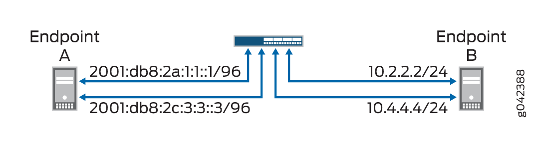
For configuring NAT-PT details between IPv4 and IPv6 endpoints, seeTable 1.
|
Endpoints |
Address One |
Address Two |
|---|---|---|
|
A (IPv6) |
2001:db8:2a:1:1::1/96 |
2001:db8:2c:3:3::3/96 |
|
B (IPv4) |
10.2.2.2/24 |
10.4.4.4/34 |
Configuration
CLI Quick Configuration
To quickly configure this example, copy the following commands, paste them into a
text file, remove any line breaks, change any details necessary to match your
network configuration, copy and paste the commands into the CLI at the
[edit] hierarchy level, and then enter
commit from configuration mode.
               set interfaces ge-4/0/0 unit 0 family inet address 10.1.1.100/24


               set interfaces ge-4/0/0 unit 0 family inet6 address 2001:db8:2a:1:1::100/96


               set interfaces ge-4/0/1 unit 0 family inet address 10.2.2.100/24


               set interfaces ge-4/0/1 unit 0 family inet6 address 2001:db8:2b:2:2::100/96


               set interfaces ge-4/0/2 unit 0 family inet address 10.3.3.100/24


               set interfaces ge-4/0/2 unit 0 family inet6 address 2001:db8:2c:3:3::100/96


               set interfaces ge-4/0/3 unit 0 family inet address 10.4.4.100/24


               set interfaces ge-4/0/3 unit 0 family inet6 address 2001:db8:2d:4:4::100/96


               set security zones security-zone sctp_zone1 host-inbound-traffic system-services all


               set security zones security-zone sctp_zone1 host-inbound-traffic protocols all


               set security zones security-zone sctp_zone1 interfaces ge-4/0/0.0


               set security zones security-zone sctp_zone1 interfaces ge-4/0/2.0


               set security zones security-zone sctp_zone2 host-inbound-traffic system-services all


               set security zones security-zone sctp_zone2 host-inbound-traffic protocols all


               set security zones security-zone sctp_zone2 interfaces ge-4/0/1.0


               set security zones security-zone sctp_zone2 interfaces ge-4/0/3.0


               set security nat static rule-set sctp-natpt-from-zone1 from zone sctp_zone1


               set security nat static rule-set sctp-natpt-from-zone1 rule r1-dst match destination-address 2001:db8:2b:2:2::2/96


               set security nat static rule-set sctp-natpt-from-zone1 rule r1-dst then static-nat prefix 10.2.2.2/32


               set security nat static rule-set sctp-natpt-from-zone1 rule r3-dst match destination-address 2001:db8:2d:4:4::4/96


               set security nat static rule-set sctp-natpt-from-zone1 rule r3-dst then static-nat prefix 10.4.4.4/32


               set security nat static rule-set sctp-natpt-from-zone2 from zone sctp_zone2


               set security nat static rule-set sctp-natpt-from-zone2 rule r2-dst match destination-address 10.1.1.1/32


               set security nat static rule-set sctp-natpt-from-zone2 rule r2-dst then static-nat prefix 2001:db8:2a:1:1::1/96


               set security nat static rule-set sctp-natpt-from-zone2 rule r4-dst match destination-address 10.3.3.3/32


               set security nat static rule-set sctp-natpt-from-zone2 rule r4-dst then static-nat prefix 2001:db8:2c:3:3::3/96
Procedure
Step-by-Step Procedure
To configure NAT-PT between an IPv4 endpoint and an IPv6 endpoint:
-
Configure interfaces.
[edit interfaces] user@host# set ge-4/0/0 unit 0 family inet address 10.1.1.100/24 user@host# set ge-4/0/0 unit 0 family inet6 address 2001:db8:2a:1:1::100/96 user@host# set ge-4/0/1 unit 0 family inet address 10.2.2.100/24 user@host# set ge-4/0/1 unit 0 family inet6 address 2001:db8:2b:2:2::100/96 user@host# set ge-4/0/2 unit 0 family inet address 10.3.3.100/24 user@host# set ge-4/0/2 unit 0 family inet6 address 2001:db8:2c:3:3::100/96 user@host# set ge-4/0/3 unit 0 family inet address 10.4.4.100/24 user@host# set ge-4/0/3 unit 0 family inet6 address 2001:db8:2d:4:4::100/96 -
Configure zones.
[edit security zones] user@host# set security-zone sctp_zone1 host-inbound-traffic system-services all user@host# set security-zone sctp_zone1 host-inbound-traffic protocols all user@host# set security-zone sctp_zone1 interfaces ge-4/0/0.0 user@host# set security-zone sctp_zone1 interfaces ge-4/0/2.0 user@host# set security-zone sctp_zone2 host-inbound-traffic system-services all user@host# set security-zone sctp_zone2 host-inbound-traffic protocols all user@host# set security-zone sctp_zone2 interfaces ge-4/0/1.0 user@host# set security-zone sctp_zone2 interfaces ge-4/0/3.0 -
Configure rules for the first static NAT zone.
[edit security nat] user@host# set static rule-set sctp-natpt-from-zone1 from zone sctp_zone1 -
Specify the static NAT rule match criteria for the traffic coming from zone 1.
[edit security nat] user@host# set static rule-set sctp-natpt-from-zone1 rule r1-dst match destination-address 2001:db8:2b:2:2::2/128 user@host# set static rule-set sctp-natpt-from-zone1 rule r1-dst then static-nat prefix 10.2.2.2/32 user@host# set static rule-set sctp-natpt-from-zone1 rule r3-dst match destination-address 2001:db8:2d:4:4::4/128 user@host# set static rule-set sctp-natpt-from-zone1 rule r3-dst then static-nat prefix 10.4.4.4/32 -
Configure rules for the second static NAT zone.
[edit security nat] user@host# set static rule-set sctp-natpt-from-zone2 from zone sctp_zone2 -
Specify the static NAT rule match criteria for the traffic coming from zone 2.
[edit security nat]
user@host# set static rule-set sctp-natpt-from-zone2 rule r2-dst match destination-address 10.1.1.1/32
user@host# set static rule-set sctp-natpt-from-zone2 rule r2-dst then static-nat prefix 2001:db8:2a:1:1::1/128
user@host# set static rule-set sctp-natpt-from-zone2 rule r4-dst match destination-address 10.3.3.3/32
user@host# set static rule-set sctp-natpt-from-zone2 rule r4-dst then static-nat prefix 2001:db8:2a:3:3::3/128
Results
From configuration mode, confirm your configuration by entering the
show interfaces, show security zones,
and show security nat static commands. If the output does
not display the intended configuration, repeat the configuration
instructions in this example to correct it.
[edit]
    user@host# show interfaces
    ge-4/0/0 {
    unit 0 {
        family inet {
            address 10.1.1.100/24;
        }
        family inet6 {
            address 2001:db8:2a:1:1::100/96;
        }
    }
}
ge-4/0/1 {
    unit 0 {
        family inet {
            address 10.2.2.100/24;
        }
        family inet6 {
            address 2001:db8:2b:2:2::100/96;
        }
    }
}
ge-4/0/2 {
    unit 0 {
        family inet {
            address 10.3.3.100/24;
        }
        family inet6 {
            address 2001:db8:2c:3:3::100/96;
        }
    }
}
ge-4/0/3 {
    unit 0 {
        family inet {
            address 10.4.4.100/24;
        }
        family inet6 {
            address 2001:db8:2d:4:4::100/96;
        }
    }
}
[edit]
user@host# show security zones
security-zone sctp_zone1 {
    host-inbound-traffic {
        system-services {
            all;
        }
        protocols {
            all;
        }
    }
    interfaces {
        ge-4/0/0.0;
        ge-4/0/2.0;
    }
}
security-zone sctp_zone2 {
    host-inbound-traffic {
        system-services {
            all;
        }
        protocols {
            all;
        }
    }
    interfaces {
        ge-4/0/1.0;
        ge-4/0/3.0;
    }
}
[edit]
user@host# show security nat static
rule-set sctp-natpt-from-zone1 {
    from zone sctp_zone1;
    rule r1-dst {
        match {
            destination-address 2001:db8:2b:2:2::2/128;
        }
        then {
            static-nat {
                prefix {
                    10.2.2.2/32;
                }
            }
        }
    }
    rule r3-dst {
        match {
            destination-address 2001:db8:2d:4:4::4/128;
        }
        then {
            static-nat {
                prefix {
                    10.4.4.4/32;
                }
            }
        }
    }
}
rule-set sctp-natpt-from-zone2 {
    from zone sctp_zone2;
    rule r2-dst {
        match {
            destination-address 10.1.1.1/32;
        }
        then {
            static-nat {
                prefix {
                    2001:db8:2a:1:1::1/128;
                }
            }
        }
    }
    rule r4-dst {
        match {
            destination-address 10.3.3.3/32;
        }
        then {
            static-nat {
                prefix {
                    2001:db8:2c:3:3::3/128;
                }
            }
        }
    }
}
If you are done configuring the device, enter commit from
configuration mode.
Verification
Verifying the Configuration
Purpose
Verify that the NAT-PT configuration between an IPv4 endpoint and an IPv6 endpoint is correct.
Action
From operational mode, enter the show security zones and
show security nat static rule all commands.
user@host> show security zones

Security zone: sctp_zone1
  Send reset for non-SYN session TCP packets: Off
  Policy configurable: Yes
  Interfaces bound: 2
  Interfaces:
    ge-4/0/0.0
    ge-4/0/2.0

Security zone: sctp_zone2
  Send reset for non-SYN session TCP packets: Off
  Policy configurable: Yes
  Interfaces bound: 2
  Interfaces:
    ge-4/0/1.0
    ge-4/0/3.0
user@host> show  security nat static rule all
Total static-nat rules: 4
Total referenced IPv4/IPv6 ip-prefixes: 4/4

Static NAT rule: r1-dst               Rule-set: sctp-natpt-from-zone1
  Rule-Id                    : 1
  Rule position              : 1
  From zone                  : sctp_zone1
  Destination addresses      : 2001:db8:2b:2:2::2
  Host addresses             : 10.2.2.2
  Netmask                    : 128
  Host routing-instance      : N/A
  Translation hits           : 0
    Successful sessions      : 0
    Failed sessions          : 0
  Number of sessions         : 0

Static NAT rule: r3-dst               Rule-set: sctp-natpt-from-zone1
  Rule-Id                    : 2
  Rule position              : 2
  From zone                  : sctp_zone1
  Destination addresses      : 2001:db8:2d:4:4::4
  Host addresses             : 10.4.4.4
  Netmask                    : 128
  Host routing-instance      : N/A
  Translation hits           : 0
    Successful sessions      : 0
    Failed sessions          : 0
  Number of sessions         : 0

Static NAT rule: r2-dst               Rule-set: sctp-natpt-from-zone2
  Rule-Id                    : 3
  Rule position              : 3
  From zone                  : sctp_zone2
  Destination addresses      : 10.1.1.1
  Host addresses             : 2001:db8:2a:1:1::1
  Netmask                    : 32
  Host routing-instance      : N/A
  Translation hits           : 0
    Successful sessions      : 0
    Failed sessions          : 0
  Number of sessions         : 0

Static NAT rule: r4-dst               Rule-set: sctp-natpt-from-zone2
  Rule-Id                    : 4
  Rule position              : 4
  From zone                  : sctp_zone2
  Destination addresses      : 10.3.3.3
  Host addresses             : 2001:db8:2c:3:3::3
  Netmask                    : 32
  Host routing-instance      : N/A
  Translation hits           : 0
    Successful sessions      : 0
    Failed sessions          : 0
  Number of sessions         : 0
Meaning
The show security zones command displays all the zones
configured and the interfaces associated with the zone. The show
security nat static rule all command displays all the static
NAT rules configured.