
Overview and TEID-Based Session Distribution and Asymmetric Fat Tunnel Processing
Learn how Power-Mode IPsec (PMI) flow-based CoS enables high-performance GTP-U traffic handling using TEID-based hash distribution, IPsec session affinity, and asymmetric fat tunnel processing to distribute GTP sessions across multiple cores on SRX Series Firewalls.
PMI is a new mode of operation that provides IPsec performance improvements.
PMI Flow-Based CoS Functions for GTP-U
With non-GTP traffic, the per-flow class of service (CoS) solution assumes that all the packets of the same session should have same Differentiated Services code point (DSCP) value. The assumption does not work for GPRS tunneling protocol, user plane (GTP-U) because it carries different user data. Therefore, there will be different DSCP code points for the same 5-tuple GTP session. If you combine the GTP-U session distribution solution with per-flow CoS solution, you can provide a per-flow CoS solution for GTP-U scenario. Even if it carries multiple streams with a different DSCP code inside one GTP tunnel.
The following information gives an overview on tunnel endpoint identifier (TEID)-based hash distributions and asymmetric fat tunnel solution.
TEID-based hash distributions: GTP-U uses a fixed UDP port-2152 as its source port and destination port. There might be data streams from different users multiplexed within a single flow session, so 5-tuple is not enough to separate these data streams. There is a 4-byte field inside GTP payload called TEID, which is used to identify different connections in the same GTP tunnel. In order to migrate the GTP sessions to the anchor PIC, you need IPsec session affinity. Hence, a 6-tuple (including TEID) hash distribution is introduced for creating GTP-U sessions to different cores on anchor PIC, instead of creating GTP-U sessions only on the Anchor PIC.
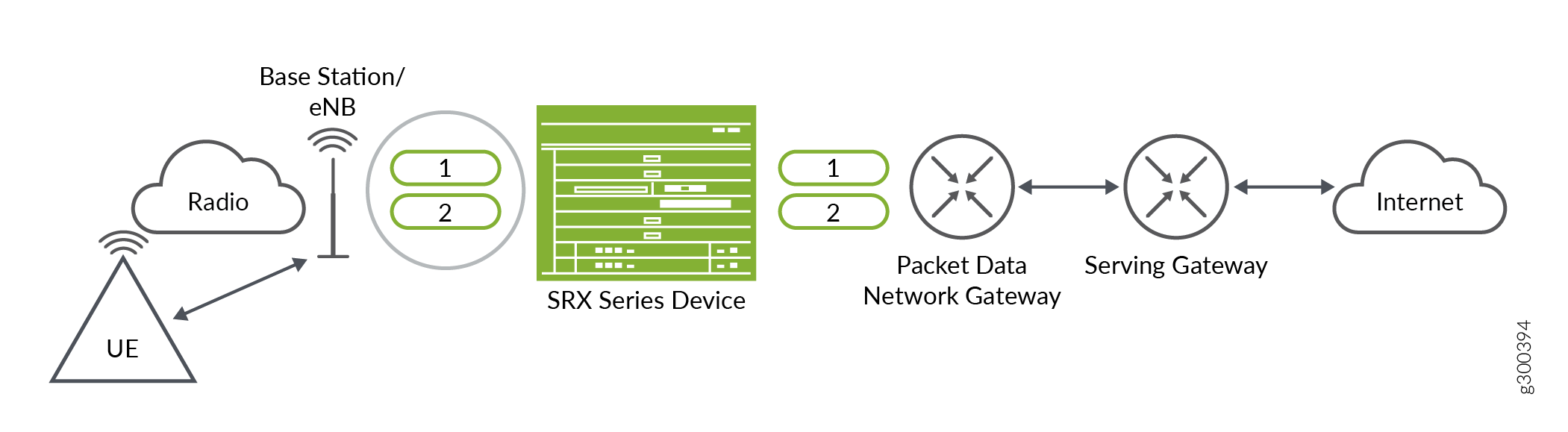
The Figure 1 shows a typical LTE network architecture where an SRX Series Firewall is deployed as security gateway. A fat GTP tunnel carries data from different users. IPsec tunnels on the security gateway could be a fat tunnel due to the fat GTP tunnel. The SRX Series Firewall can create one GTP session with a high-bandwidth of GTP traffic. However, the throughput is limited to one core processor's performance.
If you use TEID-based hash distribution for creating GTP-U sessions when PowerMode IPsec (PMI) and IPsec session affinity are enabled, following events take place.
You can enable a firewall to process asymmetric fat tunnels (For example: 30Gbps on encryption direction/3 Gbps on decryption direction) because PMI provides parallel encryption on multiple cores for one tunnel.
You can split a fat GTP session to multiple sessions and distribute it to different cores. This helps to increase the bandwidth for fat GTP tunnel on the firewalls.
Asymmetric fat tunnel solution: An SRX Series Firewalls support asymmetric fat tunnels because PMI provides parallel encryption on multiple cores for one tunnel. The TEID-based hash distribution is introduced for creating GTP-U sessions to multiple cores on anchor PIC. When both PMI and IPsec session affinity are enabled, the clear-txt traffic acts as a fat GTP tunnel. This helps a fat GTP session to split into multiple slim GTP sessions and handle it on multiple cores simultaneously.
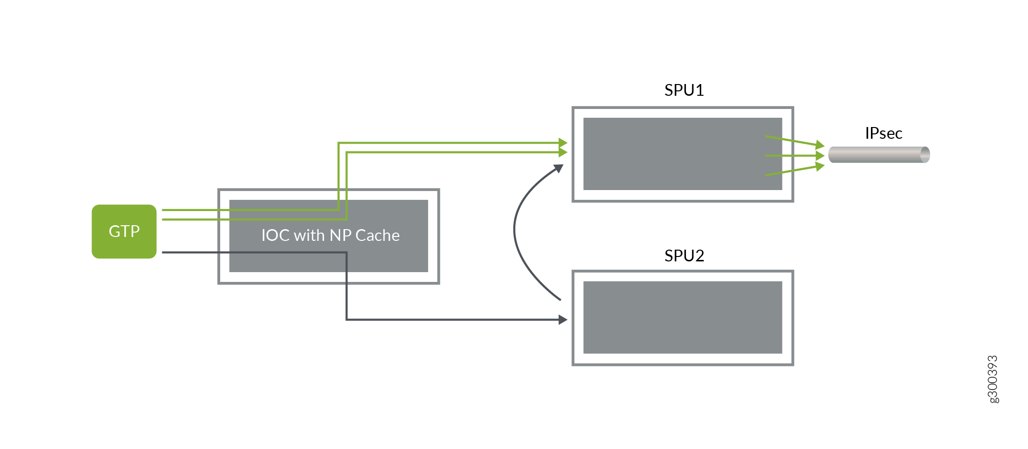
The Figure 2 shows how a fat tunnel processed when TEID-based hash distribution for creating GTP-U sessions.
On the encryption path, when one GTP tunnel with the 5-tuple enters, the Input/Output card (IOC) distributes the traffic into different cores according to 6-tuple including TEID hash. If the traffic is destined for the same IPsec tunnel, flow creates multiple GTP sessions on different cores of the anchor Security Processing Units (SPU).
The flow installs multiple NP caches on the IOC and when subsequent packets hit the NP cache and are distributed to different cores on the anchor SPU.
Configuration to Enable PMI and GTP
The following configuration helps to enable PMI and GTP.
Before you begin determine the following:
Understand how PMI and GTP sessions are established.
Per‑flow CoS functions for GTP‑U traffic are available in PMI mode.
TEID‑based hash distribution for creating GTP‑U sessions multiple cores on the anchor PIC when both PMI and IPsec session affinity are enable.
TEID‑based hash distribution helps split a large GTP session into multiple smaller GTP sessions that can be processed in parallel on multiple cores.
With this enhancement, per‑flow CoS for GTP‑U traffic is enabled even when the traffic carries multiple streams with different DSCP codes within one GTP tunnel.
The following steps explain how to enable PMI and GTP sessions.