Understanding Junos Fusion Ports
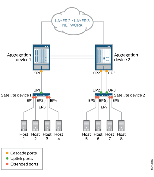
In a Junos Fusion topology, cascade, uplink, and extended ports are components that play key roles. Figure 1 shows a sample Junos Fusion topology, which serves as a point of reference for this discussion of cascade, uplink, and extended ports.
In the Junos Fusion topology shown in Figure 1, two aggregation devices and two satellite devices are deployed. The aggregation devices are connected to each other through a multichassis link aggregation group (MC-LAG). Each satellite device has a single-homed connection to its respective aggregation device through one or two links.
On the aggregation devices in each illustration, each link is connected to a cascade port (for example, CP1 on Aggregation device 1), while on the satellite devices, each link is connected to an uplink port (for example, UP1 on Satellite device 1). Hosts 1 through 4 are connected to Satellite device 1 through extended ports EP1 through EP4, and so on.

This topic provides the following information:
Understanding Cascade Ports
A cascade port is a physical interface on an aggregation device that provides a connection to a satellite device. A cascade port on an aggregation device connects to an uplink port on a satellite device.
On an aggregation device, you can set up one or more cascade port connections with a satellite device. For example, in the Junos Fusion topology shown in Figure 1, Aggregation device 1 has one cascade port connection (CP1) to Satellite device 1, and Aggregation device 2 has two cascade port connections (CP2 and CP3) to Satellite device 2.
When there are multiple cascade port connections to a satellite
device, as shown in Figure 1, the traffic handled by the ports is automatically load-balanced.
For a packet destined for a satellite device, the cascade port over
which to forward the packet is chosen based on a per-packet hash that
is computed using key fields in the packet. To select the key fields
to be used, you can specify the hash-key statement in the [edit forwarding-options] hierarchy or the enhanced-hash-key statement in the [edit forwarding-options], [edit
logical-systems logical-system-name routing-instances instance-name forwarding-options], and [edit
routing-instances instance-name forwarding-options] hierarchies.
The 802.1BR tag is not included in the load-balancing hash computation for cascade ports.
In addition, a cascade port can handle the traffic for all extended ports on a particular satellite device. However, you cannot specify that a particular cascade port handle the traffic for a particular extended port.
After you configure an interface as a cascade port (for example,
by issuing set interfaces xe-0/0/1 cascade-port), you cannot
configure the interface as a Layer 2 interface (for example, by issuing set interfaces xe-0/0/1 unit 0 family bridge) or a Layer 3
interface (for example, set interfaces xe-0/0/1 unit 0 family
inet). If you try to configure a cascade port as a Layer 2 or
Layer 3 interface, you receive an error message.
On a cascade port, you can configure class-of-service (CoS) policies.
Understanding Uplink Ports
An uplink port is a physical interface on a satellite device that provides a connection to an aggregation device. An uplink port on a satellite device connects to a cascade port on an aggregation device.
After a cascade port is configured on the aggregation device end of a link, a corresponding uplink port is automatically created on the satellite device. From the aggregation device, you can monitor port and queue statistics for uplink ports. However, we do not recommend that you configure Layer 2 or Layer 3 forwarding features on uplink ports.
On a satellite device, you can set up one or more uplink port connections to an aggregation device. For example, in the Junos Fusion topology shown in Figure 1, Satellite device 1 has one uplink port (UP1) to Aggregation device 1, and Satellite device 2 has two uplink ports (UP2 and UP3) to Aggregation device 2.
When a satellite device has multiple uplink ports to an aggregation device, the traffic from the extended ports is automatically load-balanced among the uplink ports. For example, in the Junos Fusion topology shown in Figure 1, the traffic from extended ports EP5 through EP8 is load balanced between uplink ports UP2 and UP3 to reach Aggregation device 2. In this situation, each packet is examined, and if an IPv4 or IPv6 header is found, a load-balancing algorithm chooses the uplink port based on the header (source and destination IP addresses, and source and destination TCP/UDP ports). If an IPv4 or IPv6 header is not found, the load-balancing algorithm chooses the uplink port based on the Layer 2 header (destination and source MAC addresses, Ethertype, and outer VLAN ID) of the packet.
Understanding Extended Ports
An extended port is a physical interface on a satellite device that provides a connection to servers or endpoints. To an aggregation device, a satellite device appears as an additional Flexible PIC Concentrator (FPC) and the extended ports on the satellite device appear as additional interfaces to be managed by the aggregation device.
On aggregation devices, you can configure extended ports by using the same Junos OS CLI and naming convention used for Junos OS interfaces on standalone routers and switches. When configuring an extended port, the FPC slot number must be in the range of 65 through 254. This applies to all currently supported versions of Junos OS.
For example, for the four extended ports shown on Satellite device 1 in Figure 1, the FPC slot number could be 100, the PIC slot number could be 0, the first extended port could be 1, the second extended port could be 2, the third extended port could be 3, and the fourth extended port could be 4. The complete 10-Gigabit Ethernet extended port names could be as follows:
xe-100/0/1
xe-100/0/2
xe-100/0/3
xe-100/0/4
You can configure the following features on extended ports:
Layer 2 bridging protocols
Integrated routing and bridging (IRB)
Firewall filters
CoS policies
