Monitoring X2 Traffic
This topic covers X2 traffic monitoring on SRX Series Firewalls.
Understanding X2 Traffic Monitoring
In an LTE mobile network, SRX Series Firewalls act as secure gateways connecting Evolved Node Bs (eNodeBs) for signal handover, monitoring, and radio coverage. SRX Series Firewalls use IPsec tunnels to connect eNodeBs. The user plane and control plane traffic that flows from one eNodeB to the other eNodeB is called the X2 traffic.
X2 Traffic Monitoring Overview
The X2 traffic passing through IPsec tunnels is encrypted. Because of this, mobile network operators need a way to monitor X2 traffic so that they can debug handover issues across eNodeBs. The Junos OS implementation allows monitoring of the X2 traffic by snooping into the cleartext X2 traffic as it flows through the SRX Series Firewall coming out of one IPsec tunnel and going into the other IPsec tunnel—after traffic is decrypted and before it is encrypted again.
Figure 1 shows the flow of X2 traffic within the SRX Series Firewall. As the traffic reaches the SRX Series Firewall on one st0.x interface, it gets decrypted. Then it is encrypted and forwarded to the destination eNodeB through its dedicated st0.y interface. Snooping is performed on the decrypted X2 traffic on the SRX Series Firewall.
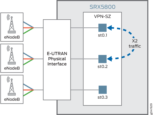
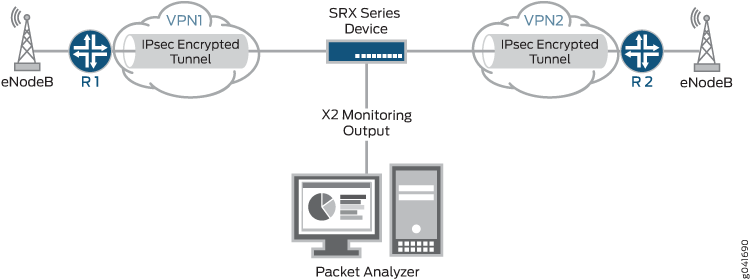
Figure 2 shows a mobile operators network with an SRX Series Firewall providing IPsec tunnel connection between the two eNodeBs. The SRX Series Firewall is connected to a packet analyzer (also called a sniffing device) that is used for collecting and monitoring the X2 traffic. The IPsec tunnel from each eNodeB terminates on a dedicated secure tunnel interface on the SRX Series Firewall. Inbound traffic coming out of the IPsec tunnel is decrypted while outbound traffic leaving the device is encrypted.
To monitor the X2 traffic, you can configure up to 15 different mirror filters that specify unique sets of parameters against which traffic is matched. The filtered packets are duplicated and sent to a physical interface. To allow the packet analyzer to capture the filtered packets, you specify the output interface on the SRX Series Firewall and the MAC address of the packet analyzer. Because the output interface is connected to the same Layer 2 network as the packet analyzer, once mirror filtering is turned on, the packet analyzer can collect and analyze the X2 traffic.
The SRX Series mirror filter feature is bidirectional, much like a session. X2 traffic flowing through an IPSec VPN that matches a mirror filter is mirrored and analyzed; traffic returning from those devices is also mirrored and analyzed.
Starting in Junos OS Release 18.4R1, if the output X2 interface of a mirror filter is configured for an st0 interface to filter traffic that you want to analyze, the packet is duplicated and encrypted by the IPsec tunnel bound to the st0 interface. This enhancement supports the SRX Series Firewalls to send traffic mirrored from a port on an IPsec tunnel. Mirrored traffic includes unmodified Layer 3 headers.
Although there is no minimum required number of parameters for a mirror filter, please be mindful that if you specify too few criteria or accidentally commit an incomplete filter, an over-proportional amount of traffic flow through the system could be mirrored.
Limitations of X2 Traffic Monitoring
-
For X2 traffic in a chassis cluster setup, mirrored packets cannot traverse through the data link (fabric interface).
-
Support for X2 traffic mirroring is not available with PowerMode IPsec (PMI) enabled. If PMI is enabled in one direction but disabled in the other, you can capture X2 traffic mirroring only for the direction where PMI is not active.
X2 Traffic Terminology
Table 1 lists some X2 traffic related terms and their descriptions.
|
Term |
Description |
|---|---|
|
Evolved packet core (EPC) |
Main component of System Architecture Evolution (SAE) and is also known as the SAE core. The EPC supports the IP network and serves as the equivalent of a General Packet Radio Service (GPRS) network, using the mobility management entity (MME), Serving Gateway (SGW), and Packet Data Network Gateway (PGW) subcomponents. |
|
Evolved Universal Terrestrial Radio Access Network (E-UTRAN) |
A radio access network standard. E-UTRAN is a new air interface system. It provides higher data rates and lower latency and is optimized for packet data. It uses Orthogonal Frequency-Division Multiple Access (OFDMA) for the downlink and Single-carrier Frequency Division Multiple Access for the uplink. |
|
Evolved Node B (eNodeB) |
A device connected to the mobile phone network that communicates directly with mobile handsets, like a base transceiver station in Global System for Mobile Communications (GSM) networks. An eNodeB is controlled by a radio network controller (RNC). |
|
Long Term Evolution (LTE) |
A standard for wireless communication of high-speed data for mobile phones and data terminals. It increases the capacity and speed using a different radio interface and makes core network improvements. |
|
X2 interface |
A point-to-point logical interface between two eNodeBs with the E-UTRAN. It supports the exchange of signaling information between two eNodeBs and supports the forwarding of protocol data units (PDUs) to the respective tunnel endpoints. |
|
X2 Application Protocol (X2AP) |
Protocol used by the X2 interface. It is used for handling the user equipment mobility within the E-UTRAN and provides the following functions:
|
Example: Configuring a Mirror Filter for X2 Traffic Monitoring
This example shows how to configure a mirror filter to monitor X2 traffic between two eNodeBs in an LTE mobile network.
Requirements
Before you begin:
-
Understand X2 traffic monitoring. .
-
Configure the interfaces, security zones, security policies, and the route-based VPN tunnels to allow data to be securely transferred between the SRX Series Firewall and the two eNodeBs.
Overview
As a network operator, you need a way to monitor the X2 traffic to debug any handover issues across eNodeBs. The mirror filter feature allows you to do that. Traffic coming out of an IPsec tunnel is decrypted, mirrored and analyzed, and then encrypted again to go into the outbound IPsec tunnel.
More specifically, traffic that matches a mirror filter is mirrored and sent to an output interface that is connected to a packet analyzer (also called a sniffing device). The packet analyzer analyzes the X2 traffic, allowing you to monitor it. Then the traffic is encrypted again before it is sent to the outbound IPsec tunnel.
The SRX Series mirror filter feature is bidirectional, much like a session. X2 traffic flowing through an IPSec VPN that matches a mirror filter is mirrored and analyzed; traffic returning from those devices is also mirrored and analyzed.
To use the mirror filter feature to monitor X2 traffic, you configure mirror filters. You can configure up to 15 different mirror filters to be used concurrently to filter for various kinds of traffic. Each mirror filter contains a set of parameters and their values against which traffic is matched.
Although there is no minimum required number of parameters for a mirror filter, please be mindful that if you specify too few criteria or accidentally commit an incomplete filter, an over-proportional amount of traffic flow through the system could be mirrored.
A mirror filter can contain some or all of the following parameters to filter traffic:
-
destination IP address prefix
-
destination port
-
IP protocol
-
source IP address prefix
-
source port
-
incoming and outgoing interfaces
You also specify the output interface and the MAC address of the packet analyzer as part of the configuration.
In this example, an SRX Series Firewall uses IPsec tunnels to connect two eNodeBs in an LTE mobile network. The example configures a mirror filter called traffic-https.
Figure 3 shows the SRX Series Firewall connecting to the eNodeBs using IPsec tunnels. The SRX Series Firewall is also connected to a packet analyzer.
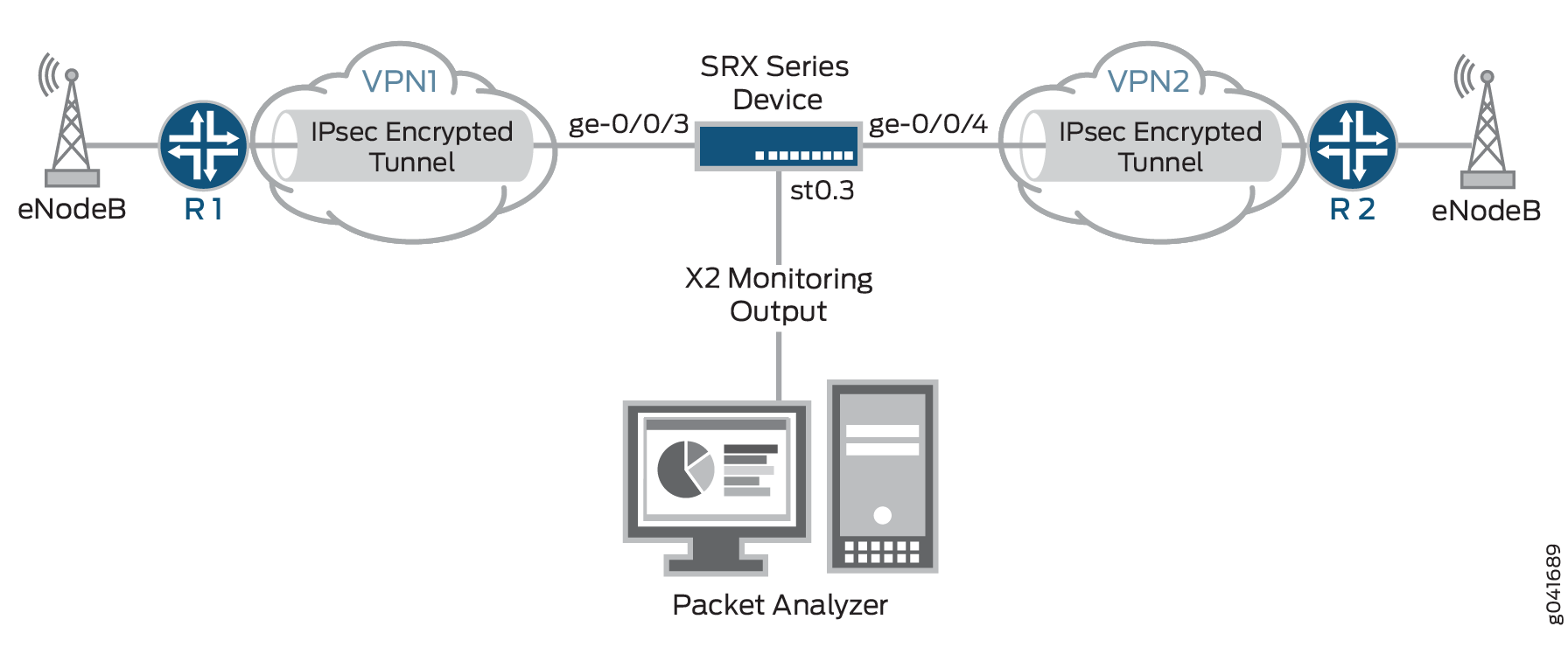
In this example, all HTTPS traffic is analyzed whose destination is to devices with IP addresses that have the prefix 203.0.113.0/24 and for which the destination port 443 is used, the default port for HTTPS traffic. Packets that match the traffic-https filter are mirrored and sent through the output interface ge-0/0/5 to the packet analyzer with the MAC address 00:50:56:87:20:5E. Returning traffic from these devices is also monitored.
The output interface for mirror filter is that of the packet analyzer, which is why the HTTP protocol is used.
The output interface for the packet analyzer uses the HTTP protocol.
Configuration
Procedure
CLI Quick Configuration
To quickly configure this example, copy the
following commands, paste them into a text file, remove any line breaks,
change any details necessary to match your network configuration,
copy and paste the commands into the CLI at the [edit] hierarchy
level, and then enter commit from configuration mode.
set security forwarding-options mirror-filter traffic-https
set security forwarding-options mirror-filter traffic-https destination-port 443
set security forwarding-options mirror-filter traffic-https destination-prefix 203.0.113.0/24
set security forwarding-options mirror-filter traffic-https protocol 6
set security forwarding-options mirror-filter traffic-http output interface ge-0/0/5
set security forwarding-options mirror-filter traffic-http output destination-mac 00:50:56:87:20:5E
Step-by-Step Procedure
The following example requires you to navigate various levels in the configuration hierarchy. For instructions on how to do that, see Using the CLI Editor in Configuration Mode in the CLI User Guide.
To configure a mirror filter for monitoring X2 traffic:
-
Create a mirror filter called traffic-https.
[edit]
user@host# edit security forwarding-options mirror-filter traffic-https
-
Specify the mirror filter parameters against which traffic is matched.
[edit security forwarding-options mirror-filter traffic-https]
user@host# set destination-port 443
user@host# set destination-prefix 203.0.113.0/24
user@host# set protocol 6
-
Specify the output interface for the mirrored packets to be sent to the packet analyzer.
[edit security forwarding-options mirror-filter traffic-https]
user@host# set output interface ge-0/0/5
-
Specify the MAC address of the packet analyzer as a destination for all mirrored packets, that is, those packets that match the mirror filters.
[edit security forwarding-options mirror-filter traffic-https]
user@host# set output destination-mac 00:50:56:87:20:5E
Results
From configuration mode, confirm your configuration
by entering the show security forwarding-options command.
If the output does not display the intended configuration, repeat
the configuration instructions in this example to correct it.
user@host# show security forwarding-options
    mirror-filter traffic-https {
        protocol 6;
        destination-port 443;
        destination-prefix 203.0.113.0/24;
        output {
            interface ge-0/0/5;
            destination-mac 00:50:56:87:20:5E;
        }
    }
If you are done configuring the device, enter commit from configuration mode.
Verification
Confirm that the configuration is working properly.
Verifying the Status of Mirror Filter
Purpose
Verify that mirror filter is active or not.
Action
From operational mode, enter the show security
forward-options mirror-filter command for the specific mirror
filter.
user@host> show security forward-options mirror-filter traffic-https
Security mirror status

    mirror-filter-name: traffic-https
    protocol: 6
		 destination-port: 443
    destination-prefix 203.0.113.0/24
    filter-counters: 2
    output-counters: 2
Meaning
The output provides the mirror filter status. It shows that a mirror filter called traffic-https is active. The traffic-https mirror filter specifies the protocol, destination prefix, and destination port that traffic must match in order for it to be mirrored and analyzed.
This output shows that two packets were mirrored.