Reverse Route Packet Mode using Virtual Router
During flow processing, when the traffic route
between the server and client is changed, the traffic reroutes using
the virtual router (VR). The VR used in rerouting is available in
the interface or the filter-based forwarding (FBF). The behavior of
the reroute is monitored using the set security flow advanced-options
reverse-route-packet-mode-vr command.
The reverse-route-packet-mode-vr command works
on root logical system and is enabled globally.
When the reverse route option is enabled, there is no change in the packet flow. When the reverse route option is disabled, the route lookup uses the VR from the packet incoming interface. If the VR in the route is incorrectly configured, then the traffic between the server and client is dropped.
The resolve reserve route in the flow first path is not configured as the VR information from the client to the server packet is not available.
For example, Figure 1 shows the behavior of the packet flow when the reverse-route-packet-mode-vr command is not configured. The client to server traffic uses the
routing instance VR2 of incoming interface ge-0/0/0.0 to route the
traffic. The server to client traffic also uses the routing instance
VR2 of incoming interface ge-0/0/0.0 to route the traffic.
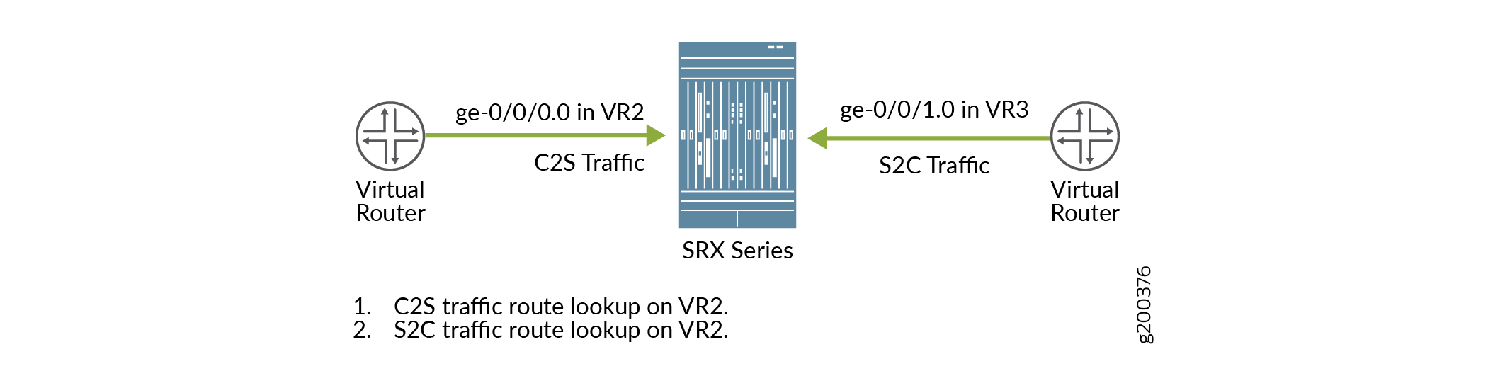
Figure 2 shows the behavior of the packet flow when the reverse-route-packet-mode-vr command is configured using interface. The client to server traffic
uses the routing instance VR2 of incoming interface ge-0/0/0.0 to
route the traffic. The server to client traffic uses the routing instance
VR3 of interface ge-0/0/1.0 to route the traffic.
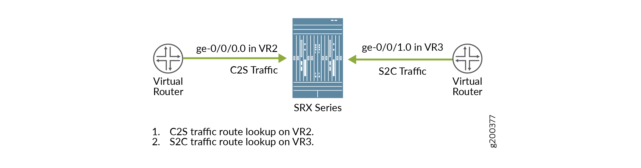
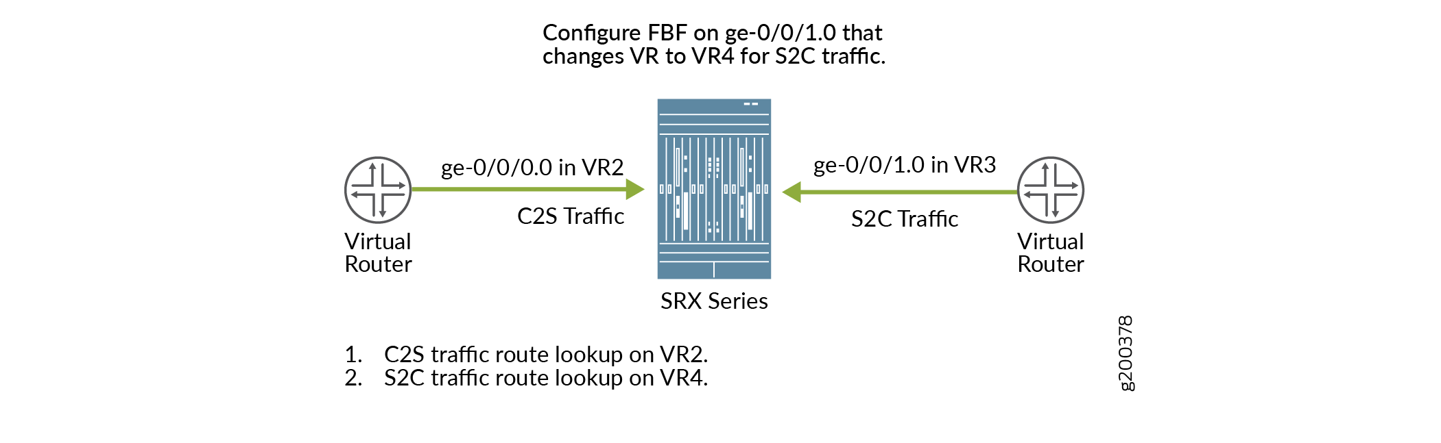
Figure 3 shows the behavior of the packet flow when the reverse-route-packet-mode-vr command is configured using FBF. The client to server traffic uses
the packet incoming interface ge-0/0/0.0 in VR2 to route the traffic.
Configuring FBF on the interface ge-0/0/1.0 changes VR3 to VR4. The
server to client traffic uses VR4 to route the traffic.
Understanding To-host Traffic on Virtual Router
On a SRX Series Firewall, all the traffic that passes the firewall filter is referred as to-host traffic. The traffic from the firewall to the device is referred as the from-host traffic. The to-host traffic uses an egress interface and the from-host traffic uses an ingress interface. If both the interfaces are not in the same routing instance, there will be a session mismatched. To overcome this issue, the to-host and the from-host traffic choose interfaces that are available in the same routing instance.
Figure 4 shows the to-host traffic using the routing instance VR5 of interface ge-0/0/0.0 and the routing instance VR6 of destination interface lo0.1.

For example, if the to-host traffic uses a local interface (such as local....X) that is in routing instance 5 (VR5), and the from-host traffic uses the interface in routing instance 6 (VR6). The session output displaying the interface information of the to-host traffic is:
Session ID: 10000179, Policy name: pol1/4, Timeout: 2, Valid
  In: 192.168.90.1/4 --> 192.168.91.1/19050;icmp, Conn Tag: 0x0, If: xe-9/0/3.0, Pkts: 1, Bytes: 84, CP Session ID: 10000178
  Out: 192.168.91.1/19050 --> 192.168.90.1/4;icmp, Conn Tag: 0x0, If: .local..5, Pkts: 1, Bytes: 84, CP Session ID: 10000178
The session output displays the local interface of the to-host traffic as local....5.
To synchronize the to-host and from-host traffics, the to-host traffic uses traffic destination IP interface (lo0.1) that is available in VR6. As the from-host traffic is using the interface available in VR6, the session matches. The session output displaying the interface information of the to-host traffic is:
Session ID: 10000179, Policy name: pol1/4, Timeout: 2, Valid
  In: 192.168.90.1/4 --> 192.168.91.1/19050;icmp, Conn Tag: 0x0, If: xe-9/0/3.0, Pkts: 1, Bytes: 84, CP Session ID: 10000178
  Out: 192.168.91.1/19050 --> 192.168.90.1/4;icmp, Conn Tag: 0x0, If: .local..6, Pkts: 1, Bytes: 84, CP Session ID: 10000178
The session output displays the local interface of the to-host traffic as local....6.