Inband Flow Analyzer (IFA) 2.0 Real-Time Flow Monitoring
Inband Flow Analyzer (IFA) 2.0 collects data on a per-hop basis across the network. You export this data to external collectors to perform localized or end-to-end analytics.
Inband Flow Analyzer 2.0
- Inband Flow Analyzer 2.0 Overview
- Benefits
- Modes (Junos OS Evolved only)
- Inband Flow Analyzer Process
- IFA Probe Packet Headers
- Tailstamps for IFA Probe Packets (QFX5220 only)
- Supported Features on IFA Nodes
- Limitations of IFA 2.0 Configuration
- Usage Considerations
Inband Flow Analyzer 2.0 Overview
Inband Flow Analyzer 2.0 (IFA 2.0) is a feature that you can use to monitor and analyze packets as they enter and exit the network. As the network administrator, you can use this feature to collect data related to the paths the packets take through the network and how long the packets spend at each hop. This data provides an indication of excessive latency and possible congestion. This feature helps you to get insights about complex networks by collecting per-hop flow data on the data plane.
IFA collects network-wide flow data using either live mode or probe mode. When the node operates in live mode, the software inserts the IFA base header and IFA metadata into the live packets. When the node operates in probe mode, the software samples the live packet flow and copies the sampled packet to create the initial packet that carries the IFA layers. These probe packets are representative of the original flow, possessing the same characteristics as the original flow. This means that IFA probe packets traverse the same path in the network and the same queues in the networking element as the original live packet would. As a result, IFA probe packets traverse the same network path as the original flow, experiencing similar latency and congestion.
You can use Inband Flow Analyzer 2.0 (IFA 2.0) to collect flow data information such as:
Residence time (latency)
Per-hop latency
Per-hop ingress port number
Per-hop egress port number
Received packet timestamp value
Queue ID
Congestion notification
Egress port speed
IFA 2.0 is defined in the IETF draft titled Inband Flow Analyzer, draft-kumar-ippm-ifa-02.
See Feature Explorer: Inband Flow Analyzer (IFA) 2.0 to confirm platform and release support.
Benefits
- IFA probe packets traverse the same network path as the original flow, helping you to monitor the network for faults and performance issues.
- Monitors live traffic and thus helps to perform packet-level latency analysis and queue-congestion monitoring to optimize the network performance.
Modes (Junos OS Evolved only)
Starting in Junos OS Evolved Release 25.4R1, we support two modes for the IFA 2.0 feature. The new modes are as follows:
In live mode, for those switches that support it, IFA 2.0 uses the original packets as IFA packets.
In probe mode, IFA 2.0 uses copies of the original packets as the IFA probe packets. This mode is the default.
When you configure an IFA initiator node to initiate IFA packets:
In live mode, the initiator inserts IFA headers and metadata into the live packets.
In probe mode, the initiator samples the flow and copies that sample to create the probe.
When you configure an IFA terminator node to parse the IFA header in the packet:
If it is a live packet, then the terminator strips the IFA layer and forwards the modified live packet to its destination. The terminator also sends a mirror copy of the IFA packet, with all of the IFA metadata, to the IFA collector.
If the packet is a probe packet, then the terminator drops the packet and sends a mirror copy to the collector with all the IFA metadata.
To specify the mode, configure the mode (live | probe) statement at the [edit services inband-flow-telemetry] hierarchy level. The default mode is probe. Use the show services inband-flow-telemetry global command to see results that include the mode information.
Inband Flow Analyzer Process
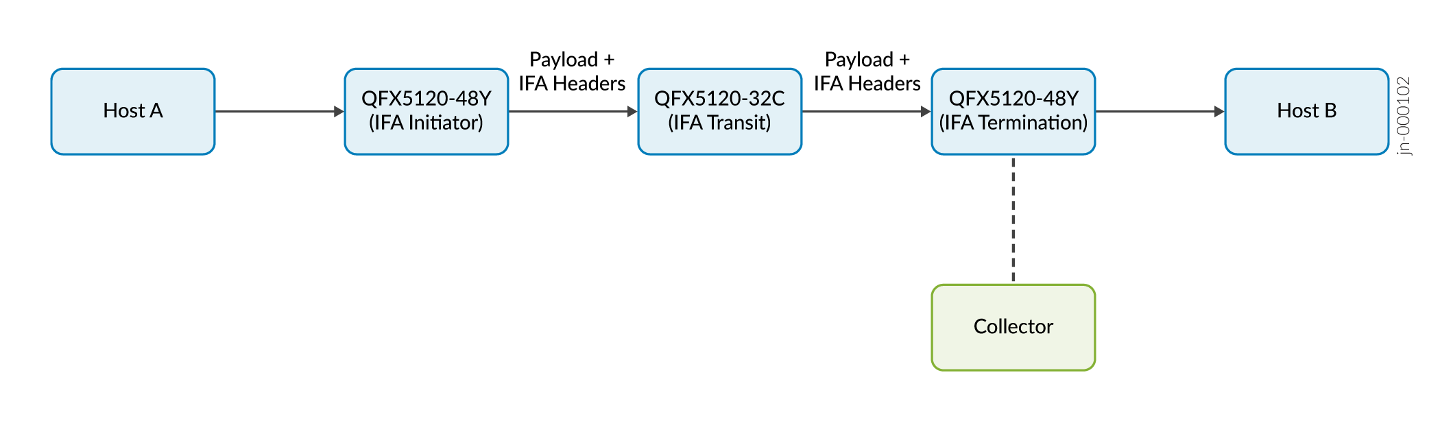
IFA uses the following processing nodes (as shown in Figure 1) to monitor and analyze flows:
IFA initiator node (also known as ingress node)
IFA transit node
IFA terminator node (also known as egress node)
IFA 2.0 supports processing both Layer 3 (L3) and VXLAN flows, but you can't configure IFA for both L3 and VXLAN flows on the same device. The flow-type options are mutually exclusive. You use the flow-type configuration statement to set the flow type of interest —either L3 or VXLAN. You configure the flow-type statement only for the IFA initiator and IFA terminator nodes (generally leaf nodes). For an IFA transit node (generally a spine node), you don't need to configure the flow-type statement.
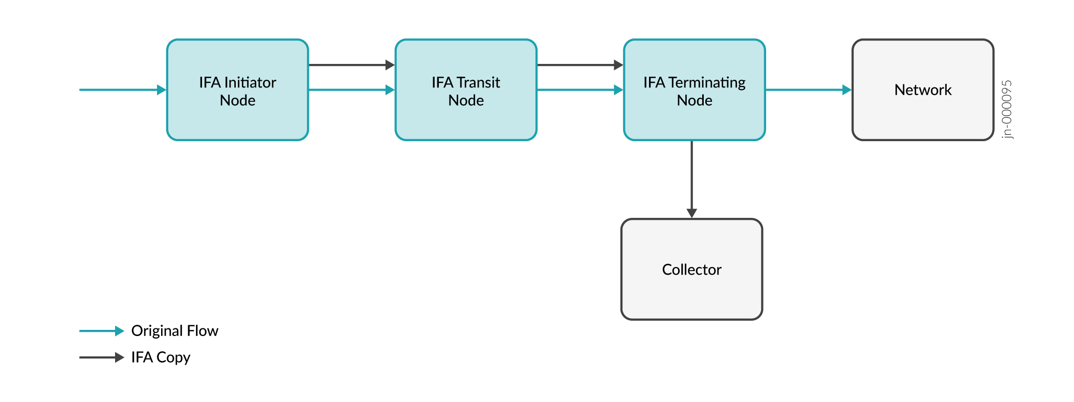
Table 1 summarizes the different functions that the IFA processing nodes perform:
| IFA Node | Function |
|---|---|
IFA initiator node |
Samples the flow traffic of interest (L3 or VXLAN) and creates an IFA copy by adding an IFA header to each sample. If you configured live mode, the initiator inserts IFA headers and metadata into the live packets. |
IFA transit node |
Identifies IFA packets and appends their metadata to the metadata stack in the packet.
|
IFA terminator node |
Note:
IFA terminator functionality requires a valid Juniper Advanced Telemetry Feature (ATF) license. The QFX5240 switch does not need a license for IFA termination. |
IFA Probe Packet Headers
An IFA 2.0 probe packet contains the following:
-
IFA Header
-
IFA Metadata Header
-
IFA Metadata Stack
Figure 2 shows the L3 IFA 2.0 packet format at the IFA initiator node:
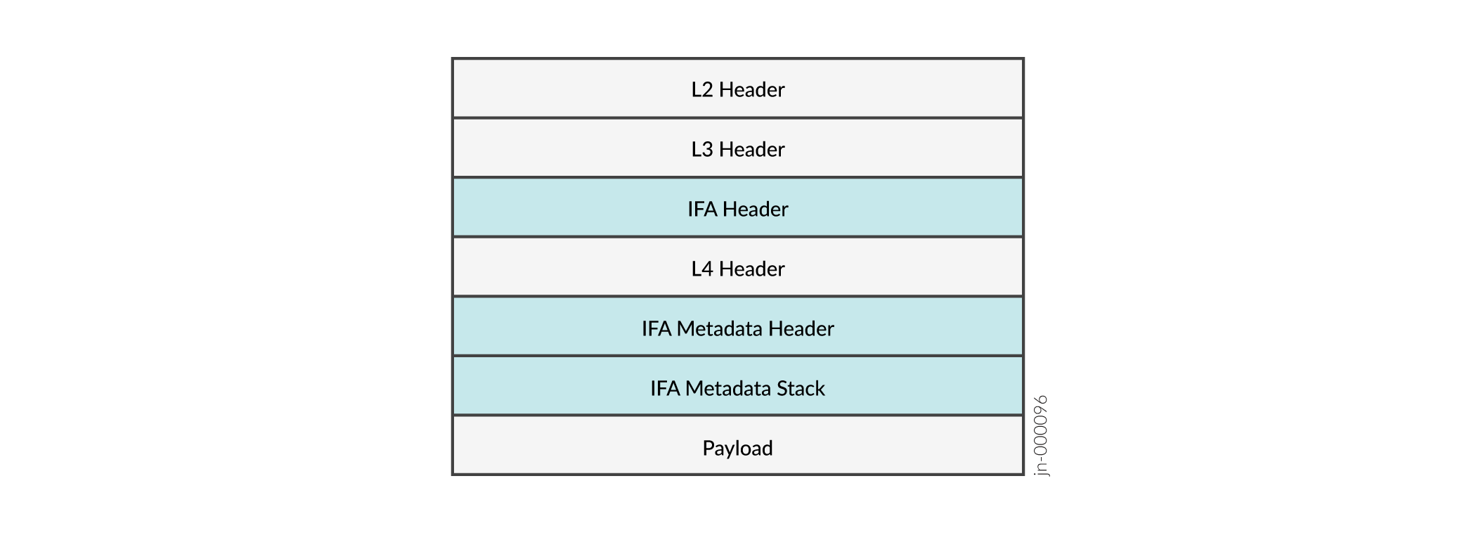
Figure 3 shows the VXLAN IFA 2.0 packet format at the IFA initiator node.
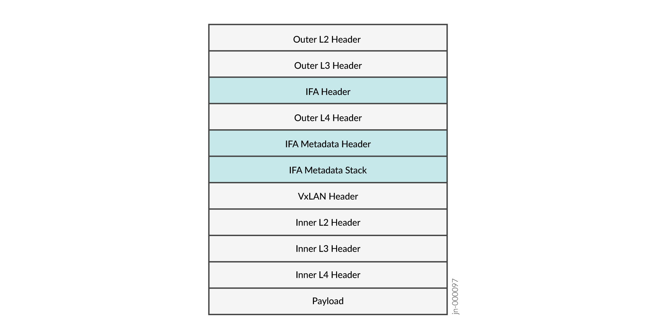
When VXLAN is used, then the IFA headers are added after VXLAN encapsulation using a three-pass mechanism.
IFA Header
IFA 2.0 defines an upper layer header (ULH), similar to how TCP, UDP, Generic
Routing Encapsulation (GRE), and Spanning Tree Protocol (STP) define a ULH. The
IFA ULH is always the first header after the IP header, even if there are some
other IPv4 extension headers. The NextHdr field (that is, the
Protocol Type field in the IFA header) carries the original
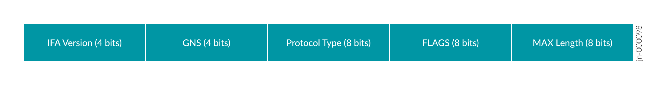
IP header protocol field value. Figure 4 shows the IFA header format.
| IFA Header Field | Description |
|---|---|
|
IFA Version |
Version of the IFA header. In the current implementation, the IFA version is 2.0. |
|
GNS |
Global namespace (GNS) for IFA metadata. The IFA initiator node sets the value for this field as 0xF. |
|
Protocol Type |
IP header protocol type. This value is copied from the IP header. |
|
FLAGS |
Unused |
|
MAX Length |
Maximum allowed length of the metadata stack in multiples of four octets. The initiator node initializes this field. Each node in the path compares the current length with the maximum length. If the current length equals or exceeds the maximum length, the transit node stops inserting metadata. You can configure this maximum allowed length. The default value is 240 octets (for 30 hops). |
IFA Metadata Header
IFA 2.0 defines a compact 4-byte metadata header as shown in Figure 5. The IFA initiator node adds this header to the probe packet.

| IFA Metadata Header Field | Description |
|---|---|
|
Request Vector |
Specifies the presence of fields as specified by the GNS. Unused. |
|
Action Vector |
Specifies the node-local or the end-to-end action on the IFA packets. Unused. |
|
Hop Limit |
Specifies the maximum number of allowed hops in an IFA zone. The initiator node initializes this field. The hop limit is decremented at each hop. If the hop limit of the incoming packet is 0, the current node does not insert metadata. You can configure this limit. The default value is 250. The terminator node does not perform the hop limit check. |
|
Current Length |
Specifies the current length of the metadata stack in multiples of 4 octets. |
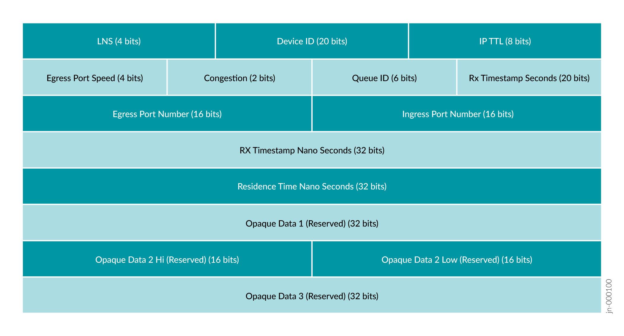
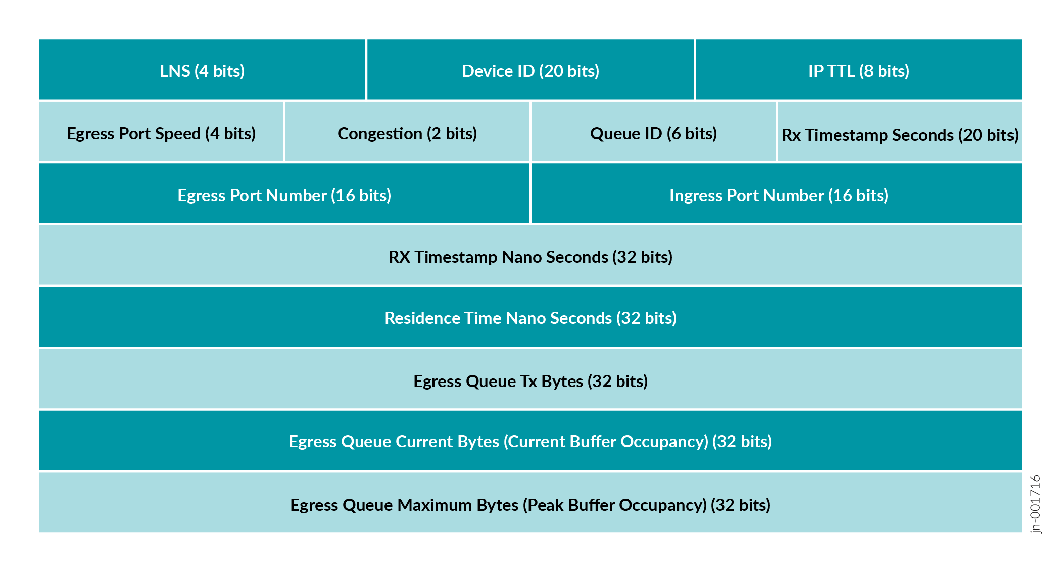
IFA Metadata Stack
For Junos OS and for supported releases of Junos OS Evolved released before 2026, each IFA hop inserts hop-specific metadata into an IFA metadata stack as shown in Figure 6. For Junos OS Evolved Release 25.2X100-D20 and Release 26.2R1, as shown in Figure 7, 3 egress-queue related fields have been added to the IFA metadata stack:
-
Egress Queue Tx Bytes
-
Egress Queue Current Bytes (Current Buffer Occupancy)
-
Egress Queue Maximum Bytes (Peak Buffer Occupancy)
The IFA initiator node adds the metadata header after the L4 header.
Exceptions:
-
The QFX5220 as a transit node can not insert metadata into the metadata stack of the IFA probe packet header. Instead, the QFX5220 adds a tailstamp to the end of the IFA probe packet that includes timestamps and other metadata. For more information about these tailstamps, see Tailstamps for IFA Probe Packets (QFX5220 only).
-
The Egress Port Speed field in the IFA 2.0 Metadata stack is not supported on the QFX5230. The value in the field is always '0' irrespective of the egress port speed.
| IFA Metadata Stack Header Field | Description | ||||||||
|---|---|---|---|---|---|---|---|---|---|
|
LNS |
Local namespace. You must set the LNS value to 1. |
||||||||
|
Device ID |
User-configurable device ID. You can explicitly configure the
device ID or configure the |
||||||||
|
IP TTL |
IP time-to-live (TTL) value at each hop. |
||||||||
|
Egress Port Speed |
Encodings are 0–10Gbps, 1–25Gbps, 2–40Gbps, 3–50Gbps, 4–100Gbps, 5–200Gbps, 6–400Gbps, 7–800Gbps. Egress port speed is mapped with IFA metadata. For example, when a egress port speed is 10Gbps, then the speed field of IFA packet is set to 0. |
||||||||
|
Congestion |
Indicates whether the packet has experienced congestion. You must enable an explicit congestion notification (ECN) on the egress port. |
||||||||
|
Queue ID |
Egress port queue ID. |
||||||||
|
Rx Timestamp Seconds |
Received packet timestamp value (in seconds). It is the
collector's responsibility to retrieve time-of-day (ToD)
from these 20-bit values. 20-bit seconds will wrap around
every 12 days. Collector has to periodically sync up ToD
within the wraparound time and use it along with 20-bit from
metadata to derive the 32-bit |
||||||||
|
Egress Port Number |
Egress hardware (ASIC) port number. |
||||||||
|
Ingress Port Number |
Ingress hardware port number. |
||||||||
|
Rx Timestamp Nano Seconds |
Received timestamp value in nanoseconds. This timestamp is the exact value after the timestamp in seconds. Add this to the Rx Timestamp Seconds value to get the exact timestamp with nanoseconds precision. |
||||||||
|
Residence Time Nano Seconds |
Per-hop latency in nanoseconds. For the QFX5120, the residence time is calculated as 0x3B9ACA00 (1 second in nanoseconds) + TX_NSEC - RX_NSEC. (An extra second is added to every packet to avoid wraparound handling.) In contrast, for the QFX5130, QFX5220, QFX5230, QFX5240, QFX5241, and QFX5700, the residence time is updated as the actual value. |
||||||||
|
Egress Queue Tx Bytes |
Indicates the egress port queue transmit bytes. |
||||||||
|
Egress Queue Current Bytes (Current Buffer Occupancy) |
Indicates the current buffer occupancy of the egress port queue in multiples of cell size of 254 bytes.
For example, a value of 0x00200002 would imply that the current buffer occupancy of the egress queue is 2*254 = 508 bytes. |
||||||||
|
Egress Queue Maximum Bytes (Peak Buffer Occupancy) |
Indicates the peak buffer occupancy of the egress port queue in multiples of cell size of 254 bytes.
For example, a value of 0x00400004 would imply that the peak buffer occupancy of the egress queue is 4*254 = 1016 bytes. |
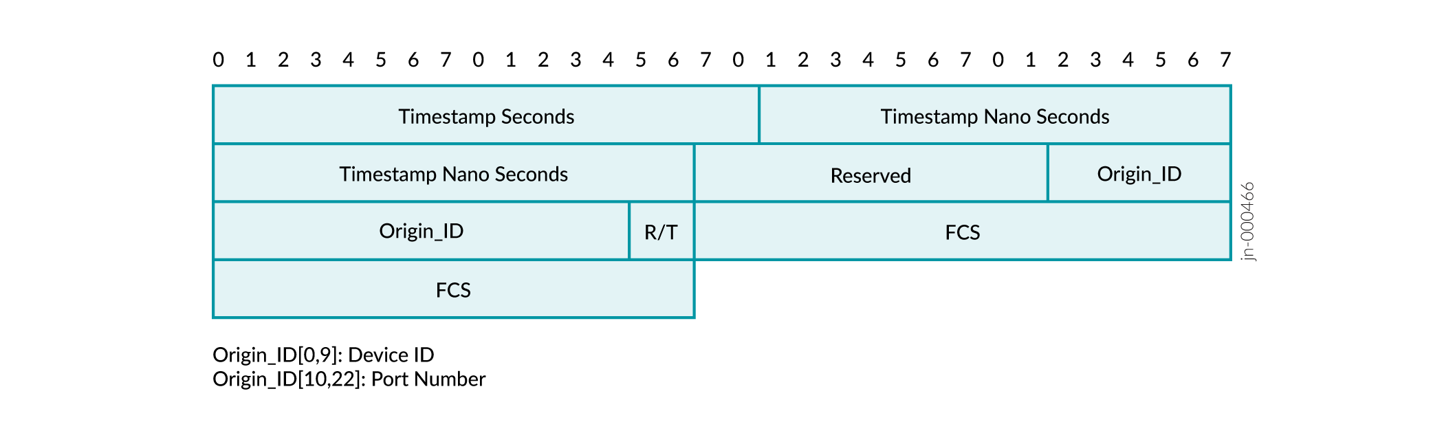
Tailstamps for IFA Probe Packets (QFX5220 only)
The QFX5220 as a transit node can not insert metadata into the metadata stack of the IFA probe packet header. Instead, the QFX5220 adds a tailstamp to the end of the IFA probe packet that includes timestamps and other metadata. The QFX5220 adds a total of 28 bytes of metadata as a tailstamp. Upon receiving the IFA probe packet, the IFA termination node uses the TTL value in the metadata to identify the number of tailstamps (that is, the number of QFX5220 hops on the path between two QFX5120 or QFX5130 devices). Then the tailstamps are converted into the correct metadata format and inserted into the correct place in the metadata stack, so that the metadata appears in the order that the transit nodes added them. Once complete, the IFA termination node exports the data in IPFIX format to the configured external collector.
Due to this inability to insert metadata into the stack, the IFA metadata stack fields IP TTL , Egress Port Speed and Congestion for the QFX5220 are received with the value of 0 at the collector. You must configure the collector to ignore these unsupported fields from the QFX5220.
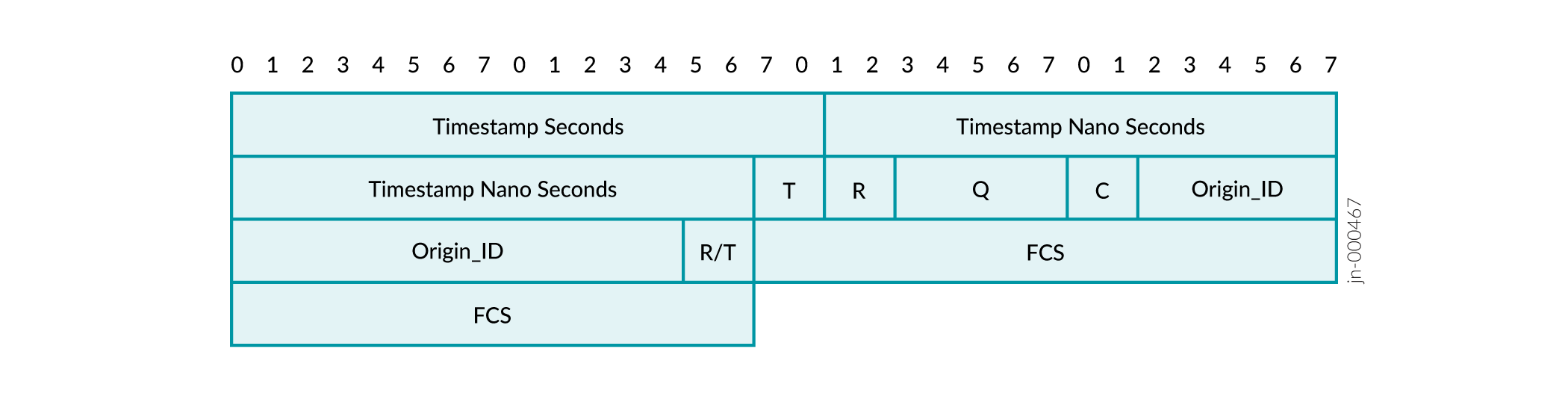
The tailstamp includes 14 bytes of ingress (Rx) tailstamp and 14 bytes of egress (Tx) tailstamp. Figure 8 and Figure 9 provide details about the format of these timestamps.
Supported Features on IFA Nodes
Table 5 lists the features supported by IFA nodes.
| IFA Node | Supported Features |
|---|---|
IFA initiator |
Traffic and interface types:
|
IFA transit |
Identifies IFA packets, appends their metadata, and forwards it. |
IFA terminator |
|
Supported IFA 2.0 IPFIX Format (Terminator Node)
The terminator node formats the IFA 2.0 packets in IPFIX format, updates the egress port information, and sends the packet to the configured collector. The IFA 2.0 IPFIX template is the same for L3 traffic and VXLAN traffic. Figure 10 shows the IPFIX template in which the terminator node formats the IFA 2.0 data and sends it to a collector.
You cannot use the QFX5220 switch as an IFA transit node when a QFX5240 switch is the IFA terminator mode.
The QFX5240 switch does not use these IPFIX templates. Instead, the QFX5240 switch terminates the IFA packet, mirror encapsulates it, and sends one IPFIX PSAMP packet to the collector for each IFA packet. The PSAMP packet contains the destination MAC address of the collector, the source MAC address of the collector, the user-configurable source IP address, the user-configurable destination IP address, the UDP source port, the user-configurable UDP destination port, the IPFIX PSAMP header, and the MAC source and destination addresses of either the IFA or the original packet. These fields are followed by the IP layer header, IFA header, L4 layer (UDP/TCP) header, IFA metadata header and IFA metadata stack, and the payload.
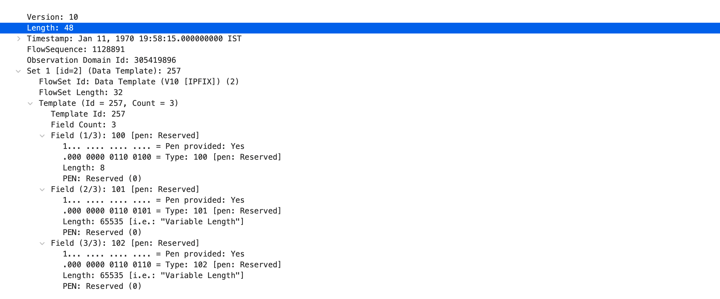
Figure 11 shows the template for an IFA 2.0 IPFIX PSAMP packet received by the collector.
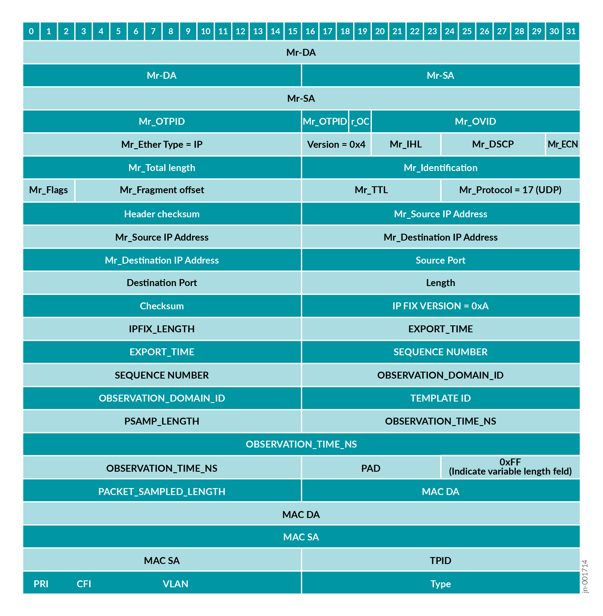
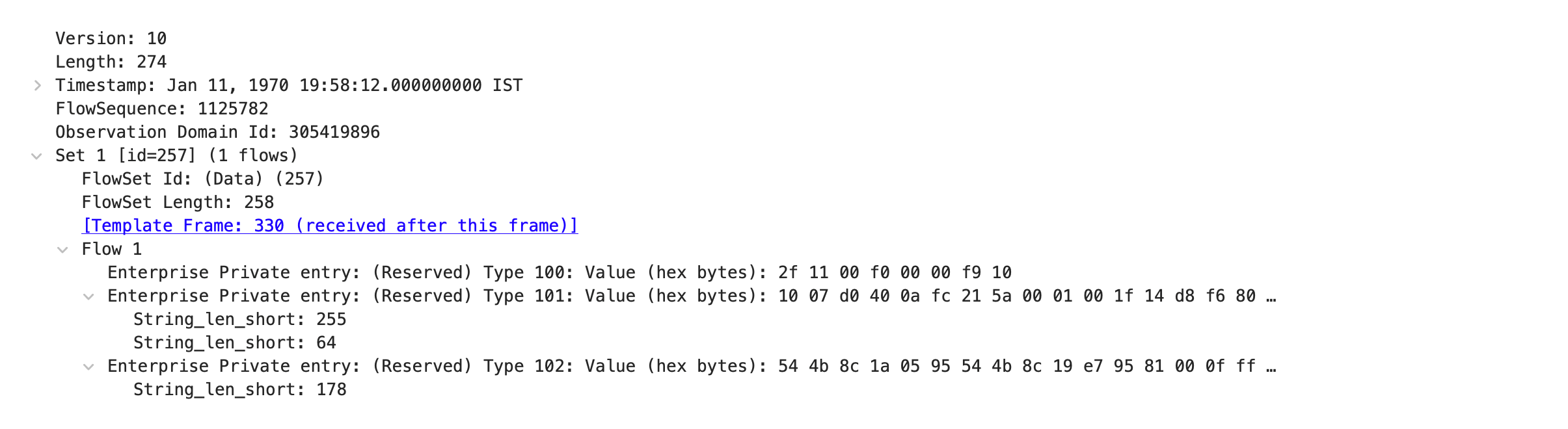
Figure 12 shows a sample VXLAN IFA 2.0 packet received by the configured collector in IPFIX format.
Limitations of IFA 2.0 Configuration
Before you configure IFA 2.0 on a device running Junos OS, you must be aware of the following limitations:
Protocol Number—IFA 2.0 uses the experimental protocol number 253. If the switch receives any traffic with protocol number 253, those packets will hit the IFA transit filter. In this case the QFX5220 adds a 28-byte tailstamp to those packets. For the QFX5130, QFX5230, QFX5240, QFX5241, and QFX5700 switches, even though the packets hit the filter, IFA metadata is not added to the packets. However, the IFA transit statistics do increment.
Filter Resource Allocation—If filter hardware resources are already exhausted in the system, the IFA feature does not work because it needs filter resources. You can monitor the system log (syslog) for filter space exhaustion errors.
Layer 2 and BUM Traffic—IFA 2.0 is not supported on Layer 2 switched traffic and broadcast, unknown unicast, and multicast (BUM) traffic.
IFA Layer 3 and VXLAN Flows
IFA 2.0 supports processing both L3 and VXLAN flows, but you can't configure IFA for both L3 and VXLAN flows on the same device. The
flow-typeoptions are mutually exclusive. You use theflow-typeconfiguration statement to set the flow type of interest —either L3 or VXLAN. This restriction is only applicable for IFA initiator and terminator nodes (generally leaf nodes). For IFA transit nodes (generally spine nodes), it is not required to configure the flow type.(For QFX5120 switches only) For a VXLAN IFA flow, the egress port-related metadata for the terminator node (including egress port number, speed, queue ID, and congestion) are incorrect. It is recommended that you ignore the terminator node egress-port-related metadata for VXLAN flows.
(For QFX5240 switches only) For VXLAN flows, IFA terminated packets sent to the collector contain metadata from only the initiator node and all the transit nodes. These packets do not contain metadata from the terminator node.
- An IFA flow-type (L3 or VXLAN) change requires IFA filter removal and reconfiguration. In case of a flow-type mismatch (for example,
flow-typeconfigured as VXLAN, whereas the incoming traffic is L3 or vice versa), we can't guarantee IFA behavior (IFA packets could be initiated with invalid fields).
IFA Initiator Node
L4 header (UDP/TCP) is mandatory for IFA initiation.
IFA initiation for VXLAN flow does not work if the egress port is configured to function as a link aggregation group (LAG) (links connecting leaf to spine).
IFA Transit Nodes—Devices running Junos OS and Junos OS Evolved do not support the maximum length check for the metadata stack. Configure the
hop-limitoption to limit the insertion of metadata on transit nodes. The QFX5220 transit node cannot perform the hop-limit check to insert the tailstamp. The QFX5220 transit node also cannot insert metadata into the metadata stack in the IFA probe packet header; instead, the QFX5220 transit node appends a tailstamp to the end of the IFA probe packet.The QFX5220 transit node supports only 18 bits for the
Rx Seconds
                                Timestamp
value. The QFX5130, QFX5230, QFX5240, QFX5241, QFX5250, and QFX5700 transit nodes support a 20-bitRx Seconds Timestampvalue.The
Residence Time Nano Secondsfield is updated as the actual value on the QFX5220, QFX5230, QFX5240, QFX5241, QFX5250, QFX5130, and QFX5700 transit nodes, but on the QFX5120 transit node, 1 second (1000000000 ns) is added along with the actual residence time. IFA Terminator Node
You can configure only a single IPv4 collector at the terminator node.
(QFX5120 terminator nodes only) The terminator node metadata has the queue ID 47. This queue ID is reserved for IFA packet export.
(QFX5120 terminator nodes only) The terminator node does not perform a hop-limit check. Even if the incoming IFA packet has
hop-limitset to 0, the terminator node inserts the metadata and reduces the hop limit by 1, which resets thehop-limitvalue to 255.
Usage Considerations
Following are the IFA 2.0 related usage considerations:
Sampled IFA packets have an additional 40 bytes (4-byte IFA header + 4-byte IFA metadata header + 32-byte metadata) when it egresses on the initiator node. On subsequent IFA nodes, 32-byte IFA metadata is inserted at every hop. Due to insertion of per-hop metadata into IFA packets, the packet size grows after every hop. You must configure the interface's maximum transmission unit (MTU) accordingly along the network path. In case of an IFA zone with a large number of transit nodes, you must take care of the MTU. Alternatively, you can configure the
hop-limitoption at the initiator node to ensure that the size of the IFA packets never exceeds the specified MTU value.To select the flow of interest, you can use any combination of source IP address, destination IP address, source port, destination port, and protocol match qualifiers. For VXLAN termination on a terminator node, use the outer source IP address and destination IP address as match qualifiers. IFA 2.0 doesn't support any other match qualifiers for the QFX5120 switch. For a QFX5240 terminator node, we recommend that you use any combination of the outer source IP address and destination IP address, source port, destination port, and protocol as match qualifiers, but you can also use any other available match qualifiers under the term to select a flow.
Another option is to configure the initiation or termination filter without any qualifiers. In this case, all incoming IFA packets on the port are initiated or terminated.
You must configure a unique device ID for each hop within an IFA zone. If you've configured the
autooption for the device ID, then the device ID is generated from the last 20 bits of the router ID or management IP address.If you've configured the sampling rate as
aggressive, the egress ports might experience congestion due to more IFA copies. This port congestion could create congestion on terminator nodes when IFA copies are sent to the chip processor for IPFIX export. We recommend that you select the sampling rate accordingly.When you configure an IFA 2.0 initiator, an internal mirror session is created for the loopback port. As a result, the number of user-configurable mirror sessions reduces from 4 to 3 on the QFX5120 switch or reduces from 8 to 7 on the QFX5240 switch.
The terminator node accepts an IFA packet size up to 9000 bytes (including IFA headers). On the terminator node, multiple IFA received packets are combined into a single IPFIX export packet. You can combine a maximum of 10 IFA records in a single IPFIX export packet. By default, a maximum of 256 bytes of the original flow packet are exported as part of the IPFIX export, along with IFA headers. The maximum size of a single IPFIX packet is 9000 bytes. You must configure the MTU properly on the collector port. Because the maximum size of a single IPFIX packet is 9000 bytes, the maximum clip length for the IPFIX packet is equal to or less than: 9000 bytes - (IFA header length + IFA metadata header length + IFA metadata stack length).
On a QFX5240 terminator mode, for both live and probe mode, the entire IFA packet is mirror encapsulated using IPFIX PSAMP format, for both Layer 3 and VXLAN flows. The software sends one IPFIX PSAMP packet to the collector for each IFA packet.
We recommend that you use only IFA-aware (supported) devices within the IFA zone. We cannot guarantee proper IFA behavior with IFA-unaware devices.
Configure Inband Flow Analyzer 2.0
IFA is a type of Inband Network Telemetry (INT) that allows you to collect information about the network state by the data plane.
To configure IFA 2.0 for monitoring the network for faults, performance issues, and collect the data for analysis, you need to configure the IFA roles first. You can configure the IFA roles on a Junos OS or Junos OS Evolved device that supports the IFA feature. See Feature Explorer: Inband Flow Analyzer (IFA) 2.0 for supported devices.
Table 6 describes the interoperability of the QFX5240 switch with other supported devices for IFA initiator, transit, and terminator roles:
| IFA initiator | IFA transit | IFA terminator |
|---|---|---|
QFX5240, live or probe mode |
QFX5120, QFX5130, QFX5230, QFX5240, QFX5241, and QFX5250 |
QFX5240 (mode is not configured on a terminator node) |
QFX5240, probe mode |
QFX5120, QFX5130, QFX5220, QFX5230, QFX5240, QFX5241, and QFX5250 |
QFX5120 (we support only probe mode on this platform) Note: For a QFX5220 transit node, we support only the QFX5120 switch as the terminator node because the QFX5120 switch can convert tailstamps into metadata.
|
QFX5120 (we support only probe mode on this platform) |
QFX5120, QFX5130, QFX5230, QFX5240, QFX5241, and QFX5250 |
QFX5240 (mode is not configured on a terminator node) |
QFX5120 (we support only probe mode on this platform) |
QFX5120, QFX5130, QFX5220, QFX5230, QFX5240, QFX5241, and QFX5250 |
QFX5120 (we support only probe mode on this platform) |
Following are some of the guidelines for configuring a Junos OS device for an IFA role:
- You can use the same model switches or different switches to play the IFA roles (initiator, transit, terminator) for a particular IFA flow.
- You can use the same device to perform all three different IFA roles for different flows.
- In an IFA flow, the transit IFA role is optional.
Figure 13 illustrates a sample scenario for configuring IFA nodes on Junos OS devices. In this scenario, different Junos OS devices that support the IFA feature play different IFA roles in a single IFA flow.
Following are some of the guidelines for configuring IFA nodes:
- You can enable the IFA configuration on the interface only through the firewall filter configuration.
- You can apply IFA filter only on ingress direction on the port.
Table 7 summarizes the configurations for IFA initiator, transit, and terminator nodes.
IFA Configuration Parameter |
Configuration Statement |
IFA Role |
|---|---|---|
(Mandatory) Configure Device ID |
user@host# set services inband-flow-telemetry device-id (<1 - 1048575> | auto) |
Mandatory configuration for IFA initiator, transit, and terminator nodes. |
(Optional, QFX5120-48YM or QFX5220 only) Configure a more accurate clock source |
user@host# set services inband-flow-telemetry clock-source (ntp|ptp) |
IFA initiator, transit, and terminator nodes. |
(Optional) IFA maximum metadata stack length |
user@host# set services inband-flow-telemetry meta-data-stack-length <8 - 255> Default value : 240 (for 30 hops) |
IFA initiator node |
(Optional) IFA maximum hop limit |
user@host# set services inband-flow-telemetry hop-limit <1 - 250> Default value : 250 |
IFA initiator node |
(Optional) No IPv6 address match |
user@host# set services inband-flow-telemetry no-ipv6-address-match |
IFA initiator/terminator node |
(Mandatory) IFA flow type |
user@host# set services inband-flow-telemetry flow-type (l3 | vxlan) |
Mandatory configuration for IFA initiator and terminator node. This configuration is not required for IFA transit node. |
| (Optional) Mode | user@host# set services inband-flow-telemetry mode (live | probe) Probe mode is the default. Therefore, you do not need to configure this statement unless you want to configure live mode on a device that supports that feature. |
IFA initiator node |
IFA sampling |
user@host# set services inband-flow-telemetry profile ifa-profile-name sample-rate <1-16777215> |
IFA initiator node |
Collector information |
user@host# set services inband-flow-telemetry profile ifa-profile-name collector source-address IP-address user@host# set services inband-flow-telemetry profile ifa-profile-name collector destination-address IP-address user@host# set services inband-flow-telemetry profile ifa-profile-name collector destination-port port-number user@host# set services inband-flow-telemetry profile ifa-profile-name collector maximum-clip-length length user@host# set services inband-flow-telemetry profile ifa-profile-name collector mtu size |
IFA terminator node |
IFA filter for L3 flow |
For example: user@host# set firewall family inet filter f1 term t1 from match-condition user@host# set firewall family inet filter f1 term t1 then inband-flow-telemetry-init p1 user@host# set firewall family inet filter f1 term t2 from match-condition user@host# set firewall family inet filter f1 term t2 then inband-flow-telemetry-terminate p2 user@host# set interfaces (interface-name | wildcard) unit 0 family inet filter input f1 |
IFA initiator/terminator node |
IFA filter for VXLAN flow |
For example: user@host# set firewall family ethernet-switching filter f1 term term1 from match-condition user@host# set firewall family ethernet-switching filter f1 term t1 then inband-flow-telemetry-init p1 user@host# set firewall family ethernet-switching filter f1 term t2 from match-condition user@host# set firewall family ethernet-switching filter f1 term t2 then inband-flow-telemetry-terminate p2 user@host# set interfaces (interface-name | wildcard) unit 0 family ethernet-switching filter input f1 |
IFA initiator/terminator node |
- Configure IFA Initiator Node
- Configure IFA Transit Node
- Configure IFA Terminator Node
- View Inband Flow Analyzer Statistics
Configure IFA Initiator Node
To configure your device as IFA 2.0 initiator:
Configure IFA Transit Node
To configure your device as IFA transit node:
auto for device-id. If the device-id is configured as auto, then the device-id is internally generated from the router ID or the management IP address. user@host# set services inband-flow-telemetry device-id (id-number | auto)
For example:
user@host# set services inband-flow-telemetry device-id 10001
Configure IFA Terminator Node
To configure your device as IFA terminator node:
View Inband Flow Analyzer Statistics
You can view the following IFA related information:
- IFA statistics using the
show services inband-flow-telemetry statsoperational mode command. - IFA global parameters using the
show services inband-flow-telemetry globaloperational mode command. - IFA-configured profiles using the
show services inband-flow-telemetry profileoperational mode command.
You can clear the IFA statistics using clear inband-flow-telemetry stats operational mode command.
IFA statistics are retrieved directly from the PFE and are not maintained in the Routing Engine. Therefore, a PFE-process restart clears the IFA statistics and a Routing-Engine process restart does not impact the IFA statistics.
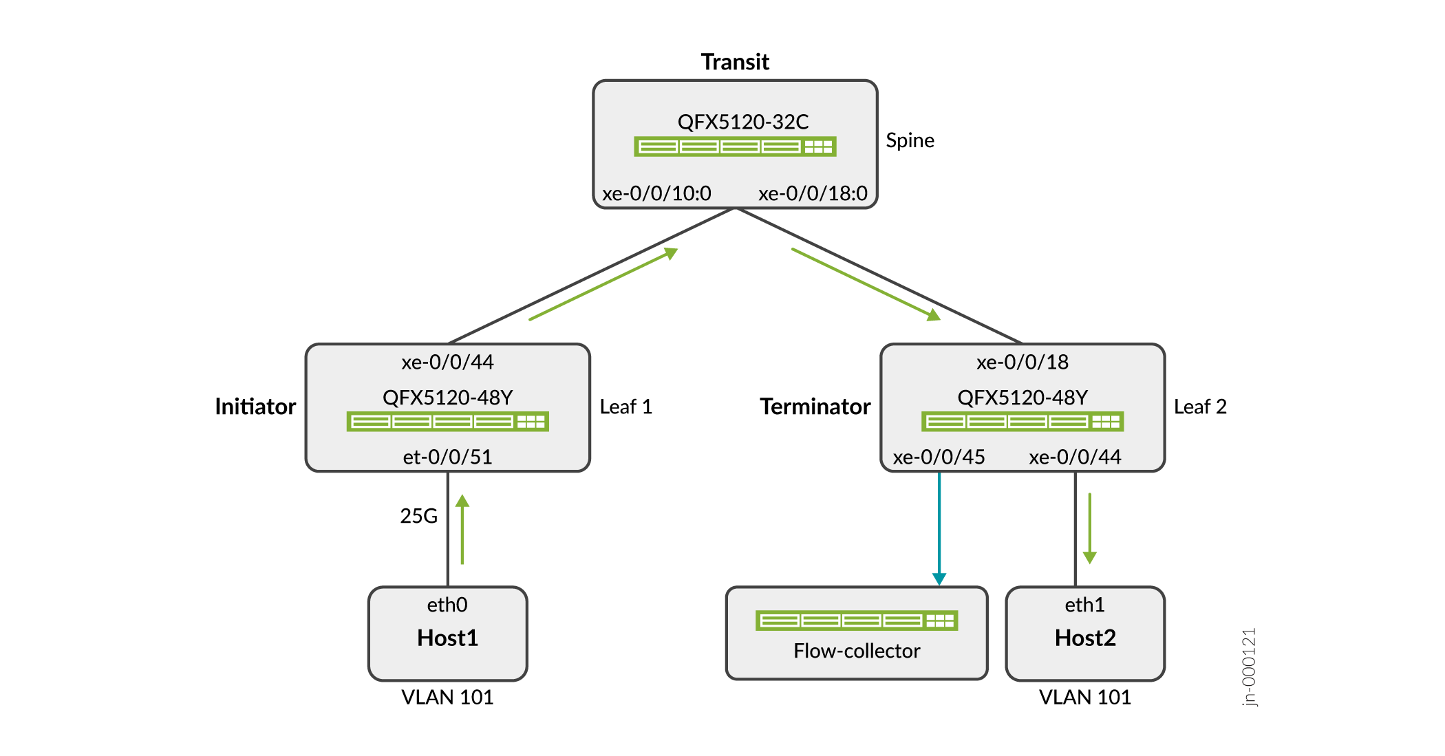
Example - Configure Inband Flow Analyzer 2.0 for Traffic Monitoring
Use this example to configure the IFA 2.0 nodes on your QFX Series switches that enable analyzing of Layer 3 or VXLAN traffic flows. Figure 14 shows the topology where IFA 2.0 is configured on QFX Series switches that support the IFA 2.0 feature. In this topology, VXLAN traffic is monitored at the initiator and data is collected at the terminator node for analysis.
- Requirements
- Pre-Requisites
- Before you Begin
- Overview
- Configuration
- CLI Quick Configuration
- Step-by-Step Procedure
- Results
- Verification
Requirements
This example uses the following hardware and software components:
- One QFX5120-32C switch as a spine node
- Two QFX5120-48Y switches as the leaf nodes
- Junos OS Release 21.4R1
You can use other QFX Series switches in the initiator, transit, and terminator roles. See Table 6 to see what roles QFX Series switches support in IFA 2.0.
Pre-Requisites
This example assumes that you already have an EVPN-VXLAN based network and want to enable traffic monitoring on QFX switches.
Before you Begin
- Make sure you understand how EVPN and VXLAN works. See Example: Configuring IRB Interfaces in an EVPN-VXLAN Environment to Provide Layer 3 Connectivity for Hosts in a Data Center and Bridged Overlay Design and Implementation to understand EVPN-VXLAN in detail.
- For IFA terminator node configurations to take effect, you need to have a valid Advanced Telemetry Feature (ATF) license in place.
Overview
In this example, you'll configure one of the QFX5120-48Y switches (Leaf 1) as an initiator node, the QFX5120-32C switch as a transit node, and the second QFX5120-48Y switch (Leaf 2) as a terminator node. The VXLAN traffic flows from Host 1 to Host 2. Configuring IFA on the ingress and egress nodes allows you to monitor network operation and identify the performance issues.
The QFX5120-32C functions as a spine to connect the QFX5120-48Y leaf nodes. At the terminator node, you collect the sampled traffic in IPFIX format using an IPv4 collector application.
Configuration
In this example, you'll configure the following functionality on the switches:
- Configure Leaf 1 as an initiator node and configure initiator related attributes, like global device identifier and the sampling rate. Configure an IFA profile and firewall filter with the action as
inband-flow-telemetry-init, and bind the IFA firewall filter to the interfaces. - Configure the QFX5120-32C spine switch as a transit node with a global device identifier. When you configure a global device identifier, the spine device adds the IFA metadata and forwards the IFA probe packets.
- Configure Leaf 2 as a terminator node. Configure the IFA profile with the collector information and firewall filter with the action as
inband-flow-telemetry-terminate, and bind the IFA firewall filter to the interfaces.
CLI Quick Configuration
To quickly configure this example on your QFX series devices, copy the following commands, paste them into a text file, remove any line breaks, change any details necessary to match your network configuration, and then copy and paste the commands into the CLI at the [edit] hierarchy level.
Configuration on QFX5120-48Y Switch (Leaf 1 — IFA Initiator Node)
Recall that in this example you add IFA to a pre-configured EVPN-VXLAN baseline. The configuration shown here focuses on the delta needed to add IFA to the baseline. We show some of the existing configuration to best show how the IFA delta relates to the baseline.
set services inband-flow-telemetry device-id 15000
set services inband-flow-telemetry meta-data-stack-length 100
set services inband-flow-telemetry hop-limit 4
set services inband-flow-telemetry flow-type vxlan
set services inband-flow-telemetry profile ifa_profile_host1 sample-rate 1

set interfaces et-0/0/51:0 unit 0 family ethernet-switching filter input f_init

set firewall family ethernet-switching filter f_init term t1 from ip-protocol udp
set firewall family ethernet-switching filter f_init term t1 from ip-protocol tcp
set firewall family ethernet-switching filter f_init term t1 then inband-flow-telemetry-init ifa_profile_host1
set firewall family ethernet-switching filter f_init term t1 then count ifa_stats
set firewall family ethernet-switching filter f_init term t1 then accept
set firewall family ethernet-switching filter f_init term t2 then count non_ifa_stats
set firewall family ethernet-switching filter f_init term t2 then accept
Configuration on QFX5120-32C Switch (IFA Transit Node)
set services inband-flow-telemetry device-id 15001
Configuration on QFX5120-48Y Switch (Leaf 2 — IFA Terminator Node)
set services inband-flow-telemetry device-id 15002
set services inband-flow-telemetry meta-data-stack-length 100
set services inband-flow-telemetry hop-limit 5
set services inband-flow-telemetry flow-type vxlan
set services inband-flow-telemetry profile p_term collector source-address 172.16.3.1
set services inband-flow-telemetry profile p_term collector destination-address 172.16.3.2
set services inband-flow-telemetry profile p_term collector destination-port 3055

set interfaces xe-0/0/18 unit 0 family inet filter input f_term

set interfaces xe-0/0/45 description To_Collector
set interfaces xe-0/0/45 unit 0 family inet address 172.16.3.1/24

set firewall family inet filter f_term term ifa then inband-flow-telemetry-terminate p_term
set firewall family inet filter f_term term ifa then count ifa_term
set firewall family inet filter f_term term other then count non_ifa_term
set firewall family inet filter f_term term other then accept
Step-by-Step Procedure
- Configure QFX5120-48Y Switch (Leaf 1) as an Initiator Node
- Configure QFX5120-32C Switch as a Transit Node
- Configure QFX5120-48Y Switch (Leaf 2) as a Terminator Node
Configure QFX5120-48Y Switch (Leaf 1) as an Initiator Node
An IFA initiator node performs the following functions for a flow:
- Samples the flow traffic of interest based on the configuration.
- Converts the traffic into an IFA flow by adding an IFA header to each sample.
- Updates the packet with initiator node metadata.
-
Configure the IFA initiator node attributes. The traffic flow type is configured as VXLAN for initiator node. Note that you must configure the same flow type for both the initiator and the terminator node, either L3 or VXLAN. As in this example, if the VXLAN traffic flow type is configured for the initiator node, ensure that you configure VXLAN traffic flow type for the terminator node as well.
[edit]
user@host# set services inband-flow-telemetry device-id 15000
user@host# set services inband-flow-telemetry meta-data-stack-length 100
user@host# set services inband-flow-telemetry hop-limit 4
user@host# set services inband-flow-telemetry flow-type vxlan
user@host# set services inband-flow-telemetry profile ifa_profile_host1 sample-rate 1
sample-rateis configured with value as 1, every packet that is received in the ingress port is sampled. If you prefer less aggressive sampling, increase thesample-ratevalue. Bind the filter to the initiator node ingress interface.
[edit]
user@host# set interfaces et-0/0/51:0 unit 0 family ethernet-switching filter input f_init
Create a firewall to control IFA sampling. You begin by defining the types of host traffic that should be sampled. In this example you want to perform analysis on UDP and TCP traffic flows. In this example, you configure an firewall filter named
f_init, with the term nameterm1.[edit] user@host# set firewall family ethernet-switching filter f_init term t1 from ip-protocol udp user@host# set firewall family ethernet-switching filter f_init term t1 from ip-protocol tcp user@host# set firewall family ethernet-switching filter f_init term t1 then accept
You configure the filter to perform IFA sampling by adding the action modifier
inband-flow-telemetry-initto the t1 term. Note that the inband flow telemetry profileifa_profile_host1is linked to the filter:user@host# set firewall family ethernet-switching filter f_init term t1 then inband-flow-telemetry-init ifa_profile_host1 user@host# set firewall family ethernet-switching filter f_init term t1 then count ifa_stats user@host# set firewall family ethernet-switching filter f_init term t2 then count non_ifa_stats user@host# set firewall family ethernet-switching filter f_init term t2 then accept
Configure QFX5120-32C Switch as a Transit Node
An IFA transit node inserts transit node metadata in the IFA packets in the specified VXLAN flow.
Configure the global device identifier for the transit node, QFX5120-32C switch.
user@host# set services inband-flow-telemetry device-id 15001
Configure QFX5120-48Y Switch (Leaf 2) as a Terminator Node
An IFA terminator node performs the following for a flow:
- Inserts terminator node metadata in IFA packets.
- Performs a local analytics function on one or more segments of metadata, for example, threshold breach for residence time, congestion notifications, and so on.
- Filters an IFA flow in case of cloned traffic.
- Sends a copy or report of the packet to collector.
- Removes the IFA headers and forwards the packet in case of live traffic.
Configure the terminator node related attributes, like global device identifier and flow type.
user@host# set services inband-flow-telemetry device-id 15002
user@host# set services inband-flow-telemetry meta-data-stack-length 100
user@host# set services inband-flow-telemetry hop-limit 5
user@host# set services inband-flow-telemetry flow-type vxlan
Configure an IFA profile with the collector related information.
user@host# set services inband-flow-telemetry profile p_term collector source-address 172.16.3.1
user@host# set services inband-flow-telemetry profile p_term collector destination-address 172.16.3.2
user@host# set services inband-flow-telemetry profile p_term collector destination-port 3055
-
Configure the collector interface for terminator node Leaf 2.
user@host# set interfaces xe-0/0/45 unit 0 family inet address 172.16.3.1/24
Apply the firewall filter to the pre-configured interface to activate inband flow telemetry egress processing at Leaf 2.
In this example, you map thef-termfirewall filter to theinetfamily of logical interface 0 of the physical interface xe-0/0/18:user@host# set interfaces xe-0/0/18 unit 0 family inet filter input f_term
Create a firewall filter and configure the action
inband-flow-telemetry-terminate.In this example, you configure a firewall filter named
f-term, with the term namet1containing the actioninband-flow-telemetry-terminate, with the inband flow telemetry terminate profilep_termmapped to it:user@host# set firewall family inet filter f_term term t1 then count ifa_term user@host# set firewall family inet filter f_term term t1 then inband-flow-telemetry-terminate p_term user@host# set firewall family inet filter f_term term t1 then accept user@host# set firewall family inet filter f_term term other then count non_ifa_term user@host# set firewall family inet filter f_term term other then accept
Results
- Results on QFX5120-48Y Switch (Leaf 1 — IFA Initiator Node)
- Results on QFX5120-32C Switch (IFA Transit Node)
- Results on QFX5120-48Y Switch (Leaf 1 — IFA Terminator Node)
Results on QFX5120-48Y Switch (Leaf 1 — IFA Initiator Node)
From operational mode, confirm your configuration by entering the show configuration services, show configuration interfaces, and show configuration firewall commands. If the output does not display the intended configuration, repeat the configuration instructions in this example to correct it.
The output shows portions of the pre-existing EVPN-VXLAN baseline to provide the context for the configuration delta needed to add IFA.
[edit]
user@host> show configuration services
inband-flow-telemetry {
    device-id {
        15000;
    }
    meta-data-stack-length 100;
    hop-limit 4;
    flow-type vxlan;
    profile {
        ifa_profile_host1 {
            sample-rate 1;
        }
    }
}
[edit]
user@host> show configuration interfaces
[output truncated]
xe-0/0/44 {
    description Connected_to_Spine1;
    unit 0 {
        family inet {
            address 10.100.13.1/24;
        }
    }
}
et-0/0/51:0 {
    description Connected_to_Host1_vlan_101;
    unit 0 {
        family ethernet-switching {
            interface-mode trunk;
            vlan {
                members 101;
            }
            filter {
                input f_init;
            }
        }
    }
}
[output truncated][edit]
user@host> show configuration firewall
family ethernet-switching {
filter f_init {
term t1 {
from {
ip-protocol [ udp tcp ];
}
then {
accept;
inband-flow-telemetry-init ifa_profile_host1;
count ifa_stats;
}
}
term t2 {
then {
accept;
count non_ifa_stats;
}
}
}
}
When you are done configuring the feature on your device, enter commit from configuration mode.
Results on QFX5120-32C Switch (IFA Transit Node)
From operational mode, confirm your configuration by entering the show configuration services, and show configuration interfaces commands. If the output does not display the intended configuration, repeat the configuration instructions in this example to correct it.
[edit]
user@host> show configuration services
inband-flow-telemetry {
    device-id {
        15001;
    }
}
When you are done configuring the feature on your device, enter commit from configuration mode.
Results on QFX5120-48Y Switch (Leaf 1 — IFA Terminator Node)
From operational mode, confirm your configuration by entering the show configuration services, show configuration interfaces, and show configuration firewall commands. If the output does not display the intended configuration, repeat the configuration instructions in this example to correct it.
[edit]
user@host> show configuration services
inband-flow-telemetry {
    device-id {
        15002;
    }
    meta-data-stack-length 100;
    hop-limit 5;
    flow-type vxlan;
    profile {
        p_term {
            collector {
                source-address 172.16.3.1;
                destination-address 172.16.3.2;
                destination-port 3055;
            }
        }
    }
}
[edit]
user@host> show configuration interfaces
[output truncated]
xe-0/0/18 {
    description Connected_to_Spine1;
    unit 0 {
        family inet {
            filter {
                input f_term;
            }
            address 10.100.12.1/24;
        }
    }
}
xe-0/0/44 {
    description Connected_to_Host2_vlan_101;
    unit 0 {
        family ethernet-switching {
            interface-mode trunk;
            vlan {
                members 101;
            }
        }
    }
}
xe-0/0/45 {
    description To_Collector;
    mtu 9200;
    unit 0 {
        family inet {
            address 172.16.3.1/24;
        }
    }
}
[output truncated][edit]
user@host> show configuration firewall
family inet {
filter f_term {
term t1 {
then {
count ifa_term_c;
inband-flow-telemetry-terminate p_term;
accept;
}
}
term other {
then {
count non_ifa_term;
accept;
}
}
}
}
When you are done configuring the feature on your device, enter commit from configuration mode.
Verification
- Verification on QFX5120-48Y Switch (Leaf 1 — IFA Initiator Node)
- Verification on QFX5120-32C Switch (IFA Transit Node)
- Verification on QFX5120-48Y Switch (Leaf 2 — IFA Terminator Node)
Verification on QFX5120-48Y Switch (Leaf 1 — IFA Initiator Node)
Verify IFA Statistics
Purpose
Display the IFA statistics on the initiator node.
Action
From operational mode, enter the show services inband-flow-telemetry stats command.
IFA Init Packets            : 70989449712
IFA Transit Packets         : 0
IFA Terminate Rx Packets    : 0
IFA Terminate Tx Packets    : 0
IFA Terminate Tx Records    : 0
Verify IFA Global Configuration
Purpose
Display the IFA global parameters configured on the initiator node.
Action
From operational mode, enter the show services inband-flow-telemetry global command.
Global Device ID            : 15000
Meta-data Stack Length      : 100    # only applicable for initiator
Hop Limit                   : 4      # only applicable for initiator
Flow Type                   : vxlan
No IPV6 Address match       : 0
Clock Source                : ntp
Verify IFA Profile
Purpose
Display the IFA profile configured on the initiator node.
Action
From operational mode, enter the show services inband-flow-telemetry profile command.
Profile Name            : ifa_profile_host1
Sample rate             : 1
Source Address          : 0.0.0.0
Destination Address     : 0.0.0.0
Destination Port        : 0
Verification on QFX5120-32C Switch (IFA Transit Node)
Verify IFA Statistics
Purpose
Display the IFA statistics on the transit node.
Action
From operational mode, enter the show services inband-flow-telemetry stats command.
IFA Init Packets            : 0
IFA Transit Packets         : 26057387140
IFA Terminate Rx Packets    : 0
IFA Terminate Tx Packets    : 0
IFA Terminate Tx Records    : 0
Verify IFA Global Configuration
Purpose
Display the IFA global parameters configured on the transit node.
Action
From operational mode, enter the show services
inband-flow-telemetry global command.
Global Device ID            : 15001
Meta-data Stack Length      : 240    # only applicable for initiator
Hop Limit                   : 250    # only applicable for initiator
Flow Type                   : NA
Verification on QFX5120-48Y Switch (Leaf 2 — IFA Terminator Node)
Verify IFA Statistics
Purpose
Display the IFA statistics on the terminator node.
Action
From operational mode, enter the show services inband-flow-telemetry stats command.
IFA Init Packets            : 0
IFA Transit Packets         : 0     # 0 for terminator node
IFA Terminate Rx Packets    : 41605188     # Rx and Tx match for terminator node
IFA Terminate Tx Packets    : 41605188     # Rx and Tx match for terminator node
IFA Terminate Tx Records    : 111111     # this field contains a value for the QFX5120; is 0 for QFX5240
Verify IFA Global Configuration
Purpose
Display the IFA global parameters configured on the terminator node.
Action
From operational mode, enter the show services inband-flow-telemetry global command.
Global Device ID            : 15002
Meta-data Stack Length      : 100    # only applicable for initiator
Hop Limit                   : 5      # only applicable for initiator
Flow Type                   : vxlan
Verify IFA Profile
Purpose
Display the IFA profile configured on the terminator node.
Action
From operational mode, enter the show services inband-flow-telemetry profile command.
Profile Name            : p_term
Sample rate             : 0
Source Address          : 172.16.3.1
Destination Address     : 172.16.3.2
Destination Port        : 3055
See Also
Change History Table
Feature support is determined by the platform and release you are using. Use Feature Explorer to determine if a feature is supported on your platform.