Example: Interconnecting EVPN-VXLAN Data Center Networks Through a WAN Running EVPN-based MPLS
This example shows how to interconnect EVPN-VXLAN data center networks through a WAN running EVPN-MPLS to leverage the benefits of EVPN as a Data Center Interconnect (DCI) solution.
Requirements
This example uses the following hardware and software components:
Four Juniper Networks MX Series routers to be configured as data center gateways and WAN edge routers.
Four Juniper Networks MX Series routers to be configured as top-of-rack (ToR) routers.
Six customer edge (CE) devices.
Six host devices connected to each CE device that has the capability to configure multiple VLANs.
One provider (P) router part of the EVPN-MPLS WAN network.
Junos OS Release 17.2 or later.
Overview
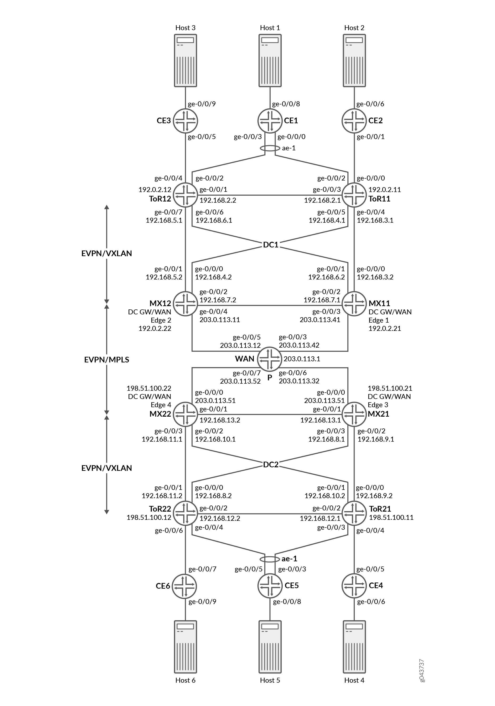
You can interconnect different data center networks running Ethernet VPN (EVPN) with Virtual extensible LAN (VXLAN) encapsulation through a WAN running MPLS-based EVPN using the logical tunnel (lt-) interface.
Figure 1 illustrates the interconnection of data center networks running EVPN with VXLAN encapsulation through a WAN running MPLS-based EVPN. For the purposes of this example, the MX Series routers acting as data center gateways and as WAN edge routers are named MX11, MX12, MX21, and MX22. The MX Series routers acting as top-of-rack (ToR) routers are named ToR11, ToR12, ToR21, and ToR22. The customer edge (CE) devices connected to the data center network 1 (DC1) are named CE1, CE2, and CE3. The customer edge (CE) devices connected to the data center network 2 (DC2) are named CE4, CE5, and CE6. The host devices connected to each CE device should be able to configure multiple host VLANs. The WAN provider router is named P.
CE devices are part of the logical system of ToR devices.
For the MX Series routers acting as data center gateways and WAN edge routers, configure the following information:
IRB interfaces, virtual gateway addresses, and loopback logical interfaces.
External BGP (EBGP) underlay connectivity between gateway and ToR routers, EVPN as the signaling protocol.
Routing policies to allow specific routes into the virtual-switch tables.
Routing instances (Layer 3 VRFs) for each virtual network, including a unique route-distinguisher, and a vrf-target value.
Virtual-switch instances (Layer 2 MAC-VRFs) for each virtual network, the VTEP source interface (always lo0.0), route distinguisher, and vrf-import policy.
EVPN protocol, encapsulation method, VNI list, and BUM traffic forwarding method for each virtual switch.
Bridge domain within each virtual switch that maps VNIDs to VLAN IDs, an IRB (Layer 3) interface, and the BUM forwarding method.
For the MX Series routers acting as top-of-rack (ToR) routers, configure the following information:
Host facing interfaces with VLANs, VLAN IDs, and loopback logical interfaces.
Link Aggregation Control Protocol (LACP)-enabled link aggregation group (LAG), Ethernet Segment ID (ESI), and
all-activemode.Multiprotocol external BGP (MP-EBGP) overlays between ToR and gateway routers using EVPN as the signaling protocol.
EVPN with VXLAN as the encapsulation method, extended-vni-list, multicast mode, and route targets for each VNI.
Vrf import policy, vtep-source-interface,
route-distinguisher, and vrf import and target information.VLANs, with VLAN IDs mapped to globally significant VNIs.
You can set the virtual gateway address as the default IPv4 or IPv6 gateway address for end hosts (virtual machines or servers).
Configuration
- Configuring ToR11
- Configuring Data Center Gateway and WAN Edge 1 Router (MX11)
- Configuring WAN Router (P)
- Configuring CE1
Configuring ToR11
Step-by-Step Procedure
The following example requires you to navigate various levels in the configuration hierarchy. For information about navigating the CLI, see Using the CLI Editor in Configuration Mode in the CLI User Guide.
Configure the MX router as ToR11:
Set the system hostname.
[edit]
user@ToR11# set system host-name ToR11
Set the number of aggregated Ethernet interfaces.
[edit]
user@ToR11# set chassis aggregated-devices ethernet device-count 1
Configure the interfaces on the ToR11 device to connect to the MX12, CE-2, CE-1, ToR12, and MX11 devices to enable underlay connectivity.
[edit]

user@ToR11# set interfaces ge-0/0/0 unit 0 description "CONNECTED TO CE-2"
user@ToR11# set interfaces ge-0/0/0 unit 0 family bridge interface-mode trunk
user@ToR11# set interfaces ge-0/0/0 unit 0 family bridge vlan-id-list 1-5
user@ToR11# set interfaces ge-0/0/2 description "CONNECTED TO CE-1"
user@ToR11# set interfaces ge-0/0/2 gigether-options 802.3ad ae0
user@ToR11# set interfaces ge-0/0/3 unit 0 description "CONNECTED TO ToR12"
user@ToR11# set interfaces ge-0/0/3 unit 0 family inet address 192.168.2.1/24
user@ToR11# set interfaces ge-0/0/4 unit 0 description "CONNECTED TO MX–11"
user@ToR11# set interfaces ge-0/0/4 unit 0 family inet address 192.168.3.1/24
user@ToR11# set interfaces ge-0/0/5 unit 0 description "CONNECTED TO MX–12"
user@ToR11# set interfaces ge-0/0/5 unit 0 family inet address 192.168.4.1/24
Configure a Link Aggregation Control Protocol (LACP)-enabled link aggregation group (LAG) interface towards the CE-1 end host device. The ESI value is globally unique across the entire EVPN domain. The
all-activeconfiguration enables ToR11 and ToR12 to forward traffic to, and from the CE devices, such that all CE links are actively used.[edit] user@ToR11# set interfaces ae0 esi 00:11:11:11:11:11:11:11:11:11 user@ToR11# set interfaces ae0 esi all-active user@ToR11# set interfaces ae0 aggregated-ether-options lacp active user@ToR11# set interfaces ae0 aggregated-ether-options lacp periodic fast user@ToR11# set interfaces ae0 aggregated-ether-options lacp system-id 11:11:11:11:11:11 user@ToR11# set interfaces ae0 unit 0 family bridge interface-mode trunk user@ToR11# set interfaces ae0 unit 0 family bridge vlan-id-list 1-5
Configure the loopback interface address and routing options.
[edit]
user@ToR11# set interfaces lo0 unit 0 family inet address 192.0.2.11/32
user@ToR11# set routing-options router-id 192.0.2.11
user@ToR11# set routing-options autonomous-system 65100
Apply the load balancing policy to the forwarding table.
[edit]
user@ToR11# set routing-options forwarding-table export evpn-pplb
Configure routing policy to accept the direct loopback address route.
[edit]
user@ToR11# set policy-options policy-statement LO term 1 from protocol direct
user@ToR11# set policy-options policy-statement LO term 1 from route-filter 192.0.2.11/32 exact
user@ToR11# set policy-options policy-statement LO term 1 then accept
Configure the NO-EXPORT community.
[edit]
user@ToR11# set policy-options community NO-EXPORT members no-advertise
user@ToR11# set policy-options community NO-EXPORT members no-export
user@ToR11# set policy-options community NO-EXPORT members no-export-subconfed
Configure the load balancing and TEST policies.
[edit]
user@ToR11# set policy-options policy-statement TEST then community add NO-EXPORT
user@ToR11# set policy-options policy-statement evpn-pplb from protocol evpn
user@ToR11# set policy-options policy-statement evpn-pplb then load-balance per-packet
Configure EVPN routing instances for each virtual network. Define the VTEP source interface, route distinguisher (used to identify and advertise EVPN routes), and
vrf-target(exports and tags all routes for that local VRF using the defined route target). Configure the EVPN protocol, encapsulation method, VNI list, and BUM traffic forwarding method. Finally, configure a bridge domain for each virtual router that maps VNIDs to VLAN IDs, and identify the BUM forwarding method.[edit] user@ToR11# set routing-instances EVPN-VXLAN-1 instance-type virtual-switch user@ToR11# set routing-instances EVPN-VXLAN-1 protocols evpn encapsulation vxlan user@ToR11# set routing-instances EVPN-VXLAN-1 protocols evpn default-gateway no-gateway-community user@ToR11# set routing-instances EVPN-VXLAN-1 protocols evpn extended-vni-list 1-5 user@ToR11# set routing-instances EVPN-VXLAN-1 vtep-source-interface lo0.0 user@ToR11# set routing-instances EVPN-VXLAN-1 bridge-domains BD-1 domain-type bridge user@ToR11# set routing-instances EVPN-VXLAN-1 bridge-domains BD-1 vlan-id 1 user@ToR11# set routing-instances EVPN-VXLAN-1 bridge-domains BD-1 routing-interface irb.1 user@ToR11# set routing-instances EVPN-VXLAN-1 bridge-domains BD-1 vxlan vni 1 user@ToR11# set routing-instances EVPN-VXLAN-1 bridge-domains BD-2 domain-type bridge user@ToR11# set routing-instances EVPN-VXLAN-1 bridge-domains BD-2 vlan-id 2 user@ToR11# set routing-instances EVPN-VXLAN-1 bridge-domains BD-2 routing-interface irb.2 user@ToR11# set routing-instances EVPN-VXLAN-1 bridge-domains BD-2 vxlan vni 2 user@ToR11# set routing-instances EVPN-VXLAN-1 bridge-domains BD-3 domain-type bridge user@ToR11# set routing-instances EVPN-VXLAN-1 bridge-domains BD-3 vlan-id 3 user@ToR11# set routing-instances EVPN-VXLAN-1 bridge-domains BD-3 routing-interface irb.3 user@ToR11# set routing-instances EVPN-VXLAN-1 bridge-domains BD-3 vxlan vni 3 user@ToR11# set routing-instances EVPN-VXLAN-1 bridge-domains BD-4 domain-type bridge user@ToR11# set routing-instances EVPN-VXLAN-1 bridge-domains BD-4 vlan-id 4 user@ToR11# set routing-instances EVPN-VXLAN-1 bridge-domains BD-4 routing-interface irb.4 user@ToR11# set routing-instances EVPN-VXLAN-1 bridge-domains BD-4 vxlan vni 4 user@ToR11# set routing-instances EVPN-VXLAN-1 bridge-domains BD-5 domain-type bridge user@ToR11# set routing-instances EVPN-VXLAN-1 bridge-domains BD-5 vlan-id 5 user@ToR11# set routing-instances EVPN-VXLAN-1 bridge-domains BD-5 routing-interface irb.5 user@ToR11# set routing-instances EVPN-VXLAN-1 bridge-domains BD-5 vxlan vni 5 user@ToR11# set routing-instances EVPN-VXLAN-1 interface ge-0/0/0.0 user@ToR11# set routing-instances EVPN-VXLAN-1 interface ae0.0 user@ToR11# set routing-instances EVPN-VXLAN-1 route-distinguisher 192.0.2.21:1 user@ToR11# set routing-instances EVPN-VXLAN-1 vrf-target target:1:1 user@ToR11# set routing-instances VRF instance-type vrf user@ToR11# set routing-instances VRF interface irb.1 user@ToR11# set routing-instances VRF interface irb.2 user@ToR11# set routing-instances VRF interface irb.3 user@ToR11# set routing-instances VRF interface irb.4 user@ToR11# set routing-instances VRF interface irb.5 user@ToR11# set routing-instances VRF route-distinguisher 1:1 user@ToR11# set routing-instances VRF vrf-target target:10:10
Configuring Data Center Gateway and WAN Edge 1 Router (MX11)
Step-by-Step Procedure
The following example requires you to navigate various levels in the configuration hierarchy. For information about navigating the CLI, see Using the CLI Editor in Configuration Mode in the CLI User Guide.
Configure an MX Series router as the data center gateway and WAN edge router and name it as MX11:
Set the system hostname.
[edit]
user@MX11# set system host-name MX11
Configure the interfaces on the MX11 router (DC GW/WAN Edge1) to enable the underlay connectivity to the MX12, ToR11, ToR12, and P devices, which is the EVPN-VXLAN part of DC1 network.
[edit]
user@MX11# set interfaces ge-0/0/0 unit 0 description "CONNECTED TO ToR11"
user@MX11# set interfaces ge-0/0/0 unit 0 family inet address 192.168.3.2/24
user@MX11# set interfaces ge-0/0/1 unit 0 description "CONNECTED TO ToR12"
user@MX11# set interfaces ge-0/0/1 unit 0 family inet address 192.168.6.2/24
user@MX11# set interfaces ge-0/0/2 unit 0 description "CONNECTED TO MX12"
user@MX11# set interfaces ge-0/0/2 unit 0 family inet address 192.168.7.1/24
user@MX11# set interfaces ge-0/0/3 unit 0 description "CONNECTED TO P"
user@MX11# set interfaces ge-0/0/3 unit 0 family inet address 203.0.113.41/24
user@MX11# set interfaces ge-0/0/3 unit 0 family mpls
Configure external BGP (EBGP) underlay connectivity between the gateway routers (MX11 and MX12) and ToR (ToR11 and ToR12).
[edit]
user@MX11# set protocols bgp group MX12 type external
user@MX11# set protocols bgp group MX12 local-address 192.168.7.1
user@MX11# set protocols bgp group MX12 export TEST
user@MX11# set protocols bgp group MX12 export LO
user@MX11# set protocols bgp group MX12 peer-as 65500
user@MX11# set protocols bgp group MX12 local-as 65400
user@MX11# set protocols bgp group MX12 neighbor 192.168.7.2 family inet unicast
user@MX11# set protocols bgp group ToR11 type external
user@MX11# set protocols bgp group ToR11 local-address 192.168.3.2
user@MX11# set protocols bgp group ToR11 import TEST
user@MX11# set protocols bgp group ToR11 export TEST
user@MX11# set protocols bgp group ToR11 export LO
user@MX11# set protocols bgp group ToR11 peer-as 65100
user@MX11# set protocols bgp group ToR11 local-as 65400
user@MX11# set protocols bgp group ToR11 neighbor 192.168.3.1 family inet unicast
user@MX11# set protocols bgp group ToR12 type external
user@MX11# set protocols bgp group ToR12 local-address 192.168.6.2
user@MX11# set protocols bgp group ToR12 export TEST
user@MX11# set protocols bgp group ToR12 export LO
user@MX11# set protocols bgp group ToR12 peer-as 65200
user@MX11# set protocols bgp group ToR12 local-as 65400
user@MX11# set protocols bgp group ToR12 neighbor 192.168.6.1 family inet unicast
Configure a multiprotocol external BGP (MP-EBGP) overlay connectivity between the gateway routers (MX11 and MX12) and ToR (ToR11 and ToR12) and set EVPN as the signaling protocol.
[edit]
user@MX11# set protocols bgp group MX12-EVPN type external
user@MX11# set protocols bgp group MX12-EVPN multihop ttl 2
user@MX11# set protocols bgp group MX12-EVPN multihop no-nexthop-change
user@MX11# set protocols bgp group MX12-EVPN local-address 192.0.2.21
user@MX11# set protocols bgp group MX12-EVPN export TEST
user@MX11# set protocols bgp group MX12-EVPN peer-as 65500
user@MX11# set protocols bgp group MX12-EVPN local-as 65400
user@MX11# set protocols bgp group MX12-EVPN neighbor 192.0.2.22 family evpn signaling
user@MX11# set protocols bgp group ToR11-EVPN type external
user@MX11# set protocols bgp group ToR11-EVPN multihop ttl 2
user@MX11# set protocols bgp group ToR11-EVPN multihop no-nexthop-change
user@MX11# set protocols bgp group ToR11-EVPN local-address 192.0.2.21
user@MX11# set protocols bgp group ToR11-EVPN export TEST
user@MX11# set protocols bgp group ToR11-EVPN peer-as 65100
user@MX11# set protocols bgp group ToR11-EVPN local-as 65400
user@MX11# set protocols bgp group ToR11-EVPN neighbor 192.0.2.11 family evpn signaling
user@MX11# set protocols bgp group ToR12-EVPN type external
user@MX11# set protocols bgp group ToR12-EVPN multihop ttl 2
user@MX11# set protocols bgp group ToR12-EVPN multihop no-nexthop-change
user@MX11# set protocols bgp group ToR12-EVPN local-address 192.0.2.21
user@MX11# set protocols bgp group ToR12-EVPN export TEST
user@MX11# set protocols bgp group ToR12-EVPN peer-as 65200
user@MX11# set protocols bgp group ToR12-EVPN local-as 65400
user@MX11# set protocols bgp group ToR12-EVPN neighbor 192.0.2.12 family evpn signaling
Configure integrated routing and bridging (IRB) interfaces that advertise the MAC and IP routes (MAC+IP type 2 routes) for hosts in the topology. The IRB configuration is the gateway for the VLANs on the hosts.
Step-by-Step Procedure
The following is the IRB gateway configuration for the VLAN-1 on MX11 (which is the host part of VLAN-1):
[edit]
user@MX11# set interfaces irb unit 1 proxy-macip-advertisement
user@MX11# set interfaces irb unit 1 virtual-gateway-esi 00:11:aa:aa:aa:aa:aa:aa:aa:aa
user@MX11# set interfaces irb unit 1 virtual-gateway-esi all-active
user@MX11# set interfaces irb unit 1 family inet address 10.11.1.12/24 virtual-gateway-address 10.11.1.10
The following is the IRB gateway configuration for the VLAN-2 on MX11 (which is the host part of VLAN-2):
[edit]
user@MX11# set interfaces irb unit 2 proxy-macip-advertisement
user@MX11# set interfaces irb unit 2 virtual-gateway-esi 00:11:bb:bb:bb:bb:bb:bb:bb:bb
user@MX11# set interfaces irb unit 2 virtual-gateway-esi all-active
user@MX11# set interfaces irb unit 2 family inet address 10.12.1.12/24 virtual-gateway-address 10.12.1.10
The following is the IRB gateway configuration for the VLAN-3 on MX11 (which is the host part of VLAN-3):
[edit]
user@MX11# set interfaces irb unit 3 proxy-macip-advertisement
user@MX11# set interfaces irb unit 3 virtual-gateway-esi 00:11:cc:cc:cc:cc:cc:cc:cc:cc
user@MX11# set interfaces irb unit 3 virtual-gateway-esi all-active
user@MX11# set interfaces irb unit 3 family inet address 10.13.1.12/24 virtual-gateway-address 10.13.1.10
The following is the IRB gateway configuration for the VLAN-4 on MX11 (which is the host part of VLAN-4):
[edit]
user@MX11# set interfaces irb unit 4 proxy-macip-advertisement
user@MX11# set interfaces irb unit 4 virtual-gateway-esi 00:11:dd:dd:dd:dd:dd:dd:dd:dd
user@MX11# set interfaces irb unit 4 virtual-gateway-esi all-active
user@MX11# set interfaces irb unit 4 family inet address 10.14.1.12/24 virtual-gateway-address 10.14.1.10
The following is the IRB gateway configuration for the VLAN-5 on MX11 (which is the host part of VLAN-5):
[edit]
user@MX11# set interfaces irb unit 5 proxy-macip-advertisement
user@MX11# set interfaces irb unit 5 virtual-gateway-esi 00:11:ee:ee:ee:ee:ee:ee:ee:ee
user@MX11# set interfaces irb unit 5 virtual-gateway-esi all-active
user@MX11# set interfaces irb unit 5 family inet address 10.15.1.12/24 virtual-gateway-address 10.15.1.10
Configure routing policy to accept the direct loopback address route.
[edit]
user@MX11# set policy-options policy-statement LO from protocol direct
user@MX11# set policy-options policy-statement LO from route-filter 192.0.2.21/32 exact
user@MX11# set policy-options policy-statement LO then accept
Configure the NO-EXPORT community.
[edit]
user@MX11# set policy-options community NO-EXPORT members no-advertise
user@MX11# set policy-options community NO-EXPORT members no-export
user@MX11# set policy-options community NO-EXPORT members no-export-subconfed
Configure the load balancing and TEST policies.
[edit]
user@MX11# set policy-options policy-statement TEST then community add NO-EXPORT
user@MX11# set policy-options policy-statement evpn-pplb from protocol evpn
user@MX11# set policy-options policy-statement evpn-pplb then load-balance per-packet
Configure an ESI value on the logical tunnel interface. Use the same ESI value on all other gateway/WAN edge routers in the DC1 network.
[edit]
user@MX11# set interfaces lt-5/1/0 esi 00:22:22:22:22:22:22:22:22:22
Configure active-active multihoming on the logical tunnel interface by including the
all-activestatement.[edit] user@MX11# set interfaces lt-5/1/0 esi all-active
Configure a pair of logical tunnel (lt-) interfaces on the MX11 gateway router to interconnect the EVPN-VXLAN instance of the data center network with the MPLS-based EVPN instance of the WAN. One logical tunnel (lt-) interface is configured as the access interface for EVPN-VXLAN and the other logical tunnel (lt-) interface is configured as the access interface for MPLS-based EVPN.
[edit]
user@MX11# set interfaces lt-5/1/0 unit 0 description TO-EVPN-VXLAN
user@MX11# set interfaces lt-5/1/0 unit 0 encapsulation ethernet-bridge
user@MX11# set interfaces lt-5/1/0 unit 0 peer-unit 1
user@MX11# set interfaces lt-5/1/0 unit 0 family bridge interface-mode trunk
user@MX11# set interfaces lt-5/1/0 unit 0 family bridge vlan-id-list 1-5
user@MX11# set interfaces lt-5/1/0 unit 1 description TO-EVPN-MPLS
user@MX11# set interfaces lt-5/1/0 unit 1 encapsulation ethernet-bridge
user@MX11# set interfaces lt-5/1/0 unit 1 peer-unit 0
user@MX11# set interfaces lt-5/1/0 unit 1 family bridge interface-mode trunk
user@MX11# set interfaces lt-5/1/0 unit 1 family bridge vlan-id-list 1-5
Configure the loopback interface address and routing options.
[edit]
user@MX11# set interfaces lo0 unit 0 family inet address 192.0.2.21/32
user@MX11# set interfaces lo0 unit 0 family mpls
user@MX11# set routing-options router-id 192.0.2.21
user@MX11# set routing-options autonomous-system 65300
Apply the load balancing policy to the forwarding table.
[edit]
user@MX11# set routing-options forwarding-table export evpn-pplb
Enable MPLS, BGP, and OSPF protocols on the core interfaces. Create MPLS LSPs and specify the address of the other gateway and WAN edge routers (MX12, P, MX21, MX22).
[edit]
user@MX11# set protocols mpls label-switched-path MX11-TO-MX12 to 192.0.2.22
user@MX11# set protocols mpls label-switched-path MX11-TO-P to 203.0.113.1
user@MX11# set protocols mpls label-switched-path MX11-TO-MX21 to 198.51.100.21
user@MX11# set protocols mpls label-switched-path MX11-TO-MX22 to 198.51.100.22
user@MX11# set protocols mpls interface all
user@MX11# set protocols mpls interface fxp0.0 disable
user@MX11# set protocols bgp local-address 192.0.2.21
user@MX11# set protocols bgp local-as 65300
user@MX11# set protocols bgp group INT type internal
user@MX11# set protocols bgp group INT local-address 192.0.2.21
user@MX11# set protocols bgp group INT family evpn signaling
user@MX11# set protocols bgp group INT export TEST
user@MX11# set protocols bgp group INT neighbor 203.0.113.1
user@MX11# set protocols ospf traffic-engineering
user@MX11# set protocols ospf area 0.0.0.0 interface ge-0/0/3.0
user@MX11# set protocols ospf area 0.0.0.0 interface lo0.0 passive
Configure EVPN-based MPLS routing instances on the MX11 router for each virtual network. Define the route distinguisher (used to identify and advertise EVPN-MPLS routes) and
vrf-target(exports and tags all routes for that local VRF using the defined route target). Configure a bridge domain for each virtual router that maps VLAN IDs.[edit] user@MX11# set routing-instances EVPN-MPLS-1 instance-type virtual-switch user@MX11# set routing-instances EVPN-MPLS-1 interface lt-5/1/0.0 user@MX11# set routing-instances EVPN-MPLS-1 route-distinguisher 192.0.2.21:100 user@MX11# set routing-instances EVPN-MPLS-1 vrf-target target:1:2 user@MX11# set routing-instances EVPN-MPLS-1 protocols evpn extended-vlan-list 1-5 user@MX11# set routing-instances EVPN-MPLS-1 protocols evpn default-gateway no-gateway-community user@MX11# set routing-instances EVPN-MPLS-1 bridge-domains BD-1 domain-type bridge user@MX11# set routing-instances EVPN-MPLS-1 bridge-domains BD-1 vlan-id 1 user@MX11# set routing-instances EVPN-MPLS-1 bridge-domains BD-2 domain-type bridge user@MX11# set routing-instances EVPN-MPLS-1 bridge-domains BD-2 vlan-id 2 user@MX11# set routing-instances EVPN-MPLS-1 bridge-domains BD-3 domain-type bridge user@MX11# set routing-instances EVPN-MPLS-1 bridge-domains BD-3 vlan-id 3 user@MX11# set routing-instances EVPN-MPLS-1 bridge-domains BD-4 domain-type bridge user@MX11# set routing-instances EVPN-MPLS-1 bridge-domains BD-4 vlan-id 4 user@MX11# set routing-instances EVPN-MPLS-1 bridge-domains BD-5 domain-type bridge user@MX11# set routing-instances EVPN-MPLS-1 bridge-domains BD-5 vlan-id 5
Configure EVPN-VXLAN routing instances on the MX11 router for each virtual network. Define the VTEP source interface, route distinguisher (used to identify and advertise EVPN routes), and
vrf-target(exports and tags all routes for that local VRF using the defined route target). Configure the EVPN protocol, encapsulation method, VNI list, and BUM traffic forwarding method. Finally, configure a bridge domain for each virtual router that maps VNIDs to VLAN IDs, and identify the BUM forwarding method.[edit] user@MX11# set routing-instances EVPN-VXLAN-1 vtep-source-interface lo0.0 user@MX11# set routing-instances EVPN-VXLAN-1 instance-type virtual-switch user@MX11# set routing-instances EVPN-VXLAN-1 interface lt-5/1/0.1 user@MX11# set routing-instances EVPN-VXLAN-1 route-distinguisher 192.0.2.21:1 user@MX11# set routing-instances EVPN-VXLAN-1 vrf-target target:1:1 user@MX11# set routing-instances EVPN-VXLAN-1 protocols evpn traceoptions file MX11-EVPN-VXLAN-1.log user@MX11# set routing-instances EVPN-VXLAN-1 protocols evpn traceoptions file size 10m user@MX11# set routing-instances EVPN-VXLAN-1 protocols evpn traceoptions flag all user@MX11# set routing-instances EVPN-VXLAN-1 protocols evpn encapsulation vxlan user@MX11# set routing-instances EVPN-VXLAN-1 protocols evpn extended-vni-list 1-5 user@MX11# set routing-instances EVPN-VXLAN-1 protocols evpn default-gateway no-gateway-community user@MX11# set routing-instances EVPN-VXLAN-1 bridge-domains BD-1 domain-type bridge user@MX11# set routing-instances EVPN-VXLAN-1 bridge-domains BD-1 vlan-id 1 user@MX11# set routing-instances EVPN-VXLAN-1 bridge-domains BD-1 routing-interface irb.1 user@MX11# set routing-instances EVPN-VXLAN-1 bridge-domains BD-1 vxlan vni 1 user@MX11# set routing-instances EVPN-VXLAN-1 bridge-domains BD-2 domain-type bridge user@MX11# set routing-instances EVPN-VXLAN-1 bridge-domains BD-2 vlan-id 2 user@MX11# set routing-instances EVPN-VXLAN-1 bridge-domains BD-2 routing-interface irb.2 user@MX11# set routing-instances EVPN-VXLAN-1 bridge-domains BD-2 vxlan vni 2 user@MX11# set routing-instances EVPN-VXLAN-1 bridge-domains BD-3 domain-type bridge user@MX11# set routing-instances EVPN-VXLAN-1 bridge-domains BD-3 vlan-id 3 user@MX11# set routing-instances EVPN-VXLAN-1 bridge-domains BD-3 routing-interface irb.3 user@MX11# set routing-instances EVPN-VXLAN-1 bridge-domains BD-3 vxlan vni 3 user@MX11# set routing-instances EVPN-VXLAN-1 bridge-domains BD-4 domain-type bridge user@MX11# set routing-instances EVPN-VXLAN-1 bridge-domains BD-4 vlan-id 4 user@MX11# set routing-instances EVPN-VXLAN-1 bridge-domains BD-4 routing-interface irb.4 user@MX11# set routing-instances EVPN-VXLAN-1 bridge-domains BD-4 vxlan vni 4 user@MX11# set routing-instances EVPN-VXLAN-1 bridge-domains BD-5 domain-type bridge user@MX11# set routing-instances EVPN-VXLAN-1 bridge-domains BD-5 vlan-id 5 user@MX11# set routing-instances EVPN-VXLAN-1 bridge-domains BD-5 routing-interface irb.5 user@MX11# set routing-instances EVPN-VXLAN-1 bridge-domains BD-5 vxlan vni 5 user@MX11# set routing-instances VRF instance-type vrf user@MX11# set routing-instances VRF interface irb.1 user@MX11# set routing-instances VRF interface irb.2 user@MX11# set routing-instances VRF interface irb.3 user@MX11# set routing-instances VRF interface
Configuring WAN Router (P)
Step-by-Step Procedure
The following example requires you to navigate various levels in the configuration hierarchy. For information about navigating the CLI, see Using the CLI Editor in Configuration Mode in the CLI User Guide.
Configure an MX Series router as the WAN edge router and name it as P:
Set the system hostname.
[edit]
user@P# set system host-name P
Configure the interfaces on the P router (WAN) to interconnect different data center networks running Ethernet VPN (EVPN) with Virtual extensible LAN (VXLAN) encapsulation through a WAN running MPLS-based EVPN.
[edit]
user@P# set interfaces ge-0/0/3 unit 0 description "CONNECTED TO MX11"
user@P# set interfaces ge-0/0/3 unit 0 family inet address 203.0.113.42/24
user@P# set interfaces ge-0/0/3 unit 0 family mpls
user@P# set interfaces ge-0/0/5 unit 0 description "CONNECTED TO MX12"
user@P# set interfaces ge-0/0/5 unit 0 family inet address 203.0.113.12/24
user@P# set interfaces ge-0/0/5 unit 0 family mpls
user@P# set interfaces ge-0/0/6 unit 0 description "CONNECTED TO MX21"
user@P# set interfaces ge-0/0/6 unit 0 family inet address 203.0.113.32/24
user@P# set interfaces ge-0/0/6 unit 0 family mpls
user@P# set interfaces ge-0/0/7 unit 0 description "CONNECTED TO MX22"
user@P# set interfaces ge-0/0/7 unit 0 family inet address 203.0.113.52/24
user@P# set interfaces ge-0/0/7 unit 0 family mpls
Configure the community.
[edit]
user@P# set policy-options community RT-CORE members target:1:2
user@P# set policy-options community RT-DC1 members target:1:1
user@P# set policy-options community RT-DC2 members target:1:3
Configure policies.
[edit]
user@P# set policy-options policy-statement BLOCK-VXLAN-ROUTES-FROM-CORE term 1 from protocol bgp
user@P# set policy-options policy-statement BLOCK-VXLAN-ROUTES-FROM-CORE term 1 from community RT-CORE
user@P# set policy-options policy-statement BLOCK-VXLAN-ROUTES-FROM-CORE term 1 then accept
user@P# set policy-options policy-statement BLOCK-VXLAN-ROUTES-FROM-CORE term 2 from protocol bgp
user@P# set policy-options policy-statement BLOCK-VXLAN-ROUTES-FROM-CORE term 2 from community RT-DC1
user@P# set policy-options policy-statement BLOCK-VXLAN-ROUTES-FROM-CORE term 2 then reject
user@P# set policy-options policy-statement BLOCK-VXLAN-ROUTES-FROM-CORE term 3 from protocol bgp
user@P# set policy-options policy-statement BLOCK-VXLAN-ROUTES-FROM-CORE term 3 from community RT-DC2
user@P# set policy-options policy-statement BLOCK-VXLAN-ROUTES-FROM-CORE term 3 then reject
Configure the loopback interface address and routing options.
[edit]
user@P# interfaces lo0 unit 86 family inet address 203.0.113.1/32
user@P# interfaces lo0 unit 86 family mpls
user@P# routing-options router-id 203.0.113.1
user@P# routing-options autonomous-system 65300
Enable MPLS, BGP, and OSPF protocols on the core interfaces. Create MPLS LSPs between P and other gateway and WAN edge routers (MX11, MX12, P, MX22).
[edit]
user@P# set protocols mpls label-switched-path P-TO-MX11 from 203.0.113.1
user@P# set protocols mpls label-switched-path P-TO-MX11 to 192.0.2.21
user@P# set protocols mpls label-switched-path P-TO-MX12 to 192.0.2.22
user@P# set protocols mpls label-switched-path P-TO-MX21 to 198.51.100.21
user@P# set protocols mpls label-switched-path P-TO-MX22 to 198.51.100.22
user@P# set protocols mpls interface all
user@P# set protocols bgp group INT type internal
user@P# set protocols bgp group INT import BLOCK-VXLAN-ROUTES-FROM-CORE
user@P# set protocols bgp group INT family evpn signaling
user@P# set protocols bgp group INT cluster 203.0.113.1
user@P# set protocols bgp group INT neighbor 192.0.2.21
user@P# set protocols bgp group INT neighbor 192.0.2.22
user@P# set protocols bgp group INT neighbor 198.51.100.21
user@P# set protocols bgp group INT neighbor 198.51.100.22
user@P# set protocols bgp local-address 203.0.113.1
user@P# set protocols bgp local-as 65300
user@P# set protocols ospf traffic-engineering
user@P# set protocols ospf area 0.0.0.0 interface all
user@P# set protocols ospf area 0.0.0.0 interface lo0.86
Configuring CE1
Step-by-Step Procedure
The following example requires you to navigate various levels in the configuration hierarchy. For information about navigating the CLI, see Using the CLI Editor in Configuration Mode in the CLI User Guide.
Configure the MX router CE1:
Set the system hostname.
[edit]
user@CE1# set system host-name CE1
Configure the interfaces on the CE1 device to connect to the host and TOR12. Enables forwarding traffic between host and TOR12.
[edit]
user@CE1# set interfaces ge-0/0/8 unit 0 description "CONNECTED TO Host 1"
user@CE1# set interfaces ge-0/0/8 unit 0 family bridge interface-mode trunk
user@CE1# set interfaces ge-0/0/8 unit 0 family bridge vlan-id-list 1-5
user@CE1# set interfaces ae1 unit 0 description "CONNECTED TO ToR12"
user@CE1# set interfaces ae1 unit 0 family bridge interface-mode trunk
user@CE1# set interfaces ae1 unit 0 family bridge vlan-id-list 1-5
Define bridge domains and associate it with a VLAN ID.
[edit]
user@CE1# set bridge-domains BD-1 domain-type bridge
user@CE1# set bridge-domains BD-1 vlan-id 1
user@CE1# set bridge-domains BD-2 domain-type bridge
user@CE1# set bridge-domains BD-2 vlan-id 2
user@CE1# set bridge-domains BD-3 domain-type bridge
user@CE1# set bridge-domains BD-3 vlan-id 3
user@CE1# set bridge-domains BD-4 domain-type bridge
user@CE1# set bridge-domains BD-4 vlan-id 4
user@CE1# set bridge-domains BD-5 domain-type bridge
user@CE1# set bridge-domains BD-5 vlan-id 5
Verification
After you configure both the underlay and EVPN overlay we recommend that you verify that the configurations work as you intended.
- Verify EVPN-VXLAN and EVPN-MPLS EVI stitching using Logical Tunnel interface
- Verify flooding in bridge domains
- Verify MAC learning
- Verify MAC Address Forwarding Table
Verify EVPN-VXLAN and EVPN-MPLS EVI stitching using Logical Tunnel interface
Purpose
Confirm the EVPN-VXLAN and EVPN-MPLS EVPN instances (EVIs) are configured for stitching using logical tunnel interfaces.
Action
On any gateway device, issue the show routing-instances
evpn-vxlan-instance and the show
routing-instances evpn-mpls-instance
commands to see the logical tunnel interfaces assigned to the respective
EVIs. Issue the show interfaces lt-interface command to
verify the EVIs are stitched using the assigned LT interface.
user@MX11> show routing-instances EVPN-VXLAN-1
…
interface lt-5/1/0.1;
route-distinguisher 192.0.2.21:1;
vrf-target target:1:1;
user@MX11> show routing-instances EVPN-MPLS-1
…
interface lt-5/1/0.0;
route-distinguisher 192.0.2.21:100;
vrf-target target:1:2;
user@MX11> show interfaces lt-5/1/0
esi {
    00:22:22:22:22:22:22:22:22:22;
    all-active;
}
unit 0 {
    description TO-EVPN-VXLAN;
    encapsulation ethernet-bridge;
    peer-unit 1;
    family bridge {
        interface-mode trunk;
        vlan-id-list 1-5;
    }
}
unit 1 {
    description TO-EVPN-MPLS;
    encapsulation ethernet-bridge;
    peer-unit 0;
    family bridge {
        interface-mode trunk;
        vlan-id-list 1-5;
    }
}
Meaning
The EVPN-VXLAN-1 and the EVPN-MPLS-1 EVIs are stitched using lt-5/1/0 interface.
Verify flooding in bridge domains
Purpose
Verify bridge domain flood information for both EVPN-MPLS and EVPN-VXLAN instances any gateway device.
Action
On any gateway device (MX11), issue the show bridge flood extensive
instance instance-name command.
user@MX11> show bridge flood extensive instance EVPN-MPLS-1
Name: EVPN-MPLS-1
CEs: 1
VEs: 15
Bridging domain: BD-1
  EVPN extended: Yes
  Flood route prefix: 0x3001a/51
  Flood route type: FLOOD_GRP_COMP_NH
  Flood route owner: __ves__
  Flood group name: __ves__
  Flood group index: 0
  Nexthop type: comp
  Nexthop index: 779
    Flooding to:
    Name             Type          NhType          Index
    __all_ces__      Group          comp            759
        Composition: split-horizon
        Flooding to:
        Name             Type          NhType          Index
        lt-5/1/0.0       MH-CE          ucst            736
                         ESI: 00:22:22:22:22:22:22:22:22:22

  Flood route prefix: 0x30010/51
  Flood route type: FLOOD_GRP_COMP_NH
  Flood route owner: __all_ces__
  Flood group name: __all_ces__
  Flood group index: 1
  Nexthop type: comp
  Nexthop index: 812
    Flooding to:
    Name             Type          NhType          Index
    __all_ces__      Group          comp            759
        Composition: split-horizon
        Flooding to:
        Name             Type          NhType          Index
        lt-5/1/0.0       MH-CE          ucst            736
                         ESI: 00:22:22:22:22:22:22:22:22:22
    Flooding to:
    Name             Type          NhType          Index
    __ves__          Group          comp            763
        Composition: flood-to-all
    Component flood-nh(s) (for flooding to EVPN core):
    Index         Peer             NH-Type
    891           192.0.2.22       comp (IM/SH)
    892           198.51.100.21       comp (IM/SH)
    746           198.51.100.22    comp (IM/SH)
user@MX11> show bridge flood extensive instance EVPN-VXLAN-1Name: EVPN-VXLAN-1
Name: EVPN-VXLAN-1
CEs: 1
VEs: 3
Bridging domain: BD-1
  Flood route prefix: 0x3000f/51
  Flood route type: FLOOD_GRP_COMP_NH
  Flood route owner: __ves__
  Flood group name: __ves__
  Flood group index: 0
  Nexthop type: comp
  Nexthop index: 845
    Flooding to:
    Name             Type          NhType          Index
    __all_ces__      Group          comp            797
        Composition: split-horizon
        Flooding to:
        Name             Type          NhType          Index
        lt-5/1/0.0       CE             ucst            751

  Flood route prefix: 0x30015/51
  Flood route type: FLOOD_GRP_COMP_NH
  Flood route owner: __all_ces__
  Flood group name: __all_ces__
  Flood group index: 1
  Nexthop type: comp
  Nexthop index: 842
    Flooding to:
    Name             Type          NhType          Index
    __all_ces__      Group          comp            797
        Composition: split-horizon
        Flooding to:
        Name             Type          NhType          Index
        lt-5/1/0.0       CE             ucst            751
    Flooding to:
    Name             Type          NhType          Index
    __ves__          Group          comp            700
        Composition: flood-to-all
        Flooding to:
        Name             Type          NhType          Index          RVTEP-IP
        vtep.32769       CORE_FACING    venh            687           192.0.2.11
        vtep.32770       CORE_FACING    venh            729           192.0.2.12
        vtep.32771       CORE_FACING    venh            748           192.0.2.22
Meaning
The output shows that EVPN-MPLS-1 is actively participating in BUM traffic flooding for the associated bridge domains. It uses composite next-hop groups to flood traffic to other gateway devices in the MPLS core, which is MX12 (192.0.2.22), MX21 (198.51.100.21), and MX22 (198.51.100.22). Meanwhile, the EVPN-MPLS instance EVPN-MPLS-1 has bridge domains configured for EVPN extension with active endpoints to neighboring gateway devices.
Verify MAC learning
Purpose
Verify the MAC learning between gateway devices.
Action
On any leaf device (TOR11), issue the show evpn database instance
routing-instance-name l2-domain-id 1
command to verify the learned MAC addresses.
user@TOR11> show evpn database instance EVPN-VXLAN-1 l2-domain-id 1
 Instance: EVPN-VXLAN-1
VLAN  DomainId  MAC address        Active source                  Timestamp        IP address
     1          00:00:5e:00:01:01  00:11:aa:aa:aa:aa:aa:aa:aa:aa  Jul 30 01:02:11  10.11.1.10
     1          2c:6b:f5:c2:ff:f0   DRP              vtep.32769             Jul 30 01:02:11  192.0.2.21
Meaning
The host MAC/IP binding is learned from a remote VTEP (192.0.2.21 which is MX11), showing active host participation in the EVPN fabric.
Verify MAC Address Forwarding Table
Purpose
Verify MAC learning and flooding behavior in the bridging environment.
Action
On any gateway device, issue the show bridge mac-table
mac-address instance
evpn-instance.
user@MX11> show bridge mac-table 2c:6b:f5:c2:ff:f0 instance EVPN-VXLAN-1
MAC flags       (S -static MAC, D -dynamic MAC, L -locally learned, C -Control MAC
    O -OVSDB MAC, SE -Statistics enabled, NM -Non configured MAC, R -Remote PE MAC, P -Pinned MAC)

Routing instance : EVPN-VXLAN-1
 Bridging domain : BD-1, VLAN : 1
   MAC                 MAC      GBP     Logical                Active
   address             flags    TAG     interface              source
   2c:6b:f5:c2:ff:f0   DR              lt-5/1/0.1             192.0.2.22
user@MX11> show bridge mac-table 2c:6b:f5:c2:ff:f0 instance EVPN-MPLS-1
MAC flags       (S -static MAC, D -dynamic MAC, L -locally learned, C -Control MAC
    O -OVSDB MAC, SE -Statistics enabled, NM -Non configured MAC, R -Remote PE MAC, P -Pinned MAC)

Routing instance : EVPN-MPLS-1
 Bridging domain : BD-1, VLAN : 1
   MAC                 MAC      GBP     Logical                NH             RTR
   address             flags    TAG     interface             Index          ID
   2c:6b:f5:c2:ff:f0   DC                                           1048581    1048581
Meaning
For the EVPN-VXLAN-1 instance, the MAC address 2c:6b:f5:c2:ff:f0 is dynamically learned (D flag) and associated with Bridge Domain BD-1 (VLAN 1) in the EVPN instance EVPN-VXLAN-1. It was learned from a lt-5/1/0.1 logical tunnel interface, with the remote source IP 192.0.2.22 (MX12), indicating that this MAC belongs to a host connected to a remote device in the EVPN fabric.
For the EVPN-MPLS-1 instance, the MAC address 2c:6b:f5:c2:ff:f0 is present in Bridge Domain BD-1 (VLAN 1) under the EVPN instance EVPN-MPLS-1. It is marked with flags D (Dynamically learned) and C (Control MAC), indicating that it was learned via the EVPN control plane rather than data plane snooping. The MAC is associated with a next-hop index 1048581, which maps to a remote router, confirming that this MAC belongs to a host reachable via EVPN/MPLS from a remote site.
Appendix 1: Set Commands on All Devices
Set command output on all devices.
To quickly configure this example, copy the following commands, paste them into a
text file, remove any line breaks, change any details necessary to match your
network configuration, and then copy and paste the commands into the CLI at the
[edit] hierarchy level.
ToR11
set system host-name ToR11
set chassis aggregated-devices ethernet device-count 1
set interfaces ge-0/0/0 unit 0 description "CONNECTED TO CE-2"
set interfaces ge-0/0/0 unit 0 family bridge interface-mode trunk
set interfaces ge-0/0/0 unit 0 family bridge vlan-id-list 1-5
set interfaces ge-0/0/2 description "CONNECTED TO CE-1"
set interfaces ge-0/0/2 gigether-options 802.3ad ae0
set interfaces ge-0/0/3 unit 0 description "CONNECTED TO ToR12"
set interfaces ge-0/0/3 unit 0 family inet address 192.168.2.1/24
set interfaces ge-0/0/4 unit 0 description "CONNECTED TO MX–11"
set interfaces ge-0/0/4 unit 0 family inet address 192.168.3.1/24
set interfaces ge-0/0/5 unit 0 description "CONNECTED TO MX–12"
set interfaces ge-0/0/5 unit 0 family inet address 192.168.4.1/24
set interfaces ae0 esi 00:11:11:11:11:11:11:11:11:11
set interfaces ae0 esi all-active
set interfaces ae0 aggregated-ether-options lacp active
set interfaces ae0 aggregated-ether-options lacp periodic fast
set interfaces ae0 aggregated-ether-options lacp system-id 11:11:11:11:11:11
set interfaces ae0 unit 0 family bridge interface-mode trunk
set interfaces ae0 unit 0 family bridge vlan-id-list 1-5
set interfaces lo0 unit 0 family inet address 192.0.2.11/32
set policy-options policy-statement LO term 1 from protocol direct
set policy-options policy-statement LO term 1 from route-filter 192.0.2.11/32 exact
set policy-options policy-statement LO term 1 then accept
set policy-options policy-statement TEST then community add NO-EXPORT
set policy-options policy-statement evpn-pplb from protocol evpn
set policy-options policy-statement evpn-pplb then load-balance per-packet
set policy-options community NO-EXPORT members no-advertise
set policy-options community NO-EXPORT members no-export
set policy-options community NO-EXPORT members no-export-subconfed
set routing-instances EVPN-VXLAN-1 instance-type virtual-switch
set routing-instances EVPN-VXLAN-1 protocols evpn encapsulation vxlan
set routing-instances EVPN-VXLAN-1 protocols evpn default-gateway no-gateway-community
set routing-instances EVPN-VXLAN-1 protocols evpn extended-vni-list 1-5
set routing-instances EVPN-VXLAN-1 vtep-source-interface lo0.0
set routing-instances EVPN-VXLAN-1 bridge-domains BD-1 domain-type bridge
set routing-instances EVPN-VXLAN-1 bridge-domains BD-1 vlan-id 1
set routing-instances EVPN-VXLAN-1 bridge-domains BD-1 routing-interface irb.1
set routing-instances EVPN-VXLAN-1 bridge-domains BD-1 vxlan vni 1
set routing-instances EVPN-VXLAN-1 bridge-domains BD-2 domain-type bridge
set routing-instances EVPN-VXLAN-1 bridge-domains BD-2 vlan-id 2
set routing-instances EVPN-VXLAN-1 bridge-domains BD-2 routing-interface irb.2
set routing-instances EVPN-VXLAN-1 bridge-domains BD-2 vxlan vni 2
set routing-instances EVPN-VXLAN-1 bridge-domains BD-3 domain-type bridge
set routing-instances EVPN-VXLAN-1 bridge-domains BD-3 vlan-id 3
set routing-instances EVPN-VXLAN-1 bridge-domains BD-3 routing-interface irb.3
set routing-instances EVPN-VXLAN-1 bridge-domains BD-3 vxlan vni 3
set routing-instances EVPN-VXLAN-1 bridge-domains BD-4 domain-type bridge
set routing-instances EVPN-VXLAN-1 bridge-domains BD-4 vlan-id 4
set routing-instances EVPN-VXLAN-1 bridge-domains BD-4 routing-interface irb.4
set routing-instances EVPN-VXLAN-1 bridge-domains BD-4 vxlan vni 4
set routing-instances EVPN-VXLAN-1 bridge-domains BD-5 domain-type bridge
set routing-instances EVPN-VXLAN-1 bridge-domains BD-5 vlan-id 5
set routing-instances EVPN-VXLAN-1 bridge-domains BD-5 routing-interface irb.5
set routing-instances EVPN-VXLAN-1 bridge-domains BD-5 vxlan vni 5
set routing-instances EVPN-VXLAN-1 interface ge-0/0/0.0
set routing-instances EVPN-VXLAN-1 interface ae0.0
set routing-instances EVPN-VXLAN-1 route-distinguisher 192.0.2.21:1
set routing-instances EVPN-VXLAN-1 vrf-target target:1:1
set routing-instances VRF instance-type vrf
set routing-instances VRF interface irb.1
set routing-instances VRF interface irb.2
set routing-instances VRF interface irb.3
set routing-instances VRF interface irb.4
set routing-instances VRF interface irb.5
set routing-instances VRF route-distinguisher 1:1
set routing-instances VRF vrf-target target:10:10
set routing-options router-id 192.0.2.11
set routing-options autonomous-system 65100
set routing-options forwarding-table export evpn-pplb
ToR12
set system host-name ToR12

set chassis aggregated-devices ethernet device-count 2
set interfaces ge-0/0/0 description "CONNECTED TO ToR11"
set interfaces ge-0/0/0 gigether-options 802.3ad ae1
set interfaces ge-0/0/1 unit 0 description "CONNECTED TO ToR11"
set interfaces ge-0/0/1 unit 0 family inet address 192.168.2.2/24
set interfaces ge-0/0/2 description "CONNECTED TO CE-1"
set interfaces ge-0/0/2 gigether-options 802.3ad ae0
set interfaces ge-0/0/3 description "CONNECTED TO ToR12"
set interfaces ge-0/0/3 gigether-options 802.3ad ae1
set interfaces ge-0/0/4 unit 0 description "CONNECTED TO CE-3"
set interfaces ge-0/0/4 unit 0 family bridge interface-mode trunk
set interfaces ge-0/0/4 unit 0 family bridge vlan-id-list 1-5
set interfaces ge-0/0/6 unit 0 description "CONNECTED TO MX11"
set interfaces ge-0/0/6 unit 0 family inet address 192.168.6.1/24
set interfaces ge-0/0/7 unit 0 description "CONNECTED TO MX12"
set interfaces ge-0/0/7 unit 0 family inet address 192.168.5.1/24
set interfaces ae0 esi 00:11:11:11:11:11:11:11:11:11
set interfaces ae0 esi all-active
set interfaces ae0 aggregated-ether-options lacp system-id 11:11:11:11:11:11
set interfaces ae0 unit 0 family bridge interface-mode trunk
set interfaces ae0 unit 0 family bridge vlan-id-list 1-5
set interfaces ae1 aggregated-ether-options lacp active
set interfaces ae1 aggregated-ether-options lacp periodic fast
set interfaces lo0 unit 0 family inet address 192.0.2.12/32
set policy-options policy-statement LO term 1 from protocol direct
set policy-options policy-statement LO term 1 from route-filter 192.0.2.12/32 exact
set policy-options policy-statement LO term 1 then accept
set policy-options policy-statement TEST then community add NO-EXPORT
set policy-options policy-statement evpn-pplb from protocol evpn
set policy-options policy-statement evpn-pplb then load-balance per-packet
set policy-options community NO-EXPORT members no-advertise
set policy-options community NO-EXPORT members no-export
set policy-options community NO-EXPORT members no-export-subconfed
set routing-instances EVPN-VXLAN-1 instance-type virtual-switch
set routing-instances EVPN-VXLAN-1 protocols evpn encapsulation vxlan
set routing-instances EVPN-VXLAN-1 protocols evpn extended-vni-list 1-5
set routing-instances EVPN-VXLAN-1 vtep-source-interface lo0.0
set routing-instances EVPN-VXLAN-1 bridge-domains BD-1 domain-type bridge
set routing-instances EVPN-VXLAN-1 bridge-domains BD-1 vlan-id 1
set routing-instances EVPN-VXLAN-1 bridge-domains BD-1 vxlan vni 1
set routing-instances EVPN-VXLAN-1 bridge-domains BD-2 domain-type bridge
set routing-instances EVPN-VXLAN-1 bridge-domains BD-2 vlan-id 2
set routing-instances EVPN-VXLAN-1 bridge-domains BD-2 vxlan vni 2
set routing-instances EVPN-VXLAN-1 bridge-domains BD-3 domain-type bridge
set routing-instances EVPN-VXLAN-1 bridge-domains BD-3 vlan-id 3
set routing-instances EVPN-VXLAN-1 bridge-domains BD-3 vxlan vni 3
set routing-instances EVPN-VXLAN-1 bridge-domains BD-4 domain-type bridge
set routing-instances EVPN-VXLAN-1 bridge-domains BD-4 vlan-id 4
set routing-instances EVPN-VXLAN-1 bridge-domains BD-4 vxlan vni 4
set routing-instances EVPN-VXLAN-1 bridge-domains BD-5 domain-type bridge
set routing-instances EVPN-VXLAN-1 bridge-domains BD-5 vlan-id 5
set routing-instances EVPN-VXLAN-1 bridge-domains BD-5 vxlan vni 5
set routing-instances EVPN-VXLAN-1 interface ge-0/0/4.0
set routing-instances EVPN-VXLAN-1 interface ae0.0
set routing-instances EVPN-VXLAN-1 route-distinguisher 192.0.2.12:1
set routing-instances EVPN-VXLAN-1 vrf-target target:1:1
set routing-options router-id 192.0.2.12
set routing-options autonomous-system 65200
set routing-options forwarding-table export evpn-pplb
set protocols bgp group MX11 type external
set protocols bgp group MX11 local-address 192.168.6.1
set protocols bgp group MX11 export LO
set protocols bgp group MX11 export TEST
set protocols bgp group MX11 peer-as 65400
set protocols bgp group MX11 local-as 65200
set protocols bgp group MX11 neighbor 192.168.6.2 family inet unicast
set protocols bgp group MX12 type external
set protocols bgp group MX12 local-address 192.168.5.1
set protocols bgp group MX12 export LO
set protocols bgp group MX12 export TEST
set protocols bgp group MX12 peer-as 65500
set protocols bgp group MX12 local-as 65200
set protocols bgp group MX12 neighbor 192.168.5.2 family inet unicast
set protocols bgp group ToR11 type external
set protocols bgp group ToR11 local-address 192.168.2.2
set protocols bgp group ToR11 export LO
set protocols bgp group ToR11 export TEST
set protocols bgp group ToR11 peer-as 65100
set protocols bgp group ToR11 local-as 65200
set protocols bgp group ToR11 neighbor 192.168.2.1 family inet unicast
set protocols bgp group MX11-EVPN type external
set protocols bgp group MX11-EVPN multihop ttl 2
set protocols bgp group MX11-EVPN multihop no-nexthop-change
set protocols bgp group MX11-EVPN local-address 192.0.2.12
set protocols bgp group MX11-EVPN export TEST
set protocols bgp group MX11-EVPN peer-as 65400
set protocols bgp group MX11-EVPN local-as 65200
set protocols bgp group MX11-EVPN neighbor 192.0.2.21 family evpn signaling
set protocols bgp group MX12-EVPN type external
set protocols bgp group MX12-EVPN multihop ttl 2
set protocols bgp group MX12-EVPN multihop no-nexthop-change
set protocols bgp group MX12-EVPN local-address 192.0.2.12
set protocols bgp group MX12-EVPN export TEST
set protocols bgp group MX12-EVPN peer-as 65500
set protocols bgp group MX12-EVPN local-as 65200
set protocols bgp group MX12-EVPN neighbor 192.0.2.22 family evpn signaling
set protocols bgp group ToR11-EVPN type external
set protocols bgp group ToR11-EVPN multihop ttl 2
set protocols bgp group ToR11-EVPN multihop no-nexthop-change
set protocols bgp group ToR11-EVPN local-address 192.0.2.12
set protocols bgp group ToR11-EVPN export TEST
set protocols bgp group ToR11-EVPN peer-as 65100
set protocols bgp group ToR11-EVPN local-as 65200
set protocols bgp group ToR11-EVPN neighbor 192.0.2.11 family evpn signaling
set protocols bgp group ToR12-EVPN export TEST
set protocols bgp local-as 65200
Data Center Gateway and WAN Edge 1 Router (MX11)
set system host-name MX11
set interfaces ge-0/0/0 unit 0 description "CONNECTED TO ToR11"
set interfaces ge-0/0/0 unit 0 family inet address 192.168.3.2/24
set interfaces ge-0/0/1 unit 0 description "CONNECTED TO ToR12"
set interfaces ge-0/0/1 unit 0 family inet address 192.168.6.2/24
set interfaces ge-0/0/2 unit 0 description "CONNECTED TO MX12"
set interfaces ge-0/0/2 unit 0 family inet address 192.168.7.1/24
set interfaces ge-0/0/3 unit 0 description "CONNECTED TO P"
set interfaces ge-0/0/3 unit 0 family inet address 203.0.113.41/24
set interfaces ge-0/0/3 unit 0 family mpls
set interfaces lt-5/1/0 esi 00:22:22:22:22:22:22:22:22:22
set interfaces lt-5/1/0 esi 00:22:22:22:22:22:22:22:22:22
set interfaces lt-5/1/0 esi all-active
set interfaces lt-5/1/0 unit 0 description TO-EVPN-VXLAN
set interfaces lt-5/1/0 unit 0 encapsulation ethernet-bridge
set interfaces lt-5/1/0 unit 0 peer-unit 1
set interfaces lt-5/1/0 unit 0 family bridge interface-mode trunk
set interfaces lt-5/1/0 unit 0 family bridge vlan-id-list 1-5
set interfaces lt-5/1/0 unit 1 description TO-EVPN-MPLS
set interfaces lt-5/1/0 unit 1 encapsulation ethernet-bridge
set interfaces lt-5/1/0 unit 1 peer-unit 0
set interfaces lt-5/1/0 unit 1 family bridge interface-mode trunk
set interfaces lt-5/1/0 unit 1 family bridge vlan-id-list 1-5set interfaces irb unit 1 proxy-macip-advertisement
set interfaces irb unit 1 virtual-gateway-esi 00:11:aa:aa:aa:aa:aa:aa:aa:aa
set interfaces irb unit 1 virtual-gateway-esi all-active
set interfaces irb unit 1 family inet address 10.11.1.12/24 virtual-gateway-address 10.11.1.10
set interfaces irb unit 2 proxy-macip-advertisement
set interfaces irb unit 2 virtual-gateway-esi 00:11:bb:bb:bb:bb:bb:bb:bb:bb
set interfaces irb unit 2 virtual-gateway-esi all-active
set interfaces irb unit 2 family inet address 10.12.1.12/24 virtual-gateway-address 10.12.1.10
set interfaces irb unit 3 proxy-macip-advertisement
set interfaces irb unit 3 virtual-gateway-esi 00:11:cc:cc:cc:cc:cc:cc:cc:cc
set interfaces irb unit 3 virtual-gateway-esi all-active
set interfaces irb unit 3 family inet address 10.13.1.12/24 virtual-gateway-address 10.13.1.10
set interfaces irb unit 4 proxy-macip-advertisement
set interfaces irb unit 4 virtual-gateway-esi 00:11:dd:dd:dd:dd:dd:dd:dd:dd
set interfaces irb unit 4 virtual-gateway-esi all-active
set interfaces irb unit 4 family inet address 10.14.1.12/24 virtual-gateway-address 10.14.1.10
set interfaces irb unit 5 proxy-macip-advertisement
set interfaces irb unit 5 virtual-gateway-esi 00:11:ee:ee:ee:ee:ee:ee:ee:ee
set interfaces irb unit 5 virtual-gateway-esi all-active
set interfaces irb unit 5 family inet address 10.15.1.12/24 virtual-gateway-address 10.15.1.10
set interfaces lo0 unit 0 family inet address 192.0.2.21/32
set interfaces lo0 unit 0 family mpls
set policy-options policy-statement LO from protocol direct
set policy-options policy-statement LO from route-filter 192.0.2.21/32 exact
set policy-options policy-statement LO then accept
set policy-options policy-statement TEST then community add NO-EXPORT
set policy-options policy-statement evpn-pplb from protocol evpn
set policy-options policy-statement evpn-pplb then load-balance per-packet
set policy-options community NO-EXPORT members no-advertise
set policy-options community NO-EXPORT members no-export
set policy-options community NO-EXPORT members no-export-subconfed
set routing-instances EVPN-MPLS-1 instance-type virtual-switch
set routing-instances EVPN-MPLS-1 protocols evpn default-gateway no-gateway-community
set routing-instances EVPN-MPLS-1 protocols evpn extended-vlan-list 1-5
set routing-instances EVPN-MPLS-1 bridge-domains BD-1 domain-type bridge
set routing-instances EVPN-MPLS-1 bridge-domains BD-1 vlan-id 1
set routing-instances EVPN-MPLS-1 bridge-domains BD-2 domain-type bridge
set routing-instances EVPN-MPLS-1 bridge-domains BD-2 vlan-id 2
set routing-instances EVPN-MPLS-1 bridge-domains BD-3 domain-type bridge
set routing-instances EVPN-MPLS-1 bridge-domains BD-3 vlan-id 3
set routing-instances EVPN-MPLS-1 bridge-domains BD-4 domain-type bridge
set routing-instances EVPN-MPLS-1 bridge-domains BD-4 vlan-id 4
set routing-instances EVPN-MPLS-1 bridge-domains BD-5 domain-type bridge
set routing-instances EVPN-MPLS-1 bridge-domains BD-5 vlan-id 5
set routing-instances EVPN-MPLS-1 interface lt-5/1/0.0
set routing-instances EVPN-MPLS-1 route-distinguisher 192.0.2.21:100
set routing-instances EVPN-MPLS-1 vrf-target target:1:2
set routing-instances EVPN-VXLAN-1 instance-type virtual-switch
set routing-instances EVPN-VXLAN-1 protocols evpn encapsulation vxlan
set routing-instances EVPN-VXLAN-1 protocols evpn default-gateway no-gateway-community
set routing-instances EVPN-VXLAN-1 protocols evpn extended-vni-list 1-5
set routing-instances EVPN-VXLAN-1 vtep-source-interface lo0.0
set routing-instances EVPN-VXLAN-1 bridge-domains BD-1 domain-type bridge
set routing-instances EVPN-VXLAN-1 bridge-domains BD-1 vlan-id 1
set routing-instances EVPN-VXLAN-1 bridge-domains BD-1 routing-interface irb.1
set routing-instances EVPN-VXLAN-1 bridge-domains BD-1 vxlan vni 1
set routing-instances EVPN-VXLAN-1 bridge-domains BD-2 domain-type bridge
set routing-instances EVPN-VXLAN-1 bridge-domains BD-2 vlan-id 2
set routing-instances EVPN-VXLAN-1 bridge-domains BD-2 routing-interface irb.2
set routing-instances EVPN-VXLAN-1 bridge-domains BD-2 vxlan vni 2
set routing-instances EVPN-VXLAN-1 bridge-domains BD-3 domain-type bridge
set routing-instances EVPN-VXLAN-1 bridge-domains BD-3 vlan-id 3
set routing-instances EVPN-VXLAN-1 bridge-domains BD-3 routing-interface irb.3
set routing-instances EVPN-VXLAN-1 bridge-domains BD-3 vxlan vni 3
set routing-instances EVPN-VXLAN-1 bridge-domains BD-4 domain-type bridge
set routing-instances EVPN-VXLAN-1 bridge-domains BD-4 vlan-id 4
set routing-instances EVPN-VXLAN-1 bridge-domains BD-4 routing-interface irb.4
set routing-instances EVPN-VXLAN-1 bridge-domains BD-4 vxlan vni 4
set routing-instances EVPN-VXLAN-1 bridge-domains BD-5 domain-type bridge
set routing-instances EVPN-VXLAN-1 bridge-domains BD-5 vlan-id 5
set routing-instances EVPN-VXLAN-1 bridge-domains BD-5 routing-interface irb.5
set routing-instances EVPN-VXLAN-1 bridge-domains BD-5 vxlan vni 5
set routing-instances EVPN-VXLAN-1 interface lt-5/1/0.1
set routing-instances EVPN-VXLAN-1 route-distinguisher 192.0.2.21:1
set routing-instances EVPN-VXLAN-1 vrf-target target:1:1
set routing-instances VRF instance-type vrf
set routing-instances VRF interface irb.1
set routing-instances VRF interface irb.2
set routing-instances VRF interface irb.3
set routing-instances VRF interface
set protocols bgp group INT type internal
set protocols bgp group INT local-address 192.0.2.21
set protocols bgp group INT family evpn signaling
set protocols bgp group INT export TEST
set protocols bgp group INT neighbor 203.0.113.1
set protocols bgp group MX12 type external
set protocols bgp group MX12 local-address 192.168.7.1
set protocols bgp group MX12 export TEST
set protocols bgp group MX12 export LO
set protocols bgp group MX12 peer-as 65500
set protocols bgp group MX12 local-as 65400
set protocols bgp group MX12 neighbor 192.168.7.2 family inet unicast
set protocols bgp group ToR11 type external
set protocols bgp group ToR11 local-address 192.168.3.2
set protocols bgp group ToR11 import TEST
set protocols bgp group ToR11 export TEST
set protocols bgp group ToR11 export LO
set protocols bgp group ToR11 peer-as 65100
set protocols bgp group ToR11 local-as 65400
set protocols bgp group ToR11 neighbor 192.168.3.1 family inet unicast
set protocols bgp group ToR12 type external
set protocols bgp group ToR12 local-address 192.168.6.2
set protocols bgp group ToR12 export TEST
set protocols bgp group ToR12 export LO
set protocols bgp group ToR12 peer-as 65200
set protocols bgp group ToR12 local-as 65400
set protocols bgp group ToR12 neighbor 192.168.6.1 family inet unicast
set protocols bgp group MX12-EVPN type external
set protocols bgp group MX12-EVPN multihop ttl 2
set protocols bgp group MX12-EVPN multihop no-nexthop-change
set protocols bgp group MX12-EVPN local-address 192.0.2.21
set protocols bgp group MX12-EVPN export TEST
set protocols bgp group MX12-EVPN peer-as 65500
set protocols bgp group MX12-EVPN local-as 65400
set protocols bgp group MX12-EVPN neighbor 192.0.2.22 family evpn signaling
set protocols bgp group ToR11-EVPN type external
set protocols bgp group ToR11-EVPN multihop ttl 2
set protocols bgp group ToR11-EVPN multihop no-nexthop-change
set protocols bgp group ToR11-EVPN local-address 192.0.2.21
set protocols bgp group ToR11-EVPN export TEST
set protocols bgp group ToR11-EVPN peer-as 65100
set protocols bgp group ToR11-EVPN local-as 65400
set protocols bgp group ToR11-EVPN neighbor 192.0.2.11 family evpn signaling
set protocols bgp group ToR12-EVPN type external
set protocols bgp group ToR12-EVPN multihop ttl 2
set protocols bgp group ToR12-EVPN multihop no-nexthop-change
set protocols bgp group ToR12-EVPN local-address 192.0.2.21
set protocols bgp group ToR12-EVPN export TEST
set protocols bgp group ToR12-EVPN peer-as 65200
set protocols bgp group ToR12-EVPN local-as 65400
set protocols bgp group ToR12-EVPN neighbor 192.0.2.12 family evpn signaling
set protocols bgp local-address 192.0.2.21
set protocols bgp local-as 65300
set protocols mpls label-switched-path MX11-TO-MX12 to 192.0.2.22
set protocols mpls label-switched-path MX11-TO-P to 203.0.113.1
set protocols mpls label-switched-path MX11-TO-MX21 to 198.51.100.21
set protocols mpls label-switched-path MX11-TO-MX22 to 198.51.100.22
set protocols mpls interface all
set protocols mpls interface fxp0.0 disable
set protocols ospf traffic-engineering
set protocols ospf area 0.0.0.0 interface ge-0/0/3.0
set protocols ospf area 0.0.0.0 interface lo0.0 passive
set protocols rsvp interface all
set protocols rsvp interface fxp0.0 disable
Data Center Gateway and WAN Edge 2 Router (MX12)
set system host-name MX12
set chassis fpc 1 pic 0 tunnel-services
set interfaces ge-0/0/0 unit 0 description "CONNECTED TO ToR11"
set interfaces ge-0/0/0 unit 0 family inet address 192.168.4.2/24
set interfaces ge-0/0/1 unit 0 description "CONNECTED TO ToR12"
set interfaces ge-0/0/1 unit 0 family inet address 192.168.5.2/24
set interfaces ge-0/0/2 unit 0 description "CONNECTED TO MX11"
set interfaces ge-0/0/2 unit 0 family inet address 192.168.7.2/24
set interfaces ge-0/0/4 unit 0 description "CONNECTED TO P"
set interfaces ge-0/0/4 unit 0 family inet address 203.0.113.11/24
set interfaces ge-0/0/4 unit 0 family mpls
set interfaces lt-1/0/0 esi 00:22:22:22:22:22:22:22:22:22
set interfaces lt-1/0/0 esi all-active
set interfaces lt-1/0/0 unit 0 description TO-EVPN-VXLAN
set interfaces lt-1/0/0 unit 0 encapsulation ethernet-bridge
set interfaces lt-1/0/0 unit 0 peer-unit 1
set interfaces lt-1/0/0 unit 0 family bridge interface-mode trunk
set interfaces lt-1/0/0 unit 0 family bridge vlan-id-list 1-5
set interfaces lt-1/0/0 unit 1 description TO-EVPN-MPLS
set interfaces lt-1/0/0 unit 1 encapsulation ethernet-bridge
set interfaces lt-1/0/0 unit 1 peer-unit 0
set interfaces lt-1/0/0 unit 1 family bridge interface-mode trunk
set interfaces lt-1/0/0 unit 1 family bridge vlan-id-list 1-5
set interfaces irb unit 1 proxy-macip-advertisement
set interfaces irb unit 1 virtual-gateway-esi 00:11:aa:aa:aa:aa:aa:aa:aa:aa
set interfaces irb unit 1 virtual-gateway-esi all-active
set interfaces irb unit 1 family inet address 10.11.1.13/24 virtual-gateway-address 10.11.1.10
set interfaces irb unit 2 proxy-macip-advertisement
set interfaces irb unit 2 virtual-gateway-esi 00:11:bb:bb:bb:bb:bb:bb:bb:bb
set interfaces irb unit 2 virtual-gateway-esi all-active
set interfaces irb unit 2 family inet address 10.12.1.13/24 virtual-gateway-address 10.12.1.10
set interfaces irb unit 3 proxy-macip-advertisement
set interfaces irb unit 3 virtual-gateway-esi 00:11:cc:cc:cc:cc:cc:cc:cc:cc
set interfaces irb unit 3 virtual-gateway-esi all-active
set interfaces irb unit 3 family inet address 10.13.1.13/24 virtual-gateway-address 10.13.1.10
set interfaces irb unit 4 proxy-macip-advertisement
set interfaces irb unit 4 virtual-gateway-esi 00:11:dd:dd:dd:dd:dd:dd:dd:dd
set interfaces irb unit 4 virtual-gateway-esi all-active
set interfaces irb unit 4 family inet address 10.14.1.13/24 virtual-gateway-address 10.14.1.10
set interfaces irb unit 5 proxy-macip-advertisement
set interfaces irb unit 5 virtual-gateway-esi 00:11:ee:ee:ee:ee:ee:ee:ee:ee
set interfaces irb unit 5 virtual-gateway-esi all-active
set interfaces irb unit 5 family inet address 10.15.1.13/24 virtual-gateway-address 10.15.1.10
set interfaces lo0 unit 0 family inet address 192.0.2.22/32
set interfaces lo0 unit 0 family mpls
set policy-options policy-statement LO from protocol direct
set policy-options policy-statement LO from route-filter 192.0.2.22/32 exact
set policy-options policy-statement LO then accept
set policy-options policy-statement TEST from protocol bgp
set policy-options policy-statement TEST
set routing-instances EVPN-MPLS-1 instance-type virtual-switch
set routing-instances EVPN-MPLS-1 protocols evpn default-gateway no-gateway-community
set routing-instances EVPN-MPLS-1 protocols evpn extended-vlan-list 1-5
set routing-instances EVPN-MPLS-1 bridge-domains BD-1 domain-type bridge
set routing-instances EVPN-MPLS-1 bridge-domains BD-1 vlan-id 1
set routing-instances EVPN-MPLS-1 bridge-domains BD-2 domain-type bridge
set routing-instances EVPN-MPLS-1 bridge-domains BD-2 vlan-id 2
set routing-instances EVPN-MPLS-1 bridge-domains BD-3 domain-type bridge
set routing-instances EVPN-MPLS-1 bridge-domains BD-3 vlan-id 3
set routing-instances EVPN-MPLS-1 bridge-domains BD-4 domain-type bridge
set routing-instances EVPN-MPLS-1 bridge-domains BD-4 vlan-id 4
set routing-instances EVPN-MPLS-1 bridge-domains BD-5 domain-type bridge
set routing-instances EVPN-MPLS-1 bridge-domains BD-5 vlan-id 5
set routing-instances EVPN-MPLS-1 interface lt-1/0/0.0
set routing-instances EVPN-MPLS-1 route-distinguisher 192.0.2.22:100
set routing-instances EVPN-MPLS-1 vrf-target target:1:2
set routing-instances EVPN-VXLAN-1 instance-type virtual-switch
set routing-instances EVPN-VXLAN-1 protocols evpn encapsulation vxlan
set routing-instances EVPN-VXLAN-1 protocols evpn default-gateway no-gateway-community
set routing-instances EVPN-VXLAN-1 protocols evpn extended-vni-list 1-5
set routing-instances EVPN-VXLAN-1 vtep-source-interface lo0.0
set routing-instances EVPN-VXLAN-1 bridge-domains BD-1 domain-type bridge
set routing-instances EVPN-VXLAN-1 bridge-domains BD-1 vlan-id 1
set routing-instances EVPN-VXLAN-1 bridge-domains BD-1 routing-interface irb.1
set routing-instances EVPN-VXLAN-1 bridge-domains BD-1 vxlan vni 1
set routing-instances EVPN-VXLAN-1 bridge-domains BD-2 domain-type bridge
set routing-instances EVPN-VXLAN-1 bridge-domains BD-2 vlan-id 2
set routing-instances EVPN-VXLAN-1 bridge-domains BD-2 routing-interface irb.2
set routing-instances EVPN-VXLAN-1 bridge-domains BD-2 vxlan vni 2
set routing-instances EVPN-VXLAN-1 bridge-domains BD-3 domain-type bridge
set routing-instances EVPN-VXLAN-1 bridge-domains BD-3 vlan-id 3
set routing-instances EVPN-VXLAN-1 bridge-domains BD-3 routing-interface irb.3
set routing-instances EVPN-VXLAN-1 bridge-domains BD-3 vxlan vni 3
set routing-instances EVPN-VXLAN-1 bridge-domains BD-4 domain-type bridge
set routing-instances EVPN-VXLAN-1 bridge-domains BD-4 vlan-id 4
set routing-instances EVPN-VXLAN-1 bridge-domains BD-4 routing-interface irb.4
set routing-instances EVPN-VXLAN-1 bridge-domains BD-4 vxlan vni 4
set routing-instances EVPN-VXLAN-1 bridge-domains BD-5 domain-type bridge
set routing-instances EVPN-VXLAN-1 bridge-domains BD-5 vlan-id 5
set routing-instances EVPN-VXLAN-1 bridge-domains BD-5 routing-interface irb.5
set routing-instances EVPN-VXLAN-1 bridge-domains BD-5 vxlan vni 5
set routing-instances EVPN-VXLAN-1 interface lt-1/0/0.1
set routing-instances EVPN-VXLAN-1 route-distinguisher 192.0.2.22:1
set routing-instances EVPN-VXLAN-1 vrf-target target:1:1
set routing-instances VRF instance-type vrf
set routing-instances VRF interface irb.1
set routing-instances VRF interface irb.2
set routing-instances VRF interface irb.3
set routing-instances VRF interface irb.4
set routing-instances VRF interface irb.5
set routing-instances VRF route-distinguisher 1:1
set routing-instances VRF vrf-target target:10:10
set routing-options router-id 192.0.2.22
set routing-options autonomous-system 65300
set routing-options forwarding-table export evpn-pplb
set protocols bgp group INT type internal
set protocols bgp group INT family evpn signaling
set protocols bgp group INT export TEST
set protocols bgp group INT neighbor 203.0.113.1
set protocols bgp group MX11 type external
set protocols bgp group MX11 local-address 192.168.7.2
set protocols bgp group MX11 export TEST
set protocols bgp group MX11 export LO
set protocols bgp group MX11 peer-as 65400
set protocols bgp group MX11 local-as 65500
set protocols bgp group MX11 neighbor 192.168.7.1 family inet unicast
set protocols bgp group ToR11 type external
set protocols bgp group ToR11 local-address 192.168.4.2
set protocols bgp group ToR11 export TEST
set protocols bgp group ToR11 export LO
set protocols bgp group ToR11 peer-as 65100
set protocols bgp group ToR11 local-as 65500
set protocols bgp group ToR11 neighbor 192.168.4.1 family inet unicast
set protocols bgp group ToR12 type external
set protocols bgp group ToR12 local-address 192.168.5.2
set protocols bgp group ToR12 export TEST
set protocols bgp group ToR12 export LO
set protocols bgp group ToR12 peer-as 65200
set protocols bgp group ToR12 local-as 65500
set protocols bgp group ToR12 neighbor 192.168.5.1 family inet unicast
set protocols bgp group MX11-EVPN type external
set protocols bgp group MX11-EVPN multihop ttl 2
set protocols bgp group MX11-EVPN multihop no-nexthop-change
set protocols bgp group MX11-EVPN local-address 192.0.2.22
set protocols bgp group MX11-EVPN export TEST
set protocols bgp group MX11-EVPN peer-as 65400
set protocols bgp group MX11-EVPN local-as 65500
set protocols bgp group MX11-EVPN neighbor 192.0.2.21 family evpn signaling
set protocols bgp group ToR11-EVPN type external
set protocols bgp group ToR11-EVPN multihop ttl 2
set protocols bgp group ToR11-EVPN multihop no-nexthop-change
set protocols bgp group ToR11-EVPN local-address 192.0.2.22
set protocols bgp group ToR11-EVPN export TEST
set protocols bgp group ToR11-EVPN peer-as 65100
set protocols bgp group ToR11-EVPN local-as 65500
set protocols bgp group ToR11-EVPN neighbor 192.0.2.11 family evpn signaling
set protocols bgp group ToR12-EVPN type external
set protocols bgp group ToR12-EVPN multihop ttl 2
set protocols bgp group ToR12-EVPN multihop no-nexthop-change
set protocols bgp group ToR12-EVPN local-address 192.0.2.22
set protocols bgp group ToR12-EVPN export TEST
set protocols bgp group ToR12-EVPN peer-as 65200
set protocols bgp group ToR12-EVPN local-as 65500
set protocols bgp group ToR12-EVPN neighbor 192.0.2.12 family evpn signaling
set protocols bgp local-address 192.0.2.22
set protocols bgp local-as 65300
set protocols mpls label-switched-path MX12-TO-MX11 to 192.0.2.21
set protocols mpls label-switched-path MX12-TO-P to 203.0.113.1
set protocols mpls label-switched-path MX12-TO-MX21 to 198.51.100.21
set protocols mpls label-switched-path MX12-TO-MX22 to 198.51.100.22
set protocols mpls interface all
set protocols mpls interface fxp0.0 disable
set protocols ospf traffic-engineering
set protocols ospf area 0.0.0.0 interface ge-0
Data Center Gateway and WAN Edge 3 Router (MX21)
set system host-name MX21
set interfaces ge-0/0/0 unit 0 description "CONNECTED TO P"
set interfaces ge-0/0/0 unit 0 family inet address 203.0.113.31/24
set interfaces ge-0/0/0 unit 0 family mpls
set interfaces ge-0/0/1 unit 0 description "CONNECTED TO MX22"
set interfaces ge-0/0/1 unit 0 family inet address 192.168.13.1/24
set interfaces ge-0/0/2 unit 0 description "CONNECTED TO ToR21"
set interfaces ge-0/0/2 unit 0 family inet address 192.168.9.1/24
set interfaces ge-0/0/3 unit 0 description "CONNECTED TO ToR22"
set interfaces ge-0/0/3 unit 0 family inet address 192.168.8.1/24
set interfaces lt-5/0/0 esi 00:33:33:33:33:33:33:33:33:33
set interfaces lt-5/0/0 esi all-active
set interfaces lt-5/0/0 unit 0 description TO-EVPN-VXLAN
set interfaces lt-5/0/0 unit 0 encapsulation ethernet-bridge
set interfaces lt-5/0/0 unit 0 peer-unit 1
set interfaces lt-5/0/0 unit 0 family bridge interface-mode trunk
set interfaces lt-5/0/0 unit 0 family bridge vlan-id-list 1-5
set interfaces lt-5/0/0 unit 1 description TO-EVPN-MPLS
set interfaces lt-5/0/0 unit 1 encapsulation ethernet-bridge
set interfaces lt-5/0/0 unit 1 peer-unit 0
set interfaces lt-5/0/0 unit 1 family bridge interface-mode trunk
set interfaces lt-5/0/0 unit 1 family bridge vlan-id-list 1-5
set interfaces irb unit 1 proxy-macip-advertisement
set interfaces irb unit 1 virtual-gateway-esi 00:22:aa:aa:aa:aa:aa:aa:aa:aa
set interfaces irb unit 1 virtual-gateway-esi all-active
set interfaces irb unit 1 family inet address 10.11.1.14/24 virtual-gateway-address 10.11.1.11
set interfaces irb unit 2 proxy-macip-advertisement
set interfaces irb unit 2 virtual-gateway-esi 00:22:bb:bb:bb:bb:bb:bb:bb:bb
set interfaces irb unit 2 virtual-gateway-esi all-active
set interfaces irb unit 2 family inet address 10.12.1.14/24 virtual-gateway-address 10.12.1.11
set interfaces irb unit 3 proxy-macip-advertisement
set interfaces irb unit 3 virtual-gateway-esi 00:22:cc:cc:cc:cc:cc:cc:cc:cc
set interfaces irb unit 3 virtual-gateway-esi all-active
set interfaces irb unit 3 family inet address 10.13.1.14/24 virtual-gateway-address 10.13.1.11
set interfaces irb unit 4 proxy-macip-advertisement
set interfaces irb unit 4 virtual-gateway-esi 00:22:dd:dd:dd:dd:dd:dd:dd:dd
set interfaces irb unit 4 virtual-gateway-esi all-active
set interfaces irb unit 4 family inet address 10.14.1.14/24 virtual-gateway-address 10.14.1.11
set interfaces irb unit 5 proxy-macip-advertisement
set interfaces irb unit 5 virtual-gateway-esi 00:22:ee:ee:ee:ee:ee:ee:ee:ee
set interfaces irb unit 5 virtual-gateway-esi all-active
set interfaces irb unit 5 family inet address 10.15.1.14/24 virtual-gateway-address 10.15.1.11
set interfaces lo0 unit 0 family inet address 198.51.100.21/32
set interfaces lo0 unit 0 family mpls
set policy-options policy-statement LO from protocol direct
set policy-options policy-statement LO from route-filter 198.51.100.21/32 exact
set policy-options policy-statement LO then accept
set policy-options policy-statement TEST then community add NO-EXPORT
set policy-options policy-statement evpn-pplb from protocol evpn
set policy-options policy-statement evpn-pplb then load-balance per-packet
set policy-options community NO-EXPORT members no-advertise
set policy-options community NO-EXPORT members no-export
set policy-options community NO-EXPORT members no-export-subconfed
set routing-instances EVPN-MPLS-1 instance-type virtual-switch
set routing-instances EVPN-MPLS-1 protocols evpn default-gateway no-gateway-community
set routing-instances EVPN-MPLS-1 protocols evpn extended-vlan-list 1-5
set routing-instances EVPN-MPLS-1 bridge-domains BD-1 domain-type bridge
set routing-instances EVPN-MPLS-1 bridge-domains BD-1 vlan-id 1
set routing-instances EVPN-MPLS-1 bridge-domains BD-2 domain-type bridge
set routing-instances EVPN-MPLS-1 bridge-domains BD-2 vlan-id 2
set routing-instances EVPN-MPLS-1 bridge-domains BD-3 domain-type bridge
set routing-instances EVPN-MPLS-1 bridge-domains BD-3 vlan-id 3
set routing-instances EVPN-MPLS-1 bridge-domains BD-4 domain-type bridge
set routing-instances EVPN-MPLS-1 bridge-domains BD-4 vlan-id 4
set routing-instances EVPN-MPLS-1 bridge-domains BD-5 domain-type bridge
set routing-instances EVPN-MPLS-1 bridge-domains BD-5 vlan-id 5
set routing-instances EVPN-MPLS-1 interface lt-5/0/0.0
set routing-instances EVPN-MPLS-1 route-distinguisher 198.51.100.21:100
set routing-instances EVPN-MPLS-1 vrf-target target:1:2
set routing-instances EVPN-VXLAN-1 instance-type virtual-switch
set routing-instances EVPN-VXLAN-1 protocols evpn encapsulation vxlan
set routing-instances EVPN-VXLAN-1 protocols evpn default-gateway no-gateway-community
set routing-instances EVPN-VXLAN-1 protocols evpn extended-vni-list 1-5
set routing-instances EVPN-VXLAN-1 vtep-source-interface lo0.0
set routing-instances EVPN-VXLAN-1 bridge-domains BD-1 domain-type bridge
set routing-instances EVPN-VXLAN-1 bridge-domains BD-1 vlan-id 1
set routing-instances EVPN-VXLAN-1 bridge-domains BD-1 routing-interface irb.1
set routing-instances EVPN-VXLAN-1 bridge-domains BD-1 vxlan vni 1
set routing-instances EVPN-VXLAN-1 bridge-domains BD-2 domain-type bridge
set routing-instances EVPN-VXLAN-1 bridge-domains BD-2 vlan-id 2
set routing-instances EVPN-VXLAN-1 bridge-domains BD-2 routing-interface irb.2
set routing-instances EVPN-VXLAN-1 bridge-domains BD-2 vxlan vni 2
set routing-instances EVPN-VXLAN-1 bridge-domains BD-3 domain-type bridge
set routing-instances EVPN-VXLAN-1 bridge-domains BD-3 vlan-id 3
set routing-instances EVPN-VXLAN-1 bridge-domains BD-3 routing-interface irb.3
set routing-instances EVPN-VXLAN-1 bridge-domains BD-3 vxlan vni 3
set routing-instances EVPN-VXLAN-1 bridge-domains BD-4 domain-type bridge
set routing-instances EVPN-VXLAN-1 bridge-domains BD-4 vlan-id 4
set routing-instances EVPN-VXLAN-1 bridge-domains BD-4 routing-interface irb.4
set routing-instances EVPN-VXLAN-1 bridge-domains BD-4 vxlan vni 4
set routing-instances EVPN-VXLAN-1 bridge-domains BD-5 domain-type bridge
set routing-instances EVPN-VXLAN-1 bridge-domains BD-5 vlan-id 5
set routing-instances EVPN-VXLAN-1 bridge-domains BD-5 routing-interface irb.5
set routing-instances EVPN-VXLAN-1 bridge-domains BD-5 vxlan vni 5
set routing-instances EVPN-VXLAN-1 interface lt-5/0/0.1
set routing-instances EVPN-VXLAN-1 route-distinguisher 198.51.100.21:1
set routing-instances EVPN-VXLAN-1 vrf-target target:1:3
set routing-instances VRF instance-type vrf
set routing-instances VRF interface irb.1
set routing-instances VRF interface irb.2
set routing-instances VRF interface irb.3
set routing-instances VRF interface irb.4
set routing-instances VRF interface irb.5
set routing-instances VRF route-distinguisher 1:1
set routing-instances VRF vrf-target target:10:10
set routing-options router-id 198.51.100.21
set routing-options autonomous-system 65300
set routing-options forwarding-table export evpn-pplb
set protocols bgp group INT type internal
set protocols bgp group INT local-address 198.51.100.21
set protocols bgp group INT family evpn signaling
set protocols bgp group INT export TEST
set protocols bgp group INT neighbor 203.0.113.1
set protocols bgp group MX22 type external
set protocols bgp group MX22 local-address 192.168.13.1
set protocols bgp group MX22 export TEST
set protocols bgp group MX22 export LO
set protocols bgp group MX22 peer-as 64900
set protocols bgp group MX22 local-as 64800
set protocols bgp group MX22 neighbor 192.168.13.2 family inet unicast
set protocols bgp group ToR21 type external
set protocols bgp group ToR21 local-address 192.168.9.1
set protocols bgp group ToR21 export TEST
set protocols bgp group ToR21 export LO
set protocols bgp group ToR21 peer-as 64600
set protocols bgp group ToR21 local-as 64800
set protocols bgp group ToR21 neighbor 192.168.9.2 family inet unicast
set protocols bgp group ToR22 type external
set protocols bgp group ToR22 local-address 192.168.8.1
set protocols bgp group ToR22 export TEST
set protocols bgp group ToR22 export LO
set protocols bgp group ToR22 peer-as 64700
set protocols bgp group ToR22 local-as 64800
set protocols bgp group ToR22 neighbor 192.168.8.2 family inet unicast
set protocols bgp group MX22-EVPN type external
set protocols bgp group MX22-EVPN multihop ttl 2
set protocols bgp group MX22-EVPN multihop no-nexthop-change
set protocols bgp group MX22-EVPN local-address 198.51.100.21
set protocols bgp group MX22-EVPN peer-as 64900
set protocols bgp group MX22-EVPN local-as 64800
set protocols bgp group MX22-EVPN neighbor 198.51.100.22 family evpn signaling
set protocols bgp group ToR21-EVPN type external
set protocols bgp group ToR21-EVPN multihop ttl 2
set protocols bgp group ToR21-EVPN multihop no-nexthop-change
set protocols bgp group ToR21-EVPN local-address 198.51.100.21
set protocols bgp group ToR21-EVPN peer-as 64600
set protocols bgp group ToR21-EVPN local-as 64800
set protocols bgp group ToR21-EVPN neighbor 198.51.100.11 family evpn signaling
set protocols bgp group ToR22-EVPN type external
set protocols bgp group ToR22-EVPN multihop ttl 2
set protocols bgp group ToR22-EVPN multihop no-nexthop-change
set protocols bgp group ToR22-EVPN local-address 198.51.100.21
set protocols bgp group ToR22-EVPN peer-as 64700
set protocols bgp group ToR22-EVPN local-as 64800
set protocols bgp group ToR22-EVPN neighbor 198.51.100.12 family evpn signaling
set protocols bgp local-address 198.51.100.21
set protocols bgp export TEST
set protocols bgp local-as 65300
set protocols mpls label-switched-path MX21-TO-MX11 to 192.0.2.21
set protocols mpls label-switched-path MX21-TO-MX12 to 192.0.2.22
set protocols mpls label-switched-path MX21-TO-P to 203.0.113.1
set protocols mpls label-switched-path MX21-TO-MX22 to 198.51.100.22
set protocols mpls interface all
set protocols mpls interface fxp0.0 disable
set protocols ospf traffic-engineering
set protocols ospf area 0.0.0.0 interface lo0.0 passive
set protocols ospf area 0.0.0
Data Center Gateway and WAN Edge 4 Router (MX22)
set system host-name MX22
set interfaces ge-0/0/0 unit 0 description "CONNECTED TO P"
set interfaces ge-0/0/0 unit 0 family inet address 203.0.113.51/24
set interfaces ge-0/0/0 unit 0 family mpls
set interfaces ge-0/0/1 unit 0 description "CONNECTED TO MX21"
set interfaces ge-0/0/1 unit 0 family inet address 192.168.13.2/24
set interfaces ge-0/0/2 unit 0 description "CONNECTED TO ToR21"
set interfaces ge-0/0/2 unit 0 family inet address 192.168.10.1/24
set interfaces ge-0/0/3 unit 0 description "CONNECTED TO ToR22"
set interfaces ge-0/0/3 unit 0 family inet address 192.168.11.1/24
set interfaces lt-1/0/0 esi 00:33:33:33:33:33:33:33:33:33
set interfaces lt-1/0/0 esi all-active
set interfaces lt-1/0/0 unit 0 description TO-EVPN-VXLAN
set interfaces lt-1/0/0 unit 0 encapsulation ethernet-bridge
set interfaces lt-1/0/0 unit 0 peer-unit 1
set interfaces lt-1/0/0 unit 0 family bridge interface-mode trunk
set interfaces lt-1/0/0 unit 0 family bridge vlan-id-list 1-5
set interfaces lt-1/0/0 unit 1 description TO-EVPN-MPLS
set interfaces lt-1/0/0 unit 1 encapsulation ethernet-bridge
set interfaces lt-1/0/0 unit 1 peer-unit 0
set interfaces lt-1/0/0 unit 1 family bridge interface-mode trunk
set interfaces lt-1/0/0 unit 1 family bridge vlan-id-list 1-5
set interfaces irb unit 1 proxy-macip-advertisement
set interfaces irb unit 1 virtual-gateway-esi 00:22:aa:aa:aa:aa:aa:aa:aa:aa
set interfaces irb unit 1 virtual-gateway-esi all-active
set interfaces irb unit 1 family inet address 10.11.1.15/24 virtual-gateway-address 10.11.1.11
set interfaces irb unit 2 proxy-macip-advertisement
set interfaces irb unit 2 virtual-gateway-esi 00:22:bb:bb:bb:bb:bb:bb:bb:bb
set interfaces irb unit 2 virtual-gateway-esi all-active
set interfaces irb unit 2 family inet address 10.12.1.15/24 virtual-gateway-address 10.12.1.11
set interfaces irb unit 3 proxy-macip-advertisement
set interfaces irb unit 3 virtual-gateway-esi 00:22:cc:cc:cc:cc:cc:cc:cc:cc
set interfaces irb unit 3 virtual-gateway-esi all-active
set interfaces irb unit 3 family inet address 10.13.1.15/24 virtual-gateway-address 10.13.1.11
set interfaces irb unit 4 proxy-macip-advertisement
set interfaces irb unit 4 virtual-gateway-esi 00:22:dd:dd:dd:dd:dd:dd:dd:dd
set interfaces irb unit 4 virtual-gateway-esi all-active
set interfaces irb unit 4 family inet address 10.14.1.15/24 virtual-gateway-address 10.14.1.11
set interfaces irb unit 5 proxy-macip-advertisement
set interfaces irb unit 5 virtual-gateway-esi 00:22:ee:ee:ee:ee:ee:ee:ee:ee
set interfaces irb unit 5 virtual-gateway-esi all-active
set interfaces irb unit 5 family inet address 10.15.1.15/24 virtual-gateway-address 10.15.1.11
set interfaces lo0 unit 0 family inet address 198.51.100.22/32
set interfaces lo0 unit 0 family mpls
set policy-options policy-statement LO from protocol direct
set policy-options policy-statement LO from route-filter 198.51.100.22/32 exact
set policy-options policy-statement LO then accept
set policy-options policy-statement TEST then community add NO-EXPORT
set policy-options policy-statement evpn-pplb from protocol evpn
set policy-options policy-statement evpn-pplb then load-balance per-packet
set policy-options community NO-EXPORT members no-advertise
set policy-options community NO-EXPORT members no-export
set policy-options community NO-EXPORT members no-export-subconfed
set routing-instances EVPN-MPLS-1 instance-type virtual-switch
set routing-instances EVPN-MPLS-1 protocols evpn default-gateway no-gateway-community
set routing-instances EVPN-MPLS-1 protocols evpn extended-vlan-list 1-5
set routing-instances EVPN-MPLS-1 bridge-domains BD-1 domain-type bridge
set routing-instances EVPN-MPLS-1 bridge-domains BD-1 vlan-id 1
set routing-instances EVPN-MPLS-1 bridge-domains BD-2 domain-type bridge
set routing-instances EVPN-MPLS-1 bridge-domains BD-2 vlan-id 2
set routing-instances EVPN-MPLS-1 bridge-domains BD-3 domain-type bridge
set routing-instances EVPN-MPLS-1 bridge-domains BD-3 vlan-id 3
set routing-instances EVPN-MPLS-1 bridge-domains BD-4 domain-type bridge
set routing-instances EVPN-MPLS-1 bridge-domains BD-4 vlan-id 4
set routing-instances EVPN-MPLS-1 bridge-domains BD-5 domain-type bridge
set routing-instances EVPN-MPLS-1 bridge-domains BD-5 vlan-id 5
set routing-instances EVPN-MPLS-1 interface lt-1/0/0.0
set routing-instances EVPN-MPLS-1 route-distinguisher 198.51.100.22:100
set routing-instances EVPN-MPLS-1 vrf-target target:1:2
set routing-instances EVPN-VXLAN-1 instance-type virtual-switch
set routing-instances EVPN-VXLAN-1 protocols evpn encapsulation vxlan
set routing-instances EVPN-VXLAN-1 protocols evpn default-gateway no-gateway-community
set routing-instances EVPN-VXLAN-1 protocols evpn extended-vni-list 1-5
set routing-instances EVPN-VXLAN-1 vtep-source-interface lo0.0
set routing-instances EVPN-VXLAN-1 bridge-domains BD-1 domain-type bridge
set routing-instances EVPN-VXLAN-1 bridge-domains BD-1 vlan-id 1
set routing-instances EVPN-VXLAN-1 bridge-domains BD-1 routing-interface irb.1
set routing-instances EVPN-VXLAN-1 bridge-domains BD-1 vxlan vni 1
set routing-instances EVPN-VXLAN-1 bridge-domains BD-2 domain-type bridge
set routing-instances EVPN-VXLAN-1 bridge-domains BD-2 vlan-id 2
set routing-instances EVPN-VXLAN-1 bridge-domains BD-2 routing-interface irb.2
set routing-instances EVPN-VXLAN-1 bridge-domains BD-2 vxlan vni 2
set routing-instances EVPN-VXLAN-1 bridge-domains BD-3 domain-type bridge
set routing-instances EVPN-VXLAN-1 bridge-domains BD-3 vlan-id 3
set routing-instances EVPN-VXLAN-1 bridge-domains BD-3 routing-interface irb.3
set routing-instances EVPN-VXLAN-1 bridge-domains BD-3 vxlan vni 3
set routing-instances EVPN-VXLAN-1 bridge-domains BD-4 domain-type bridge
set routing-instances EVPN-VXLAN-1 bridge-domains BD-4 vlan-id 4
set routing-instances EVPN-VXLAN-1 bridge-domains BD-4 routing-interface irb.4
set routing-instances EVPN-VXLAN-1 bridge-domains BD-4 vxlan vni 4
set routing-instances EVPN-VXLAN-1 bridge-domains BD-5 domain-type bridge
set routing-instances EVPN-VXLAN-1 bridge-domains BD-5 vlan-id 5
set routing-instances EVPN-VXLAN-1 bridge-domains BD-5 routing-interface irb.5
set routing-instances EVPN-VXLAN-1 bridge-domains BD-5 vxlan vni 5
set routing-instances EVPN-VXLAN-1 interface lt-1/0/0.1
set routing-instances EVPN-VXLAN-1 route-distinguisher 198.51.100.22:1
set routing-instances EVPN-VXLAN-1 vrf-target target:1:3
set routing-instances VRF instance-type vrf
set routing-instances VRF interface irb.1
set routing-instances VRF interface irb.2
set routing-instances VRF interface irb.3
set routing-instances VRF interface irb.4
set routing-instances VRF interface irb.5
set routing-instances VRF route-distinguisher 1:1
set routing-instances VRF vrf-target target:10:10
set routing-options router-id 198.51.100.22
set routing-options autonomous-system 65300
set routing-options forwarding-table export evpn-pplb
set protocols bgp group INT type internal
set protocols bgp group INT family evpn signaling
set protocols bgp group INT export TEST
set protocols bgp group INT neighbor 203.0.113.1
set protocols bgp group MX21 type external
set protocols bgp group MX21 local-address 192.168.13.2
set protocols bgp group MX21 export TEST
set protocols bgp group MX21 export LO
set protocols bgp group MX21 peer-as 64800
set protocols bgp group MX21 local-as 64900
set protocols bgp group MX21 neighbor 192.168.13.1 family inet unicast
set protocols bgp group ToR21 type external
set protocols bgp group ToR21 local-address 192.168.10.1
set protocols bgp group ToR21 export TEST
set protocols bgp group ToR21 export LO
set protocols bgp group ToR21 peer-as 64600
set protocols bgp group ToR21 local-as 64900
set protocols bgp group ToR21 neighbor 192.168.10.2 family inet unicast
set protocols bgp group ToR22 type external
set protocols bgp group ToR22 local-address 192.168.11.1
set protocols bgp group ToR22 export TEST
set protocols bgp group ToR22 export LO
set protocols bgp group ToR22 peer-as 64700
set protocols bgp group ToR22 local-as 64900
set protocols bgp group ToR22 neighbor 192.168.11.2 family inet unicast
set protocols bgp group MX21-EVPN type external
set protocols bgp group MX21-EVPN multihop ttl 2
set protocols bgp group MX21-EVPN multihop no-nexthop-change
set protocols bgp group MX21-EVPN local-address 198.51.100.22
set protocols bgp group MX21-EVPN peer-as 64800
set protocols bgp group MX21-EVPN local-as 64900
set protocols bgp group MX21-EVPN neighbor 198.51.100.21 family evpn signaling
set protocols bgp group ToR21-EVPN type external
set protocols bgp group ToR21-EVPN multihop ttl 2
set protocols bgp group ToR21-EVPN multihop no-nexthop-change
set protocols bgp group ToR21-EVPN local-address 198.51.100.22
set protocols bgp group ToR21-EVPN peer-as 64600
set protocols bgp group ToR21-EVPN local-as 64900
set protocols bgp group ToR21-EVPN neighbor 198.51.100.11 family evpn signaling
set protocols bgp group ToR22-EVPN type external
set protocols bgp group ToR22-EVPN multihop ttl 2
set protocols bgp group ToR22-EVPN multihop no-nexthop-change
set protocols bgp group ToR22-EVPN local-address 198.51.100.22
set protocols bgp group ToR22-EVPN peer-as 64700
set protocols bgp group ToR22-EVPN local-as 64900
set protocols bgp group ToR22-EVPN neighbor 198.51.100.12 family evpn signaling
set protocols bgp local-address 198.51.100.22
set protocols bgp export TEST
set protocols bgp local-as 65300
set protocols mpls label-switched-path MX22-TO-MX11 to 192.0.2.21
set protocols mpls label-switched-path MX22-TO-MX12 to 192.0.2.22
set protocols mpls label-switched-path MX22-TO-P to 203.0.113.1
set protocols mpls label-switched-path MX22-TO-MX21 to 198.51.100.21
set protocols mpls interface all
set protocols mpls interface fxp0.0 disable
set protocols ospf traffic-engineering
set protocols ospf area 0.0.0.0 interface lo0.0 passive
set protocols ospf area 0.0.0.0 interface ge-0/0/0.0
set protocols rsvp interface all
set protocols rsvp interface fxp0.0 disable
ToR21
set system host-name ToR21
set chassis aggregated-devices ethernet device-count 1
set interfaces ge-0/0/0 unit 0 description "CONNECTED TO MX21"
set interfaces ge-0/0/0 unit 0 family inet address 192.168.9.2/24
set interfaces ge-0/0/1 unit 0 description "CONNECTED TO MX22"
set interfaces ge-0/0/1 unit 0 family inet address 192.168.10.2/24
set interfaces ge-0/0/2 unit 0 description "CONNECTED TO ToR22"
set interfaces ge-0/0/2 unit 0 family inet address 192.168.12.1/24
set interfaces ge-0/0/3 description "CONNECTED TO CE-5"
set interfaces ge-0/0/3 gigether-options 802.3ad ae0
set interfaces ge-0/0/4 unit 0 description "CONNECTED TO CE-4"
set interfaces ge-0/0/4 unit 0 family bridge interface-mode trunk
set interfaces ge-0/0/4 unit 0 family bridge vlan-id-list 1-5
set interfaces ae0 esi 00:44:44:44:44:44:44:44:44:44
set interfaces ae0 esi all-active
set interfaces ae0 aggregated-ether-options lacp active
set interfaces ae0 aggregated-ether-options lacp periodic fast
set interfaces ae0 aggregated-ether-options lacp system-id 22:22:22:22:22:22
set interfaces ae0 unit 0 family bridge interface-mode trunk
set interfaces ae0 unit 0 family bridge vlan-id-list 1-5
set interfaces lo0 unit 0 family inet address 198.51.100.11/32
set policy-options policy-statement LO term 1 from protocol direct
set policy-options policy-statement LO term 1 from route-filter 198.51.100.11/32 exact
set policy-options policy-statement LO term 1 then accept
set policy-options policy-statement TEST then community add NO-EXPORT
set policy-options policy-statement evpn-pplb from protocol evpn
set policy-options policy-statement evpn-pplb then load-balance per-packet
set policy-options community NO-EXPORT members no-advertise
set policy-options community NO-EXPORT members no-export
set policy-options community NO-EXPORT members no-export-subconfed
set routing-instances EVPN-VXLAN-1 instance-type virtual-switch
set routing-instances EVPN-VXLAN-1 protocols evpn encapsulation vxlan
set routing-instances EVPN-VXLAN-1 protocols evpn extended-vni-list 1-5
set routing-instances EVPN-VXLAN-1 vtep-source-interface lo0.0
set routing-instances EVPN-VXLAN-1 bridge-domains BD-1 domain-type bridge
set routing-instances EVPN-VXLAN-1 bridge-domains BD-1 vlan-id 1
set routing-instances EVPN-VXLAN-1 bridge-domains BD-1 vxlan vni 1
set routing-instances EVPN-VXLAN-1 bridge-domains BD-2 domain-type bridge
set routing-instances EVPN-VXLAN-1 bridge-domains BD-2 vlan-id 2
set routing-instances EVPN-VXLAN-1 bridge-domains BD-2 vxlan vni 2
set routing-instances EVPN-VXLAN-1 bridge-domains BD-3 domain-type bridge
set routing-instances EVPN-VXLAN-1 bridge-domains BD-3 vlan-id 3
set routing-instances EVPN-VXLAN-1 bridge-domains BD-3 vxlan vni 3
set routing-instances EVPN-VXLAN-1 bridge-domains BD-4 domain-type bridge
set routing-instances EVPN-VXLAN-1 bridge-domains BD-4 vlan-id 4
set routing-instances EVPN-VXLAN-1 bridge-domains BD-4 vxlan vni 4
set routing-instances EVPN-VXLAN-1 bridge-domains BD-5 domain-type bridge
set routing-instances EVPN-VXLAN-1 bridge-domains BD-5 vlan-id 5
set routing-instances EVPN-VXLAN-1 bridge-domains BD-5 vxlan vni 5
set routing-instances EVPN-VXLAN-1 interface ge-0/0/4.0
set routing-instances EVPN-VXLAN-1 interface ae0.0
set routing-instances EVPN-VXLAN-1 route-distinguisher 198.51.100.11:1
set routing-instances EVPN-VXLAN-1 vrf-target target:1:3
set routing-options router-id 198.51.100.11
set routing-options autonomous-system 64600
set routing-options forwarding-table export evpn-pplb
set protocols bgp group MX21 type external
set protocols bgp group MX21 local-address 192.168.9.2
set protocols bgp group MX21 export LO
set protocols bgp group MX21 export TEST
set protocols bgp group MX21 peer-as 64800
set protocols bgp group MX21 local-as 64600
set protocols bgp group MX21 neighbor 192.168.9.1 family inet unicast
set protocols bgp group MX22 type external
set protocols bgp group MX22 local-address 192.168.10.2
set protocols bgp group MX22 export LO
set protocols bgp group MX22 export TEST
set protocols bgp group MX22 peer-as 64900
set protocols bgp group MX22 local-as 64600
set protocols bgp group MX22 neighbor 192.168.10.1 family inet unicast
set protocols bgp group ToR22 type external
set protocols bgp group ToR22 local-address 192.168.12.1
set protocols bgp group ToR22 export LO
set protocols bgp group ToR22 export TEST
set protocols bgp group ToR22 peer-as 64700
set protocols bgp group ToR22 local-as 64600
set protocols bgp group ToR22 neighbor 192.168.12.2 family inet unicast
set protocols bgp group MX21-EVPN type external
set protocols bgp group MX21-EVPN multihop ttl 2
set protocols bgp group MX21-EVPN multihop no-nexthop-change
set protocols bgp group MX21-EVPN local-address 198.51.100.11
set protocols bgp group MX21-EVPN peer-as 64800
set protocols bgp group MX21-EVPN local-as 64600
set protocols bgp group MX21-EVPN neighbor 198.51.100.21 family evpn signaling
set protocols bgp group MX22-EVPN type external
set protocols bgp group MX22-EVPN multihop ttl 2
set protocols bgp group MX22-EVPN multihop no-nexthop-change
set protocols bgp group MX22-EVPN local-address 198.51.100.11
set protocols bgp group MX22-EVPN peer-as 64900
set protocols bgp group MX22-EVPN local-as 64600
set protocols bgp group MX22-EVPN neighbor 198.51.100.22 family evpn signaling
set protocols bgp group ToR22-EVPN type external
set protocols bgp group ToR22-EVPN multihop ttl 2
set protocols bgp group ToR22-EVPN multihop no-nexthop-change
set protocols bgp group ToR22-EVPN local-address 198.51.100.11
set protocols bgp group ToR22-EVPN peer-as 64700
set protocols bgp group ToR22-EVPN local-as 64600
set protocols bgp group ToR22-EVPN neighbor 198.51.100.12 family evpn signaling
set protocols bgp export TEST
set protocols bgp local-as 64600
ToR22
set system host-name ToR22
set chassis aggregated-devices ethernet device-count 2
set interfaces ge-0/0/0 unit 0 description "CONNECTED TO MX21"
set interfaces ge-0/0/0 unit 0 family inet address 192.168.8.2/24
set interfaces ge-0/0/1 unit 0 description "CONNECTED TO MX22"
set interfaces ge-0/0/1 unit 0 family inet address 192.168.11.2/24
set interfaces ge-0/0/2 unit 0 description "CONNECTED TO ToR21"
set interfaces ge-0/0/2 unit 0 family inet address 192.168.12.2/24
set interfaces ge-0/0/3 description "CONNECTED TO ToR21"
set interfaces ge-0/0/3 gigether-options 802.3ad ae1
set interfaces ge-0/0/4 description "CONNECTED TO CE-5"
set interfaces ge-0/0/4 gigether-options 802.3ad ae0
set interfaces ge-0/0/5 description "CONNECTED TO ToR22"
set interfaces ge-0/0/5 gigether-options 802.3ad ae1
set interfaces ge-0/0/6 unit 0 description "CONNECTED TO CE-6"
set interfaces ge-0/0/6 unit 0 family bridge interface-mode trunk
set interfaces ge-0/0/6 unit 0 family bridge vlan-id-list 1-5
set interfaces ae0 esi 00:44:44:44:44:44:44:44:44:44
set interfaces ae0 esi all-active
set interfaces ae0 aggregated-ether-options lacp active
set interfaces ae0 aggregated-ether-options lacp periodic fast
set interfaces ae0 aggregated-ether-options lacp system-id 22:22:22:22:22:22
set interfaces ae0 unit 0 family bridge interface-mode trunk
set interfaces ae0 unit 0 family bridge vlan-id-list 1-5
set interfaces ae1 aggregated-ether-options lacp active
set interfaces ae1 aggregated-ether-options lacp periodic fast
set interfaces ae1 aggregated-ether-options lacp system-id 22:22:22:22:22:22
set interfaces lo0 unit 0 family inet address 198.51.100.12/32
set policy-options policy-statement LO term 1 from protocol direct
set policy-options policy-statement LO term 1 from route-filter 198.51.100.12/32 exact
set policy-options policy-statement LO term 1 then accept
set policy-options policy-statement TEST then community add NO-EXPORT
set policy-options policy-statement evpn-pplb from protocol evpn
set policy-options policy-statement evpn-pplb then load-balance per-packet
set policy-options community NO-EXPORT members no-advertise
set policy-options community NO-EXPORT members no-export
set policy-options community NO-EXPORT members no-export-subconfed
set routing-instances EVPN-VXLAN-1 instance-type virtual-switch
set routing-instances EVPN-VXLAN-1 protocols evpn encapsulation vxlan
set routing-instances EVPN-VXLAN-1 protocols evpn extended-vni-list 1-5
set routing-instances EVPN-VXLAN-1 vtep-source-interface lo0.0
set routing-instances EVPN-VXLAN-1 bridge-domains BD-1 domain-type bridge
set routing-instances EVPN-VXLAN-1 bridge-domains BD-1 vlan-id 1
set routing-instances EVPN-VXLAN-1 bridge-domains BD-1 vxlan vni 1
set routing-instances EVPN-VXLAN-1 bridge-domains BD-2 domain-type bridge
set routing-instances EVPN-VXLAN-1 bridge-domains BD-2 vlan-id 2
set routing-instances EVPN-VXLAN-1 bridge-domains BD-2 vxlan vni 2
set routing-instances EVPN-VXLAN-1 bridge-domains BD-3 domain-type bridge
set routing-instances EVPN-VXLAN-1 bridge-domains BD-3 vlan-id 3
set routing-instances EVPN-VXLAN-1 bridge-domains BD-3 vxlan vni 3
set routing-instances EVPN-VXLAN-1 bridge-domains BD-4 domain-type bridge
set routing-instances EVPN-VXLAN-1 bridge-domains BD-4 vlan-id 4
set routing-instances EVPN-VXLAN-1 bridge-domains BD-4 vxlan vni 4
set routing-instances EVPN-VXLAN-1 bridge-domains BD-5 domain-type bridge
set routing-instances EVPN-VXLAN-1 bridge-domains BD-5 vlan-id 5
set routing-instances EVPN-VXLAN-1 bridge-domains BD-5 vxlan vni 5
set routing-instances EVPN-VXLAN-1 interface ge-0/0/6.0
set routing-instances EVPN-VXLAN-1 interface ae0.0
set routing-instances EVPN-VXLAN-1 route-distinguisher 198.51.100.12:1
set routing-instances EVPN-VXLAN-1 vrf-target target:1:3
set routing-options router-id 198.51.100.12
set routing-options autonomous-system 64700
set routing-options forwarding-table export evpn-pplb
set protocols bgp group MX21 type external
set protocols bgp group MX21 local-address 192.168.8.2
set protocols bgp group MX21 export LO
set protocols bgp group MX21 export TEST
set protocols bgp group MX21 peer-as 64800
set protocols bgp group MX21 local-as 64700
set protocols bgp group MX21 neighbor 192.168.8.1 family inet unicast
set protocols bgp group MX22 type external
set protocols bgp group MX22 local-address 192.168.11.2
set protocols bgp group MX22 export LO
set protocols bgp group MX22 export TEST
set protocols bgp group MX22 peer-as 64900
set protocols bgp group MX22 local-as 64700
set protocols bgp group MX22 neighbor 192.168.11.1 family inet unicast
set protocols bgp group ToR21 type external
set protocols bgp group ToR21 local-address 192.168.12.2
set protocols bgp group ToR21 export LO
set protocols bgp group ToR21 export TEST
set protocols bgp group ToR21 peer-as 64600
set protocols bgp group ToR21 local-as 64700
set protocols bgp group ToR21 neighbor 192.168.12.1 family inet unicast
set protocols bgp group MX21-EVPN type external
set protocols bgp group MX21-EVPN multihop ttl 2
set protocols bgp group MX21-EVPN multihop no-nexthop-change
set protocols bgp group MX21-EVPN local-address 198.51.100.12
set protocols bgp group MX21-EVPN peer-as 64800
set protocols bgp group MX21-EVPN local-as 64700
set protocols bgp group MX21-EVPN neighbor 198.51.100.21 family evpn signaling
set protocols bgp group MX22-EVPN type external
set protocols bgp group MX22-EVPN multihop ttl 2
set protocols bgp group MX22-EVPN multihop no-nexthop-change
set protocols bgp group MX22-EVPN local-address 198.51.100.12
set protocols bgp group MX22-EVPN peer-as 64900
set protocols bgp group MX22-EVPN local-as 64700
set protocols bgp group MX22-EVPN neighbor 198.51.100.22 family evpn signaling
set protocols bgp group ToR21-EVPN type external
set protocols bgp group ToR21-EVPN multihop ttl 2
set protocols bgp group ToR21-EVPN multihop no-nexthop-change
set protocols bgp group ToR21-EVPN local-address 198.51.100.12
set protocols bgp group ToR21-EVPN peer-as 64600
set protocols bgp group ToR21-EVPN local-as 64700
set protocols bgp group ToR21-EVPN neighbor 198.51.100.11 family evpn signaling
set protocols bgp export TEST
set protocols bgp local-as 64700
P
set interfaces ge-0/0/3 unit 0 description "CONNECTED TO MX11"
set interfaces ge-0/0/3 unit 0 family inet address 203.0.113.42/24
set interfaces ge-0/0/3 unit 0 family mpls
set interfaces ge-0/0/5 unit 0 description "CONNECTED TO MX12"
set interfaces ge-0/0/5 unit 0 family inet address 203.0.113.12/24
set interfaces ge-0/0/5 unit 0 family mpls
set interfaces ge-0/0/6 unit 0 description "CONNECTED TO MX21"
set interfaces ge-0/0/6 unit 0 family inet address 203.0.113.32/24
set interfaces ge-0/0/6 unit 0 family mpls
set interfaces ge-0/0/7 unit 0 description "CONNECTED TO MX22"
set interfaces ge-0/0/7 unit 0 family inet address 203.0.113.52/24
set interfaces ge-0/0/7 unit 0 family mpls
set interfaces lo0 unit 86 family inet address 203.0.113.1/32
set interfaces lo0 unit 86 family mpls
set protocols bgp group INT type internal
set protocols bgp group INT import BLOCK-VXLAN-ROUTES-FROM-CORE
set protocols bgp group INT family evpn signaling
set protocols bgp group INT cluster 203.0.113.1
set protocols bgp group INT neighbor 192.0.2.21
set protocols bgp group INT neighbor 192.0.2.22
set protocols bgp group INT neighbor 198.51.100.21
set protocols bgp group INT neighbor 198.51.100.22
set protocols bgp local-address 203.0.113.1
set protocols bgp local-as 65300
set protocols mpls label-switched-path P-TO-MX11 from 203.0.113.1
set protocols mpls label-switched-path P-TO-MX11 to 192.0.2.21
set protocols mpls label-switched-path P-TO-MX12 to 192.0.2.22
set protocols mpls label-switched-path P-TO-MX21 to 198.51.100.21
set protocols mpls label-switched-path P-TO-MX22 to 198.51.100.22
set protocols mpls interface all
set protocols ospf traffic-engineering
set protocols ospf area 0.0.0.0 interface all
set protocols ospf area 0.0.0.0 interface lo0.86
set protocols rsvp interface all
set policy-options policy-statement BLOCK-VXLAN-ROUTES-FROM-CORE term 1 from protocol bgp
set policy-options policy-statement BLOCK-VXLAN-ROUTES-FROM-CORE term 1 from community RT-CORE
set policy-options policy-statement BLOCK-VXLAN-ROUTES-FROM-CORE term 1 then accept
set policy-options policy-statement BLOCK-VXLAN-ROUTES-FROM-CORE term 2 from protocol bgp
set policy-options policy-statement BLOCK-VXLAN-ROUTES-FROM-CORE term 2 from community RT-DC1
set policy-options policy-statement BLOCK-VXLAN-ROUTES-FROM-CORE term 2 then reject
set policy-options policy-statement BLOCK-VXLAN-ROUTES-FROM-CORE term 3 from protocol bgp
set policy-options policy-statement BLOCK-VXLAN-ROUTES-FROM-CORE term 3 from community RT-DC2
set policy-options policy-statement BLOCK-VXLAN-ROUTES-FROM-CORE term 3 then reject
set policy-options community RT-CORE members target:1:2
set policy-options community RT-DC1 members target:1:1
set policy-options community RT-DC2 members target:1:3
set routing-options router-id 203.0.113.1
set routing-options autonomous-system 65300
CE1
set system host-name CE1
set interfaces ge-0/0/8 unit 0 description "CONNECTED TO Host 1"
set interfaces ge-0/0/8 unit 0 family bridge interface-mode trunk
set interfaces ge-0/0/8 unit 0 family bridge vlan-id-list 1-5
set interfaces ae1 unit 0 description "CONNECTED TO ToR12"
set interfaces ae1 unit 0 family bridge interface-mode trunk
set interfaces ae1 unit 0 family bridge vlan-id-list 1-5
set bridge-domains BD-1 domain-type bridge
set bridge-domains BD-1 vlan-id 1
set bridge-domains BD-2 domain-type bridge
set bridge-domains BD-2 vlan-id 2
set bridge-domains BD-3 domain-type bridge
set bridge-domains BD-3 vlan-id 3
set bridge-domains BD-4 domain-type bridge
set bridge-domains BD-4 vlan-id 4
set bridge-domains BD-5 domain-type bridge
set bridge-domains BD-5 vlan-id 5
CE2
set system host-name CE2
set interfaces ge-0/0/1 unit 0 description "CONNECTED TO ToR11"
set interfaces ge-0/0/1 unit 0 family bridge interface-mode trunk
set interfaces ge-0/0/1 unit 0 family bridge vlan-id-list 1-5
set interfaces ge-0/0/6 unit 0 description "CONNECTED TO Host-2"
set interfaces ge-0/0/6 unit 0 family bridge interface-mode trunk
set interfaces ge-0/0/6 unit 0 family bridge vlan-id-list 1-5
set bridge-domains BD-1 domain-type bridge
set bridge-domains BD-1 vlan-id 1
set bridge-domains BD-2 domain-type bridge
set bridge-domains BD-2 vlan-id 2
set bridge-domains BD-3 domain-type bridge
set bridge-domains BD-3 vlan-id 3
set bridge-domains BD-4 domain-type bridge
set bridge-domains BD-4 vlan-id 4
set bridge-domains BD-5 domain-type bridge
set bridge-domains BD-5 vlan-id 5
CE3
set system host-name CE3
set interfaces ge-0/0/5 unit 0 description "CONNECTED TO ToR12"
set interfaces ge-0/0/5 unit 0 family bridge interface-mode trunk
set interfaces ge-0/0/5 unit 0 family bridge vlan-id-list 1-5
set interfaces ge-0/0/9 unit 0 description "CONNECTED TO Host 3"
set interfaces ge-0/0/9 unit 0 family bridge interface-mode trunk
set interfaces ge-0/0/9 unit 0 family bridge vlan-id-list 1-5
set bridge-domains BD-1 domain-type bridge
set bridge-domains BD-1 vlan-id 1
set bridge-domains BD-2 domain-type bridge
set bridge-domains BD-2 vlan-id 2
set bridge-domains BD-3 domain-type bridge
set bridge-domains BD-3 vlan-id 3
set bridge-domains BD-4 domain-type bridge
set bridge-domains BD-4 vlan-id 4
set bridge-domains BD-5 domain-type bridge
set bridge-domains BD-5 vlan-id 5
CE4
set system host-name CE4
set interfaces ge-0/0/5 unit 0 description "CONNECTED TO ToR21"
set interfaces ge-0/0/5 unit 0 family bridge interface-mode trunk
set interfaces ge-0/0/5 unit 0 family bridge vlan-id-list 1-5
set interfaces ge-0/0/6 unit 0 description "CONNECTED TO Host 4"
set interfaces ge-0/0/6 unit 0 family bridge interface-mode trunk
set interfaces ge-0/0/6 unit 0 family bridge vlan-id-list 1-5
set bridge-domains BD-1 domain-type bridge
set bridge-domains BD-1 vlan-id 1
set bridge-domains BD-2 domain-type bridge
set bridge-domains BD-2 vlan-id 2
set bridge-domains BD-3 domain-type bridge
set bridge-domains BD-3 vlan-id 3
set bridge-domains BD-4 domain-type bridge
set bridge-domains BD-4 vlan-id 4
set bridge-domains BD-5 domain-type bridge
set bridge-domains BD-5 vlan-id 5
CE5
set system host-name CE5
set interfaces ge-0/0/8 unit 0 description "CONNECTED TO Host 5"
set interfaces ge-0/0/8 unit 0 family bridge interface-mode trunk
set interfaces ge-0/0/8 unit 0 family bridge vlan-id-list 1-5
set interfaces ae1 unit 0 description "CONNECTED TO ToR21"
set interfaces ae1 unit 0 family bridge interface-mode trunk
set interfaces ae1 unit 0 family bridge vlan-id-list 1-5
set bridge-domains BD-1 domain-type bridge
set bridge-domains BD-1 vlan-id 1
set bridge-domains BD-2 domain-type bridge
set bridge-domains BD-2 vlan-id 2
set bridge-domains BD-3 domain-type bridge
set bridge-domains BD-3 vlan-id 3
set bridge-domains BD-4 domain-type bridge
set bridge-domains BD-4 vlan-id 4
set bridge-domains BD-5 domain-type bridge
set bridge-domains BD-5 vlan-id 5
CE6
set system host-name CE6
set interfaces ge-0/0/7 unit 0 description "CONNECTED TO ToR22"
set interfaces ge-0/0/7 unit 0 family bridge interface-mode trunk
set interfaces ge-0/0/7 unit 0 family bridge vlan-id-list 1-5
set interfaces ge-0/0/9 unit 0 description "CONNECTED TO Host 6"
set interfaces ge-0/0/9 unit 0 family bridge interface-mode trunk
set interfaces ge-0/0/9 unit 0 family bridge vlan-id-list 1-5
set bridge-domains BD-1 domain-type bridge
set bridge-domains BD-1 vlan-id 1
set bridge-domains BD-2 domain-type bridge
set bridge-domains BD-2 vlan-id 2
set bridge-domains BD-3 domain-type bridge
set bridge-domains BD-3 vlan-id 3
set bridge-domains BD-4 domain-type bridge
set bridge-domains BD-4 vlan-id 4
set bridge-domains BD-5 domain-type bridge
set bridge-domains BD-5 vlan-id 5
Appendix 2: Show Configuration Output on DUT
Show command output on the DUT (MX11 and ToR11)
From configuration mode, confirm your configuration by entering the show configuration command. If the output does not display the intended configuration, repeat the instructions in this example to correct the configuration.
MX11
user@MX11#show configurationinterfaces {
    ge-0/0/0 {
        unit 0 {
            description "CONNECTED TO ToR11";
            family inet {
                address 192.168.3.2/24;
            }
        }
    }
    ge-0/0/1 {
        unit 0 {
            description "CONNECTED TO ToR12";
            family inet {
                address 192.168.6.2/24;
            }
        }
    }
    ge-0/0/2 {
        unit 0 {
            description "CONNECTED TO MX12";
            family inet {
                address 192.168.7.1/24;
            }
        }
    }
    ge-0/0/3 {
        unit 0 {
            description "CONNECTED TO P";
            family inet {
                address 203.0.113.41/24;
            }
            family mpls;
        }
    }
    lt-5/1/0 {
    esi {
        00:22:22:22:22:22:22:22:22:22;
        all-active;
    }
    unit 0 {
        description TO-EVPN-VXLAN;
        encapsulation ethernet-bridge;
        peer-unit 1;
        family bridge {
            interface-mode trunk;
            vlan-id-list 1-5;
        }
    }
    unit 1 {
        description TO-EVPN-MPLS;
        encapsulation ethernet-bridge;
        peer-unit 0;
        family bridge {
            interface-mode trunk;
            vlan-id-list 1-5;
        }
    }
}
irb {
        unit 1 {
            proxy-macip-advertisement;
            virtual-gateway-esi {
                00:11:aa:aa:aa:aa:aa:aa:aa:aa;
                all-active;
            }
            family inet {
                address 10.11.1.12/24 {
                    virtual-gateway-address 10.11.1.10;
                }
            }
        }
        unit 2 {
            proxy-macip-advertisement;
            virtual-gateway-esi {
                00:11:bb:bb:bb:bb:bb:bb:bb:bb;
                all-active;
            }
            family inet {
                address 10.12.1.12/24 {
                    virtual-gateway-address 10.12.1.10;
                }
            }
        }
        unit 3 {
            proxy-macip-advertisement;
            virtual-gateway-esi {
                00:11:cc:cc:cc:cc:cc:cc:cc:cc;
                all-active;
            }
            family inet {
                address 10.13.1.12/24 {
                    virtual-gateway-address 10.13.1.10;
                }
            }
        }
        unit 4 {
            proxy-macip-advertisement;
            virtual-gateway-esi {
                00:11:dd:dd:dd:dd:dd:dd:dd:dd;
                all-active;
            }
            family inet {
                address 10.14.1.12/24 {
                    virtual-gateway-address 10.14.1.10;
                }
            }
        }
        unit 5 {
            proxy-macip-advertisement;
            virtual-gateway-esi {
                00:11:ee:ee:ee:ee:ee:ee:ee:ee;
                all-active;
            }
            family inet {
                address 10.15.1.12/24 {
                    virtual-gateway-address 10.15.1.10;
                }
            }
        }
    }
    lo0 {
        unit 0 {
            family inet {
                address 192.0.2.21/32;
            }
            family mpls;
        }
    }
}
policy-options {
    policy-statement LO {
        from {
            protocol direct;
            route-filter 192.0.2.21/32 exact;
        }
        then accept;
    }
    policy-statement TEST {
        then {
            community add NO-EXPORT;
        }
    }
    policy-statement evpn-pplb {
        from protocol evpn;
        then {
            load-balance per-packet;
        }
    }
    community NO-EXPORT members [ no-advertise no-export no-export-subconfed ];
}
routing-instances {
    EVPN-MPLS-1 {
        instance-type virtual-switch;
        protocols {
            evpn {
                default-gateway no-gateway-community;
                extended-vlan-list 1-5;
            }
        }
        bridge-domains {
            BD-1 {
                domain-type bridge;
                vlan-id 1;
            }
            BD-2 {
                domain-type bridge;
                vlan-id 2;
            }
            BD-3 {
                domain-type bridge;
                vlan-id 3;
            }
            BD-4 {
                domain-type bridge;
                vlan-id 4;
            }
            BD-5 {
                domain-type bridge;
                vlan-id 5;
            }
        }
        interface lt-5/1/0.0;
        route-distinguisher 192.0.2.21:100;
        vrf-target target:1:2;
    }
    EVPN-VXLAN-1 {
        instance-type virtual-switch;
        protocols {
            evpn {
                encapsulation vxlan;
                default-gateway no-gateway-community;
                extended-vni-list 1-5;
            }
        }
        vtep-source-interface lo0.0;
        bridge-domains {
            BD-1 {
                domain-type bridge;
                vlan-id 1;
                routing-interface irb.1;
                vxlan {
                    vni 1;
                }
            }
            BD-2 {
                domain-type bridge;
                vlan-id 2;
                routing-interface irb.2;
                vxlan {
                    vni 2;
                }
            }
            BD-3 {
                domain-type bridge;
                vlan-id 3;
                routing-interface irb.3;
                vxlan {
                    vni 3;
                }
            }
            BD-4 {
                domain-type bridge;
                vlan-id 4;
                routing-interface irb.4;
                vxlan {
                    vni 4;
                }
            }
            BD-5 {
                domain-type bridge;
                vlan-id 5;
                routing-interface irb.5;
                vxlan {
                    vni 5;
                }
            }
        }
        interface lt-5/1/0.1;
        route-distinguisher 192.0.2.21:1;
        vrf-target target:1:1;
    }
    VRF {
        instance-type vrf;
        interface irb.1;
        interface irb.2;
        interface irb.3;
        interface irb.4;
        interface irb.5;
        route-distinguisher 1:1;
        vrf-target target:10:10;
    }
}
routing-options {
    router-id 192.0.2.21;
    autonomous-system 65300;
    forwarding-table {
        export evpn-pplb;
    }
}
protocols {
    bgp {
        group INT {
            type internal;
            local-address 192.0.2.21;
            family evpn {
                signaling;
            }
            export TEST;
            neighbor 203.0.113.1;
        }
        group MX12 {
            type external;
            local-address 192.168.7.1;
            export [ TEST LO ];
            peer-as 65500;
            local-as 65400;
            neighbor 192.168.7.2 {
                family inet {
                    unicast;
                }
            }
        }
        group ToR11 {
            type external;
            local-address 192.168.3.2;
            import TEST;
            export [ TEST LO ];
            peer-as 65100;
            local-as 65400;
            neighbor 192.168.3.1 {
                family inet {
                    unicast;
                }
            }
        }
        group ToR12 {
            type external;
            local-address 192.168.6.2;
            export [ TEST LO ];
            peer-as 65200;
            local-as 65400;
            neighbor 192.168.6.1 {
                family inet {
                    unicast;
                }
            }
        }
        group MX12-EVPN {
            type external;
            multihop {
                ttl 2;
                no-nexthop-change;
            }
            local-address 192.0.2.21;
            export TEST;
            peer-as 65500;
            local-as 65400;
            neighbor 192.0.2.22 {
                family evpn {
                    signaling;
                }
            }
        }
        group ToR11-EVPN {
            type external;
            multihop {
                ttl 2;
                no-nexthop-change;
            }
            local-address 192.0.2.21;
            export TEST;
            peer-as 65100;
            local-as 65400;
            neighbor 192.0.2.11 {
                family evpn {
                    signaling;
                }
            }
        }
        group ToR12-EVPN {
            type external;
            multihop {
                ttl 2;
                no-nexthop-change;
            }
            local-address 192.0.2.21;
            export TEST;
            peer-as 65200;
            local-as 65400;
            neighbor 192.0.2.12 {
                family evpn {
                    signaling;
                }
            }
        }
        local-address 192.0.2.21;
        local-as 65300;
    }
    mpls {
        label-switched-path MX11-TO-MX12 {
            to 192.0.2.22;
        }
        label-switched-path MX11-TO-P {
            to 203.0.113.1;
        }
        label-switched-path MX11-TO-MX21 {
            to 198.51.100.21;
            no-cspf;
        }
        label-switched-path MX11-TO-MX22 {
            to 198.51.100.22;
            no-cspf;
        }
        interface all;
        interface fxp0.0 {
            disable;
        }
    }
    ospf {
        traffic-engineering;
        area 0.0.0.0 {
            interface ge-0/0/3.0;
            interface lo0.0 {
                passive;
            }
        }
    }
    rsvp {
        interface all;
        interface fxp0.0 {
            disable;
        }
    }
}
ToR11
user@ToR11#show configuration
interfaces {
    ge-0/0/0 {
        unit 0 {
            description "CONNECTED TO CE-2";
            family bridge {
                interface-mode trunk;
                vlan-id-list 1-5;
            }
        }
    }
    ge-0/0/2 {
        description "CONNECTED TO CE-1";
        gigether-options {
            802.3ad ae0;
        }
    }
    ge-0/0/3 {
        unit 0 {
            description "CONNECTED TO ToR12";
            family inet {
                address 192.168.2.1/24;
            }
        }
    }
    ge-0/0/4 {
        unit 0 {
            description "CONNECTED TO MX–11";
            family inet {
                address 192.168.3.1/24;
            }
        }
    }
    ge-0/0/5 {
        unit 0 {
            description "CONNECTED TO MX–12";
            family inet {
                address 192.168.4.1/24;
            }
        }
    }
    ae0 {
        esi {
            00:11:11:11:11:11:11:11:11:11;
            all-active;
        }
        aggregated-ether-options {
            lacp {
                active;
                periodic fast;
                system-id 11:11:11:11:11:11;
            }
        }
        unit 0 {
            family bridge {
                interface-mode trunk;
                vlan-id-list 1-5;
            }
        }
    }
    lo0 {
        unit 0 {
            family inet {
                address 192.0.2.11/32;
            }
        }
    }
}
policy-options {
    policy-statement LO {
        term 1 {
            from {
                protocol direct;
                route-filter 192.0.2.11/32 exact;
            }
            then accept;
        }
    }
    policy-statement TEST {
        then {
            community add NO-EXPORT;
        }
    }
    policy-statement evpn-pplb {
        from protocol evpn;
        then {
            load-balance per-packet;
        }
    }
    community NO-EXPORT members [ no-advertise no-export no-export-subconfed ];
}
routing-instances {
    EVPN-VXLAN-1 {
        instance-type virtual-switch;
        protocols {
            evpn {
                encapsulation vxlan;
                default-gateway no-gateway-community;
                extended-vni-list 1-5;
            }
        }
        vtep-source-interface lo0.0;
        bridge-domains {
            BD-1 {
                domain-type bridge;
                vlan-id 1;
                routing-interface irb.1;
                vxlan {
                    vni 1;
                }
            }
            BD-2 {
                domain-type bridge;
                vlan-id 2;
                routing-interface irb.2;
                vxlan {
                    vni 2;
                }
            }
            BD-3 {
                domain-type bridge;
                vlan-id 3;
                routing-interface irb.3;
                vxlan {
                    vni 3;
                }
            }
            BD-4 {
                domain-type bridge;
                vlan-id 4;
                routing-interface irb.4;
                vxlan {
                    vni 4;
                }
            }
            BD-5 {
                domain-type bridge;
                vlan-id 5;
                routing-interface irb.5;
                vxlan {
                    vni 5;
                }
            }
        }
        interface ge-0/0/0.0;
        interface ae0.0;
        route-distinguisher 192.0.2.21:1;
        vrf-target target:1:1;
    }
    VRF {
        instance-type vrf;
        interface irb.1; ## 'irb.1' is not defined
        interface irb.2; ## 'irb.2' is not defined
        interface irb.3; ## 'irb.3' is not defined
        interface irb.4; ## 'irb.4' is not defined
        interface irb.5; ## 'irb.5' is not defined
        route-distinguisher 1:1;
        vrf-target target:10:10;
    }
}
routing-options {
    router-id 192.0.2.11;
    autonomous-system 65100;
    forwarding-table {
        export evpn-pplb;
    }
}
protocols {
    bgp {
        group MX11 {
            type external;
            local-address 192.168.3.1;
            export [ LO TEST ];
            peer-as 65400;
            neighbor 192.168.3.2 {
                family inet {
                    unicast;
                }
            }
        }
        group MX12 {
            type external;
            local-address 192.168.4.1;
            export [ LO TEST ];
            peer-as 65500;
            neighbor 192.168.4.2 {
                family inet {
                    unicast;
                }
            }
        }
        group ToR12 {
            type external;
            local-address 192.168.2.1;
            export [ LO TEST ];
            peer-as 65200;
            local-as 65100;
            neighbor 192.168.2.2 {
                family inet {
                    unicast;
                }
            }
        }
        group MX11-EVPN {
            type external;
            multihop {
                ttl 2;
                no-nexthop-change;
            }
            local-address 192.0.2.11;
            export TEST;
            peer-as 65400;
            local-as 65100;
            neighbor 192.0.2.21 {
                family evpn {
                    signaling;
                }
            }
        }
        group MX12-EVPN {
            type external;
            multihop {
                ttl 2;
                no-nexthop-change;
            }
            local-address 192.0.2.11;
            export TEST;
            peer-as 65500;
            local-as 65100;
            neighbor 192.0.2.22 {
                family evpn {
                    signaling;
                }
            }
        }
        group ToR12-EVPN {
            type external;
            multihop {
                ttl 2;
                no-nexthop-change;
            }
            local-address 192.0.2.11;
            export TEST;
            peer-as 65200;
            local-as 65100;
            neighbor 192.0.2.12 {
                family evpn {
                    signaling;
                }
            }
        }
        local-as 65100;
    }
}