
GRE over EVPN-VXLAN
GRE over EVPN-VXLAN enables encapsulation and de-encapsulation of GRE packets within VXLAN tunnels. This protects inner traffic from exposure to intermediate devices during traversal across network segments.
The integration of Generic Routing Encapsulation (GRE) over EVPN-VXLAN Type 2 tunnels on
Junos OS Evolved leverages the forwarding ASIC to encapsulate and de-encapsulate GRE packets.
This functionality ensures that GRE frames from remote locations can be efficiently
transported through data center networks utilizing EVPN-VXLAN. Support for GRE encapsulation
and de-encapsulation, along with configurations such as the tunnel-loopback
option under the integrated routing and bridging (IRB) interface in the VXLAN bridge domain,
enhances the flexibility and performance of complex tunneling setups. Additionally, it
includes specific operational parameters and limitations, such as the support for IPv4
underlay only and a maximum throughput of 400 Gbps per DLB (Dynamic Load Balancing) port due
to the loopback requirements.
Benefits of GRE over EVPN-VXLAN Support
-
Enhances network flexibility by supporting complex tunneling scenarios, accommodating diverse use cases and improving overall data traffic management.
-
Enhances security by encapsulating GRE traffic within VXLAN tunnels. This provides an additional layer of security by isolating traffic from external devices and potential threats.
-
Improves traffic handling efficiency by utilizing the forwarding ASIC for GRE encapsulation and de-encapsulation, ensuring high performance in data center network environments.
-
Simplifies configuration and implementation with the use of existing EVPN-VXLAN and GRE settings, minimizing the need for new commands or extensive reconfiguration.
Overview
When you implement GRE over EVPN-VXLAN on the Junos OS Evolved platform, you leverage the forwarding ASIC to encapsulate and de-encapsulate GRE packets within VXLAN tunnels. This enables efficient traversal of GRE traffic across different network segments while keeping the internal payload hidden from intermediate devices.
For encapsulation, the packets are GRE-encapsulated and then looped back to add the VXLAN
encapsulation. To allow the GRE-encapsulated packets to be properly looped back for VXLAN
encapsulation, do not configure the bypass-loopback option.
For de-encapsulation, configure the tunnel-loopback option under the
destination IRB interface. The VXLAN headers are de-encapsulated first, then the
tunnel-loopback configuration enables the GRE packets to be looped back
for de-encapsulation. This ensures that the internal traffic maintains its integrity
throughout the VXLAN network.
To configure GRE over EVPN-VXLAN, you use existing Junos OS Evolved CLI commands for
EVPN-VXLAN and GRE, ensuring a streamlined configuration process. Key configuration steps
include configuring the destination IRB interfaces with the tunnel-loopback
statement for de-encapsulation. For example, enter the following command: set
interfaces irb unit unit-number family inet tunnel-loopback.
Additionally, you need to configure the appropriate routing instances and protocol settings
to ensure proper encapsulation and de-encapsulation of traffic. This setup is critical for
maintaining the operational efficiency and security of network traffic across multiple
segments.
Caveats and Limitations
When deploying GRE over VXLAN, note the following caveats and limitations:
-
Loopback processing is required for both encapsulation and de-encapsulation, limiting overall throughput per DLB port.
-
Support is limited to IPv4 underlays.
-
Type 5 VXLAN tunnels are not supported.
-
The
bypass-loopbackoption under the Flexible Tunnel Interface (FTI) is not supported. -
Filter-based GRE de-encapsulation is not supported for de-encapsulation.
Despite these constraints, GRE over VXLAN improves the flexibility and scalability of network designs, enabling secure and efficient traffic traversal in a wide range of deployment scenarios.
Example Network with EVPN-VXLAN Data Center Use Case
This use case illustrates a network using GRE encapsulation to shield specific traffic as it traverses EVPN-VXLAN in a PTX based data center.
In this example, the network has traffic at Site A that being sent to Site B. The traffic must pass through a PTX based data center using EVPN-VXLAN and they are using GRE to encapsulate the traffic as it passes through the data center. They are also routing the traffic through a CE device that performs specific services on the GRE traffic before sending it on to Site B.
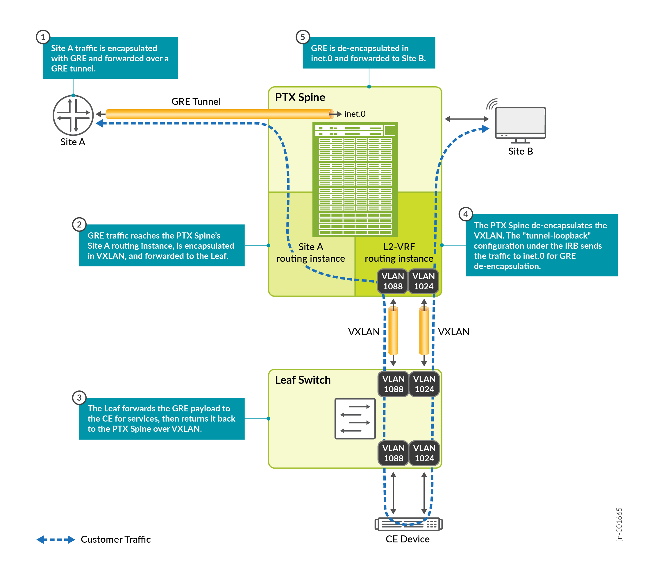
Figure 1 shows the path of the transit traffic through the VXLAN network.
In this example, the traffic at Site A is encapsulated using GRE and sent to the PTX Server.
Instead of being de-encapsulated when it reaches the PTX Spine, the GRE traffic is sent through the Site A and L2-VRF routing instances where it is further encapsulated in VXLAN then sent to the Leaf Switch.
The Leaf Switch forwards the GRE-encapsulated traffic to the CE for services. The GRE encapsulation shields the inner payload from other devices in the VXLAN network.
The CE device performs services and returns the traffic to the Leaf Switch where it is sent back to the PTX Spine using VXLAN.
The Spine receives the traffic from the Leaf Switch, de-encapsulates the VXLAN and
recognizes the GRE encapsulation. The tunnel-loopback configuration under
the IRB loops the GRE packets through inet.0 for the GRE de-encapsulation.
After the inner payload is completely de-encapsulated it is forwarded to Site B.
Example Configurations
The following examples show the relevant configurations for the devices shown in Figure 1. These configurations are focused on configuring GRE over VXLAN and do not include all the configurations necessary to implement an IP fabric underlay.
Site A
The Site A configurations include the GRE tunnel, physical interfaces, and BGP neighbors.
set chassis fpc 0 pic 0 tunnel-services bandwidth 10g
set chassis network-services enhanced-ip

set interfaces ge-0/0/0 unit 0 family inet address 10.20.0.1/24

set interfaces gr-0/0/0 unit 0 tunnel source 172.16.128.128
set interfaces gr-0/0/0 unit 0 tunnel destination 172.16.128.1
set interfaces gr-0/0/0 unit 0 family inet address 10.255.57.1/31

set interfaces ge-0/0/2 flexible-vlan-tagging
set interfaces ge-0/0/2 encapsulation flexible-ethernet-services
set interfaces ge-0/0/2 unit 100 vlan-id 100
set interfaces ge-0/0/2 unit 100 family inet address 10.100.0.2/24
set interfaces ge-0/0/2 unit 200 vlan-id 200
set interfaces ge-0/0/2 unit 200 family inet address 10.200.0.2/24

set interfaces lo0 unit 0 family inet address 172.16.128.128/32

set policy-options policy-statement bgpOut term 1 from route-filter 172.16.128.128/32 exact
set policy-options policy-statement bgpOut term 1 then accept

set policy-options policy-statement greOut term 1 from route-filter 10.20.0.0/24 exact
set policy-options policy-statement greOut term 1 then accept

set routing-instances r1 instance-type virtual-router
set routing-instances r1 routing-options static route 0.0.0.0/0 next-hop 10.200.0.1
set routing-instances r1 interface ge-0/0/2.200

set routing-options autonomous-system 65002

set protocols bgp group SiteA-PTX type external
set protocols bgp group SiteA-PTX export bgpOut
set protocols bgp group SiteA-PTX peer-as 65001
set protocols bgp group SiteA-PTX neighbor 10.100.0.1

set protocols bgp group GRE type external
set protocols bgp group GRE export greOut
set protocols bgp group GRE peer-as 65001
set protocols bgp group GRE neighbor 10.255.57.0
PTX Spine
The PTX Spine configurations include the GRE tunnel and interfaces to Site A, the Site-A and L2-VRF routing instances, the interfaces connecting to the Leaf, and the BGP groups for the various connections.
The BGP groups connect:
-
the Site-A routing instance to Site A
-
the Site-A routing instance to the local PTX Spine
-
the local PTX Spine to the Leaf
-
the local PTX Spine to the Site-A routing instance
-
the local PTX Spine to the GRE group on Site A
In addition, the tunnel-loopback configuration on IRB 1024 enables the Spine to loop
the GRE packets back for de-encapsulation after the VXLAN de-encapsulation.
set interfaces et-0/0/5 flexible-vlan-tagging
set interfaces et-0/0/5 encapsulation flexible-ethernet-services
set interfaces et-0/0/5 unit 100 vlan-id 100
set interfaces et-0/0/5 unit 100 family inet address 10.100.0.1/24
set interfaces et-0/0/5 unit 200 vlan-id 200
set interfaces et-0/0/5 unit 200 family inet address 10.200.0.1/24

set interfaces et-0/0/11 mtu 9192
set interfaces et-0/0/11 unit 0 family inet address 10.1.0.1/24

set interfaces fti0 unit 1 tunnel encapsulation gre source address 172.16.128.1
set interfaces fti0 unit 1 tunnel encapsulation gre destination address 172.16.128.128
set interfaces fti0 unit 1 tunnel encapsulation gre allow-fragmentation
set interfaces fti0 unit 1 family inet mtu 1360
set interfaces fti0 unit 1 family inet address 10.255.57.0/31

set interfaces irb mtu 9000
set interfaces irb gratuitous-arp-reply

set interfaces irb unit 1024 family inet tunnel-loopback
set interfaces irb unit 1024 family inet address 172.16.129.77/31

set interfaces irb unit 1088 family inet address 172.16.129.76/31

set interfaces lo0 unit 0 family inet address 172.16.128.1/32 primary
set interfaces lo0 unit 0 family inet6

set forwarding-options tunnel-termination

set policy-options policy-statement fti-src term 1 from protocol static
set policy-options policy-statement fti-src term 1 then next-hop self
set policy-options policy-statement fti-src term 1 then accept
set policy-options policy-statement fti-src term 2 from route-filter 172.16.128.1/32 exact
set policy-options policy-statement fti-src term 2 then next-hop self
set policy-options policy-statement fti-src term 2 then accept
set policy-options policy-statement fti-src term 3 then reject

set policy-options policy-statement gre-out term 1 from protocol direct
set policy-options policy-statement gre-out term 1 from route-filter 10.200.0.0/24 exact
set policy-options policy-statement gre-out term 1 then accept
set policy-options policy-statement gre-out term 2 then reject

set policy-options policy-statement lo0-out term 1 from route-filter 172.16.128.1/32 exact
set policy-options policy-statement lo0-out term 1 then accept
set policy-options policy-statement lo0-out term 2 from protocol bgp
set policy-options policy-statement lo0-out term 2 then accept
set policy-options policy-statement lo0-out term 3 then reject

set policy-options policy-statement nhs term 1 then next-hop self

set routing-instances Site-A instance-type virtual-router
set routing-instances Site-A routing-options autonomous-system 65001

set routing-instances Site-A protocols bgp group PTX-SiteA type external
set routing-instances Site-A protocols bgp group PTX-SiteA export lo0-out
set routing-instances Site-A protocols bgp group PTX-SiteA neighbor 10.100.0.2 peer-as 65002

set routing-instances Site-A protocols bgp group SiteA-Local type internal
set routing-instances Site-A protocols bgp group SiteA-Local local-address 172.16.129.76
set routing-instances Site-A protocols bgp group SiteA-Local export nhs
set routing-instances Site-A protocols bgp group SiteA-Local tcp-mss 1400
set routing-instances Site-A protocols bgp group SiteA-Local neighbor 172.16.129.77 family inet unicast

set routing-instances Site-A protocols ospf area 0.0.0.0 interface irb.1088
set routing-instances Site-A interface et-0/0/5.100
set routing-instances Site-A interface irb.1088

set routing-instances l2-VRF instance-type mac-vrf
set routing-instances l2-VRF protocols evpn encapsulation vxlan
set routing-instances l2-VRF protocols evpn default-gateway no-gateway-community
set routing-instances l2-VRF protocols evpn extended-vni-list all
set routing-instances l2-VRF protocols evpn remote-ip-host-routes
set routing-instances l2-VRF protocols evpn multicast-mode ingress-replication
set routing-instances l2-VRF vtep-source-interface lo0.0
set routing-instances l2-VRF service-type vlan-aware
set routing-instances l2-VRF route-distinguisher 172.16.128.1:2
set routing-instances l2-VRF vrf-target target:65001:1
set routing-instances l2-VRF vlans vlan-1024 vlan-id 1024
set routing-instances l2-VRF vlans vlan-1024 l3-interface irb.1024
set routing-instances l2-VRF vlans vlan-1024 vxlan vni 101024
set routing-instances l2-VRF vlans vlan-1088 vlan-id 1088
set routing-instances l2-VRF vlans vlan-1088 l3-interface irb.1088
set routing-instances l2-VRF vlans vlan-1088 vxlan vni 101088

set routing-options router-id 172.16.128.1
set routing-options autonomous-system 65001

set protocols bgp group spine-leaf type internal
set protocols bgp group spine-leaf local-address 172.16.128.1
set protocols bgp group spine-leaf family evpn signaling
set protocols bgp group spine-leaf neighbor 172.16.128.11

set protocols bgp group Local-SiteA type internal
set protocols bgp group Local-SiteA local-address 172.16.129.77
set protocols bgp group Local-SiteA export fti-src
set protocols bgp group Local-SiteA tcp-mss 1400
set protocols bgp group Local-SiteA neighbor 172.16.129.76 family inet unicast

set protocols bgp group GRE type external
set protocols bgp group GRE export gre-out
set protocols bgp group GRE peer-as 65002
set protocols bgp group GRE local-as 65001
set protocols bgp group GRE neighbor 10.255.57.1

set protocols ospf area 0.0.0.0 interface lo0.0 passive
set protocols ospf area 0.0.0.0 interface et-0/0/11.0 interface-type p2p
set protocols ospf area 0.0.0.0 interface irb.1024
Leaf Switch
The Leaf configurations include:
-
the interfaces to the CE device and the PTX Spine
-
the L2-VRF routing instance
-
the BGP group connecting to the PTX Spine
set interfaces et-0/0/5 unit 0 family ethernet-switching interface-mode access
set interfaces et-0/0/5 unit 0 family ethernet-switching vlan members vlan-1088

set interfaces et-0/0/7 unit 0 family ethernet-switching interface-mode access
set interfaces et-0/0/7 unit 0 family ethernet-switching vlan members vlan-1024

set interfaces et-0/0/11 mtu 9192
set interfaces et-0/0/11 unit 0 family inet address 10.1.0.2/24

set interfaces lo0 unit 0 family inet address 172.16.128.11/32
set interfaces lo0 unit 0 family inet6

set forwarding-options tunnel-termination

set routing-instances l2-VRF instance-type mac-vrf
set routing-instances l2-VRF protocols evpn encapsulation vxlan
set routing-instances l2-VRF protocols evpn default-gateway no-gateway-community
set routing-instances l2-VRF protocols evpn extended-vni-list all
set routing-instances l2-VRF protocols evpn multicast-mode ingress-replication
set routing-instances l2-VRF vtep-source-interface lo0.0
set routing-instances l2-VRF service-type vlan-aware
set routing-instances l2-VRF interface et-0/0/5.0
set routing-instances l2-VRF interface et-0/0/7.0
set routing-instances l2-VRF route-distinguisher 172.16.128.11:2
set routing-instances l2-VRF vrf-target target:65001:1
set routing-instances l2-VRF vlans vlan-1024 vlan-id 1024
set routing-instances l2-VRF vlans vlan-1024 no-arp-suppression
set routing-instances l2-VRF vlans vlan-1024 vxlan vni 101024
set routing-instances l2-VRF vlans vlan-1088 vlan-id 1088
set routing-instances l2-VRF vlans vlan-1088 no-arp-suppression
set routing-instances l2-VRF vlans vlan-1088 vxlan vni 101088

set routing-options router-id 172.16.128.11
set routing-options autonomous-system 65001

set protocols bgp group leaf-spine type internal
set protocols bgp group leaf-spine local-address 172.16.128.11
set protocols bgp group leaf-spine family evpn signaling
set protocols bgp group leaf-spine neighbor 172.16.128.1

set protocols ospf area 0.0.0.0 interface lo0.0 passive
set protocols ospf area 0.0.0.0 interface et-0/0/11.0 interface-type p2p