Fast Reroute for Egress Link Protection with EVPN-VXLAN Multihoming
You can enable the fast reroute egress link protection (ELP) feature on multihoming peer provider edge (PE) devices in an EVPN-VXLAN network. This feature improves route convergence times and avoids load-balanced traffic loss toward a multihomed customer edge (CE) device if a PE device link to the CE device fails.
Benefits
-
Avoids loss of load-balanced traffic toward a multihomed CE device when a link to the CE device fails.
-
Improves route convergence time for multihoming Ethernet segment routes in higher scaled EVPN-VXLAN fabrics.
How Fast Reroute ELP Works with Multihoming in an Ethernet Segment
In EVPN fabrics, to improve reliability and performance, customers often multihome CE devices to two or more PE devices in an Ethernet segment (ES). Multihoming helps to:
-
Safeguard against traffic loss if a PE device link to the multihomed CE device fails.
-
Enable load balancing among multiple paths to the destination.
The connections for a multihomed CE to different PE devices share an ES identifier (ESI). EVPN devices use ES routes (EVPN Type 4 routes) to advertise their local multihoming peer PE connections. The PE devices also use the ES routes to elect designated forwarders (DFs) among the peer devices to avoid sending duplicate traffic on the ESI.
With EVPN-VXLAN, a PE device connected to a multihomed CE device advertises ES tunnel routes (VXLAN tunnel routes) for each locally attached ESI. Remote PE devices receive these advertisements and create load-balancing next-hop tables for the ES. The remote PE devices use the ES next hops to load-balance traffic that is destined for a multihomed CE device among the peer PE devices associated with the ESI.
When one of the ESI links fails while a remote PE is sending traffic to the multihomed CE device:
-
The PE device with the failed link withdraws the corresponding ES route.
-
A remote PE device continues load balancing traffic toward the ESI using routes that correspond to the failed link until the device receives the route withdrawal and adjusts its load-balancing next hops.
-
The PE device with the failed link drops the excess (residual) load-balanced traffic destined for the failed link.
-
The remote PE devices receive and process the route withdrawal. The remote PE devices update their MAC address routing information and next-hop tables. At that point, the remote PE devices stop sending load-balanced traffic to the failed link.
Until the remote PE routing tables converge (which might take seconds in scaled environments), the destination CE device loses some of the traffic.
To help avoid this load-balanced traffic loss on the ESI when a member link goes down, you can enable the fast reroute ELP feature on the multihoming peer PE devices. This feature also helps improve ESI route convergence time, especially in highly-scaled networks.
- ELP with Fast Reroute in an Ethernet Segment
- ELP Tunnels with Multiple Peer PE Devices
- Fast Reroute ELP Requirements and Limitations
ELP with Fast Reroute in an Ethernet Segment
When you enable this feature on a PE device, the device creates a backup VXLAN tunnel called an ELP tunnel to each of its peer PE devices for an ES. Upon ES link failure, the PE device uses the ELP tunnel to reroute traffic to one or more of its peer PE devices.
For this feature to work, you enable it uniformly on all peer PE devices associated with an ESI. Each PE device on the ES has an ELP tunnel to all of the peer PE devices.
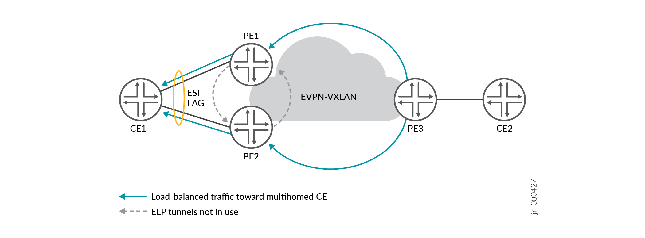
The following figures illustrate how the ELP tunnel reroute process works in a simple EVPN-VXLAN fabric where:
-
CE1 is multihomed to peer PE devices PE1 and PE2.
-
PE1 and PE2 have ELP tunnels to each other.
-
PE3 is a remote source that load-balances traffic toward CE1 using VXLAN tunnel endpoints (VTEPs) on PE1 and PE2.
In Figure 1, all the ES links toward CE1 are up, so PE1 and PE2 each forward their portions of the load-balanced traffic to CE1. PE1 and PE2 don't need to use their ELP tunnels.
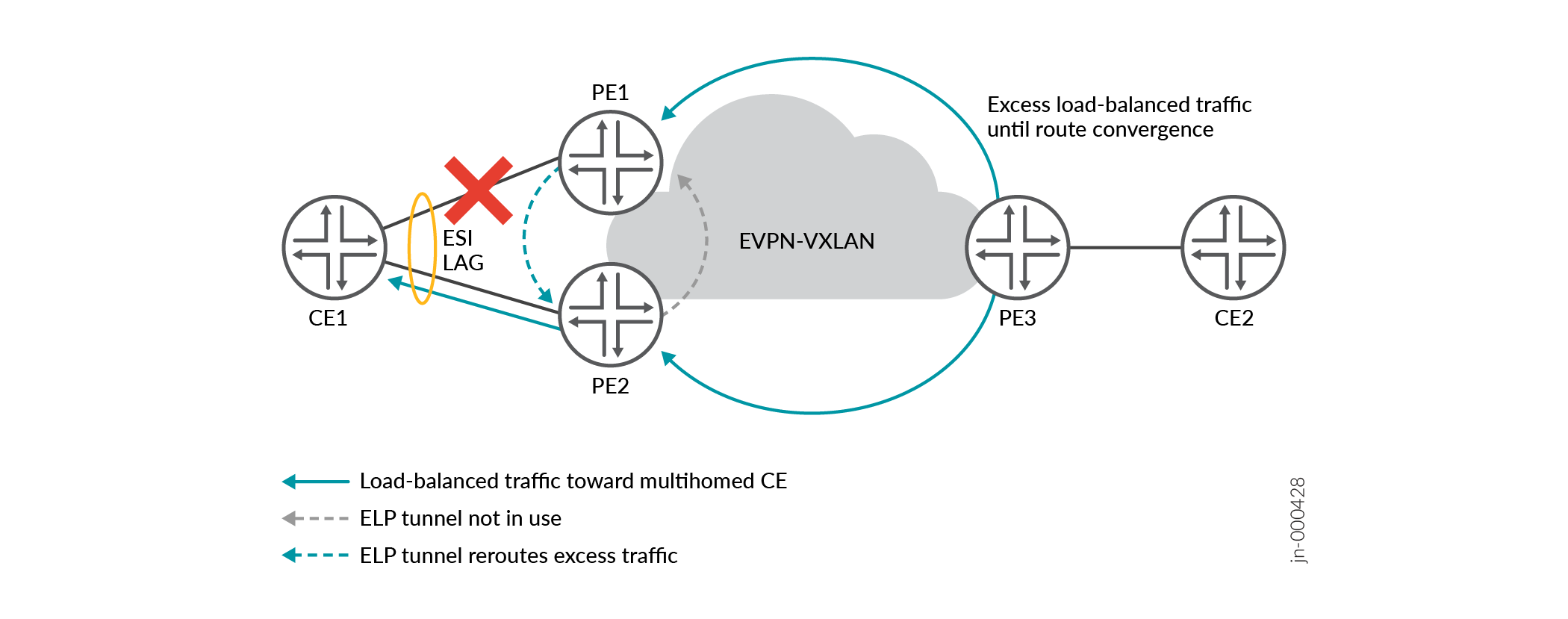
In Figure 2, the link from PE1 toward CE1 fails. PE1 withdraws the ES route for the failed link. However, until PE3 achieves route convergence, PE3 still sends some excess load-balanced traffic to PE1. Instead of dropping its portion of the load-balanced traffic, PE 1 uses its ELP tunnel to reroute that traffic to PE2. PE2 forwards both portions of the load-balanced traffic to CE1.
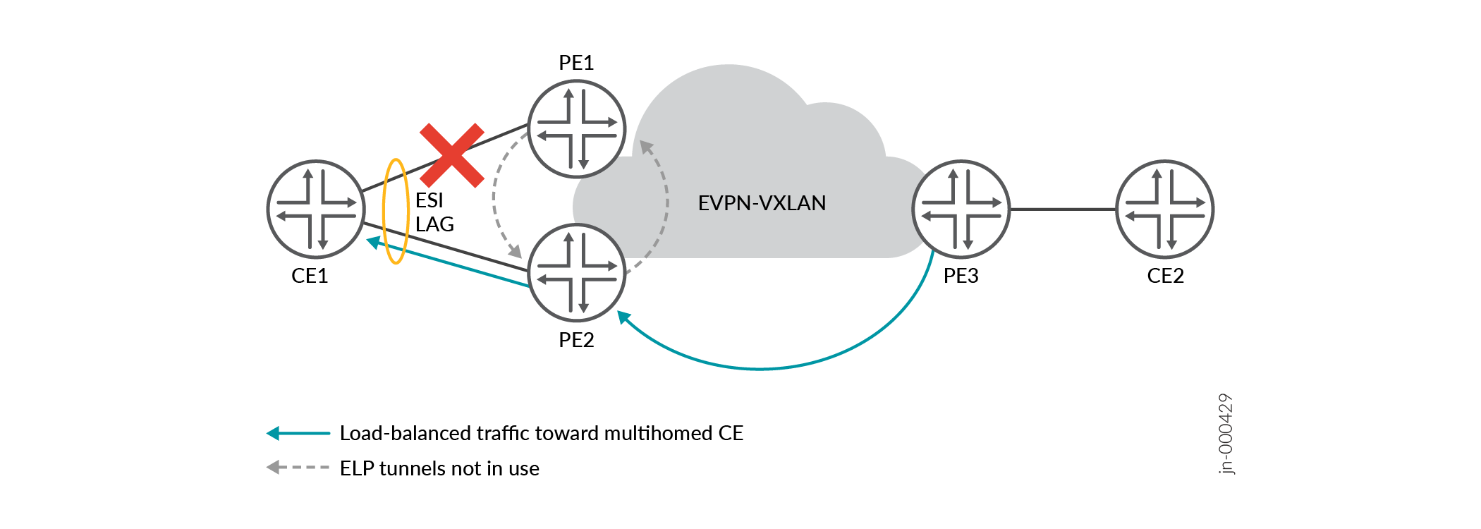
In Figure 3, PE3 achieves route convergence and stops sending any load-balanced traffic for the ES to PE1. PE3 sends all traffic for the ES only to PE2, and PE2 sends the traffic to CE1. PE1 doesn't need to use its ELP tunnel to PE2 anymore.
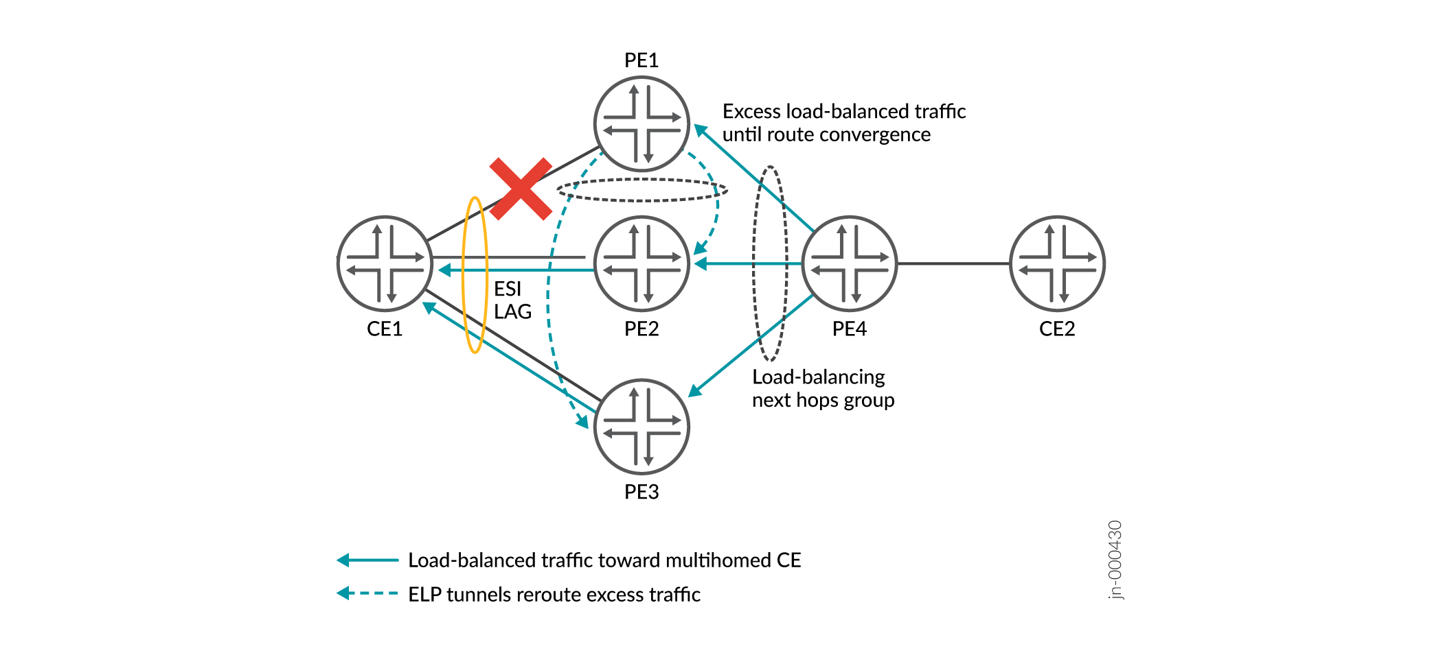
ELP Tunnels with Multiple Peer PE Devices
When you enable this feature on a PE device with two or more peer PE devices on the ES, the PE device sets up a backup VXLAN ELP tunnel to each peer PE device. See Figure 4. Each PE device maintains a next hops group for load balancing traffic destined for the ES. The remote source PE device distributes the traffic toward the ES among the next hops in the group. Each peer PE device on the ES also maintain a load-balancing next hops group with all of the ELP tunnels for the ES, so the device can also load balance rerouted traffic.
Figure 4 shows what happens if one of the links on the ES fails. In this case, the link from PE1 to CE1 fails. As a result:
-
Until PE4 achieves route convergence, PE4 still sends some excess load-balanced traffic to PE1.
-
Instead of dropping its portion of the load-balanced traffic, PE1 reroutes its excess load-balanced traffic on both of its ELP tunnels toward peer PE devices PE2 and PE3.
-
PE2 and PE3 send all of the traffic to CE1, including the load-balanced traffic they receive from PE4 and the traffic from PE1’s ELP tunnels.
-
(Not shown) PE4's routing tables converge. PE4 stops sending any traffic toward PE1 and load-balances the traffic only to PE2 and PE3.
Fast Reroute ELP Requirements and Limitations
To enable an ELP tunnel on a PE device, configure the reroute-address statement at the [edit forwarding-options evpn-vxlan]
hierarchy level. Specify the IP address the device uses for the ELP tunnel using
the inet ip-address
option to the
reroute-address statement. Configure Fast Reroute ELP on a PE Device describes more about this statement and the other steps
required to configure this feature.
With this feature:
-
You must configure this statement on all of the peer PE devices for a particular ES for the ELP tunnels on any peer PE device to work.
-
Multihoming peer PE devices do not flush MAC address table entries for aggregated Ethernet (AE) interface bundle links in active/active state when an AE ESI interface goes down. This behavior helps implement the fast reroute actions and improves route convergence times.
Fast reroute ELP has the following limitations:
-
This feature applies only with multihoming configured on AE logical interfaces.
-
We support this feature only for IPv4 client traffic.
-
This feature works for unicast traffic and VLAN flooding only, not multicast traffic.
-
We support this feature only with enterprise style interface configurations. (See Flexible Ethernet Services Encapsulation for more on this type of interface configuration.)
-
This feature handles rerouting traffic upon ES link failure on only one multihoming peer at a time that is associated with a particular ESI.
Fast reroute ELP is not supported for planned administrative link-down events
such as when you administratively disable a PE-CE interface locally on the
PE device by running the set interface
interface-name disable command. For a
planned interface-down maintenance event on the PE device, if needed, take
other administrative actions to prevent traffic loss during the maintenance.
However, if a PE-CE link goes down due to an administrative link-down
command on the CE device, the PE device detects the link failure and invokes
the fast reroute operation in that case.
Configure Fast Reroute ELP on a PE Device
You configure fast reroute ELP feature elements on supported multihoming peer PE devices for an ES. For this feature to work, you must enable it on all of the multihoming peer PE devices for the ES. You configure the steps that are listed here uniformly on each peer PE device.
You don't need to configure any corresponding elements on the multihomed CE device in the ES or on the remote source PE devices that send traffic to the ES. The CE devices and remote source PE devices can be devices that don't support this feature.
To enable the fast reroute ELP feature on a multihoming peer PE device for an ES:
Verify Fast Reroute ELP Tunnel Creation and Operation
When you enable the fast reroute ELP tunnel feature, you can use the CLI show commands in this section to see ELP tunnel IP addresses, next hop IDs, and source and remote VTEP information.
We explain some sample show command outputs here based on a topology similar to Figure 2, which we include again below for reference:
Table 1 shows the sample topology primary lo0 IP addresses for the PE devices and secondary lo0 IP addresses for their ELP tunnels:
| Device | Device IP Address | ELP Tunnel IP Address |
|---|---|---|
|
PE1 |
192.168.0.1/32 |
192.168.102.1/32 ELP tunnel from PE1 to PE2 |
|
PE2 |
192.168.0.2/32 |
192.168.201.1/32 ELP tunnel from PE2 to PE1 |
The sample topology also has these hosts (not shown) behind the CE devices in Figure 5:
| Host Description | VLAN name (VLAN ID) | MAC Address |
|---|---|---|
|
Receiver behind CE1 |
Vlan2 (VLAN ID 2) |
00:00:94:00:00:01 |
|
Remote source behind CE2 |
Vlan3 (VLAN ID 3) |
00:01:95:00:00:01 |
Finally, in this sample topology, the ESI assigned to the multihomed links from CE1 to PE1 and PE2 is 00:00:00:00:20:00:00:00:00:00.
- show ethernet-switching table
- show ethernet-switching vxlan-tunnel-end-point esi
- show ethernet-switching vxlan-tunnel-end-point remote
- show ethernet-switching vxlan-tunnel-end-point source
- show route table __default_evpn__.evpn.0 extensive
- show route table bgp.evpn.0 extensive
- show interfaces (with ELP Tunnel VTEP Interfaces)
show ethernet-switching table
Use the show ethernet-switching table mac-address
extensive command to see ELP tunnel next hops for a particular MAC
route.
For example, this output shows that PE1 will use the ELP tunnel next hop
(ELP-NH field) to send any traffic it receives to the host
behind CE1 on Vlan2 (MAC address 00:00:94:00:00:01):
user@PE1> show ethernet-switching table 00:00:94:00:00:01 extensive

MAC address: 00:00:94:00:00:01
  Routing instance: L3VRF_MVS1
  VLAN name: Vlan2, VLAN ID: 2
   Learning interface: ae0.0
   ELP-NH: 11777
   Layer 2 flags: in_hash,in_ifd,in_ifl,in_vlan,in_rtt,kernel,in_ifbd,advt_to_remote,rcvd_from_remote
   Epoch: 0                            Sequence number: 3
   Learning mask: 0x4000000000000000010000000000000000000001 BGP sequence number: 0
show ethernet-switching vxlan-tunnel-end-point esi
Use the show ethernet-switching vxlan-tunnel-end-point esi esi-identifier
esi-value
command to see the ELP tunnel VTEP
IP address, next hops and VTEP interface name.
For example, this output shows PE1 has an ELP tunnel and ELP next hop
(ELP-NH field) to remote VTEP PE2
(RVTEP-IP field) for ESI 00:00:00:00:20:00:00:00:00:00:
user@PE1> show ethernet-switching vxlan-tunnel-end-point esi esi-identifier 00:00:00:00:20:00:00:00:00:00
ESI                           RTT                      VLNBH INH     ESI-IFL   LOC-IFL   #RVTEPs
00:00:00:00:20:00:00:00:00:00 L3VRF_MVS1               28425 135034  esi.28425 ae0.0,    1      Aliasing
    LOCAL-IFL    ELP-NH    RVTEP-NH-LIST
    ae0.0          11777           11822,
    RVTEP-IP             RVTEP-IFL      VENH     MASK-ID   FLAGS        MAC-COUNT
    192.168.0.2             vtep-8.32830   11821    0         2            52
show ethernet-switching vxlan-tunnel-end-point remote
Use the show ethernet-switching vxlan-tunnel-end-point remote
command to see ELP tunnel source VTEP and remote VTEP information about a
device, including:
-
VTEP IP addresses and interface names
-
Corresponding next hop ID and ELP tunnel IP address
If the ELP-IP output field contains an IP address, that means
the remote VTEP in theRVTEP-IP column has a corresponding ELP
tunnel. Also, the ELP-IP column in the
RVTEP-IP row contains “ELP” if that
RVTEP-IP address is an ELP tunnel address.
See the sample output below and Table 3 for details on what this output means:
user@PE1> show ethernet-switching vxlan-tunnel-end-point remote
Logical System Name       Id  SVTEP-IP         IFL   L3-Idx    SVTEP-Mode    ELP-SVTEP-IP
<default>                 0   192.168.0.1      lo0.0    0                    192.168.102.1
 RVTEP-IP      IFL-Idx     Interface    NH-Id   RVTEP-Mode  ELP-IP        Flags
 192.168.0.2     2756      vtep.32830   11821   RNVE        192.168.201.1
 192.168.201.1   2757      vtep.32831   11822   RNVE        ELP
    VNID          MC-Group-IP
    530           0.0.0.0
    531           0.0.0.0
| Output Fields | Meaning |
|---|---|
|
SVTEP-IP—192.168.0.1 ELP-SVTEP-IP—192.168.102.1 |
PE1 (192.168.0.1) is the source VTEP and has an ELP tunnel with IP address 192.168.102.1 to PE2. |
|
First row under RVTEP-IP heading with: RVTEP-IP—192.168.0.2 ELP-IP—192.168.201.1 |
PE1 has PE2 (192.168.0.2) as a remote VTEP. PE2 has an ELP tunnel with IP address 192.168.201.1 to PE1. |
|
Third row under RVTEP-IP heading with: RVTEP-IP—192.168.201.1 ELP-IP—ELP |
The remote VTEP with IP address 192.168.201.1 is an ELP tunnel remote VTEP. From the other output fields in this table, we know this remote VTEP is the ELP tunnel from PE2 to PE1. |
show ethernet-switching vxlan-tunnel-end-point source
Use the show ethernet-switching vxlan-tunnel-end-point source
command to see the device ELP tunnel source VTEP IP address in the
ELP-SVTEP-IP output field.
For example, the following sample output on PE1 shows that PE1 (SVTEP
-IP 192.168.0.1) has an ELP tunnel with IP address 192.168.102.1
(ELP-SVTEP-IP) on the lo0 interface:
user@PE1> show ethernet-switching vxlan-tunnel-end-point source
Logical System Name       Id  SVTEP-IP         IFL   L3-Idx    SVTEP-Mode    ELP-SVTEP-IP
<default>                 0   192.168.0.1      lo0.0    0                    192.168.102.1
    L2-RTT                   Bridge Domain              VNID     Translation-VNID    MC-Group-IP
     L3VRF_MVS1               Vlan2+2                    2                            0.0.0.0
     L3VRF_MVS1               Vlan3+3                    3                            0.0.0.0
show route table __default_evpn__.evpn.0 extensive
The show route table __default_evpn__.evpn.0 extensive routing
table command includes the Reroute address field, which shows
the local reroute ELP tunnel address.
For example, the Reroute address field below shows that the ELP
tunnel on PE1 (192.168.0.1) has IP address 192.168.102.1:
user@PE1> show route table __default_evpn__.evpn.0 extensive

__default_evpn__.evpn.0: 2071 destinations, 2101 routes (2071 active, 0 holddown, 0 hidden)
1: 192.168.0.1:0::0::FFFF:FFFF/192 AD/ESI (1 entry, 1 announced)
        *EVPN   Preference: 170
                Next hop type: Indirect, Next hop index: 0
                Address: 0x8c06784
                Next-hop reference count: 32771, key opaque handle: 0x0, non-key opaque handle: 0x0
                Protocol next hop: 192.168.0.1

                Reroute address: 192.168.102.1
                Thread: junos-main
show route table bgp.evpn.0 extensive
The show route table bgp.evpn.0 extensive command includes the
Reroute address field showing the device ELP tunnel
address.
For example:
user@PE1> show route table bgp.evpn.0 extensive

bgp.evpn.0: 40116 destinations, 67780 routes (40116 active, 0 holddown, 0 hidden)
1: 192.168.0.1:0::0::FFFF:FFFF/192 AD/ESI (1 entry, 1 announced)
TSI:
Page 0 idx 0, (group iBGPGrp type Internal) Type 1 val 0xf820c88 (adv_entry)
   Advertised metrics:
     Flags: Nexthop Change
     Nexthop: Self
     Localpref: 100
     AS path: [55000] I

                Reroute address: 192.168.102.1
                Primary Routing Table: __default_evpn__.evpn.0
                Thread: junos-main
show interfaces (with ELP Tunnel VTEP Interfaces)
Use the show interfaces command with the ELP tunnel VTEP
interface name to see when the device reroutes traffic on the ELP tunnel.
For example, the sample command output we saw earlier in show ethernet-switching vxlan-tunnel-end-point remote shows
that the ELP tunnel VTEP interface name is vtep.32831 (the
Interface column with the remote VTEP for the tunnel to
PE2).
If you enter the show interfaces vtep.32831 command, before the
link between CE1 and PE1 fails, the Output packets field shows
that the traffic for the VTEP doesn't go over the ELP tunnel:
user@PE1> show interfaces vtep.32831
  Logical interface vtep.32831 (Index 2757) (SNMP ifIndex 2585)
    Flags: Up SNMP-Traps 0x4000 Encapsulation: ENET2
    VXLAN Endpoint Type: Shared ELP Remote, VXLAN Endpoint Address: 192.168.201.1, L3 Routing Instance: default
    Input packets : 2
    Output packets: 1
    Protocol eth-switch, MTU: Unlimited
      Flags: Trunk-Mode
After the link between CE1 and PE1 fails, the same command shows that the traffic takes the ELP tunnel path for a short time (until source routing table convergence happens):
user@PE1> show interfaces vtep.32831
  Logical interface vtep.32831 (Index 2757) (SNMP ifIndex 2585)
    Flags: Up SNMP-Traps 0x4000 Encapsulation: ENET2
    VXLAN Endpoint Type: Shared ELP Remote, VXLAN Endpoint Address: 192.168.201.1, L3 Routing Instance: default
    Input packets : 2
    Output packets: 3890
    Protocol eth-switch, MTU: Unlimited
      Flags: Trunk-Mode