Example: Configuring a QFX5110 Switch as a Layer 3 VXLAN Gateway in an EVPN-VXLAN Centrally-Routed Bridging Overlay
Ethernet VPN (EVPN) is a control plane technology that enables hosts (physical [bare-metal] servers and virtual machines [VMs]) to be placed anywhere in a network and remain connected to the same logical Layer 2 overlay network. Virtual Extensible LAN (VXLAN) is a tunneling protocol that creates the data plane for the Layer 2 overlay network.
The physical underlay network over which EVPN-VXLAN is commonly deployed is a two-layer IP fabric, which includes spine and leaf devices as shown in Figure 1. In the underlay network, the spine devices provide connectivity between the leaf devices, and the leaf devices provide connectivity to the attached physical servers and VMs on virtualized servers.
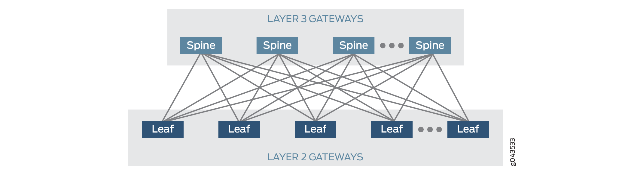
In an EVPN-VXLAN centrally-routed bridging overlay (EVPN-VXLAN topology with a two-layer IP fabric), the leaf devices function as Layer 2 VXLAN gateways that handle traffic within a VLAN, and the spine devices function as Layer 3 VXLAN gateways that handle traffic between VLANs using integrated routing and bridging (IRB) interfaces.
Prior to Junos OS Release 17.3R1, a QFX5110 switch can function only as a Layer 2 VXLAN gateway in a centrally-routed bridging overlay, all of which is deployed within a data center. Starting with Junos OS Release 17.3R1, the QFX5110 switch can also function as a Layer 3 VXLAN gateway in a centrally-routed bridging overlay.
This topic provides a sample configuration of a QFX5110 switch that functions as a spine device or Layer 3 VXLAN gateway in a centrally-routed bridging overlay. This example shows how to configure Layer 3 VXLAN gateways with IRB interfaces and default gateways.
Requirements
This example uses the following hardware and software components:
Two QFX5110 switches that function as spine devices (spine 1 and spine 2). These devices provide Layer 3 VXLAN gateway functionality.
Note:This example focuses on the configuration of the QFX5110 switch that functions as spine 1. For spine 1, a basic configuration is provided for the IP/BGP underlay network, the EVPN-VXLAN overlay network, customer-specific profiles, and route leaking. This example does not include all features that can be used in an EVPN-VXLAN network. The configuration for spine 1 essentially serves as a template for the configuration of spine 2. For the configuration of spine 2, where appropriate, you can replace spine 1-specific information with the information specific to spine 2, add additional commands, and so on.
Two QFX5200 switches that function as leaf devices (leaf 1 and leaf 2). These devices provide Layer 2 VXLAN gateway functionality.
Junos OS Release 17.3R1 or later software running on the QFX5110 and QFX5200 switches.
Physical servers in VLAN v100, and a physical server and a virtualized servers on which VMs are installed in VLAN v200.
Overview and Topology
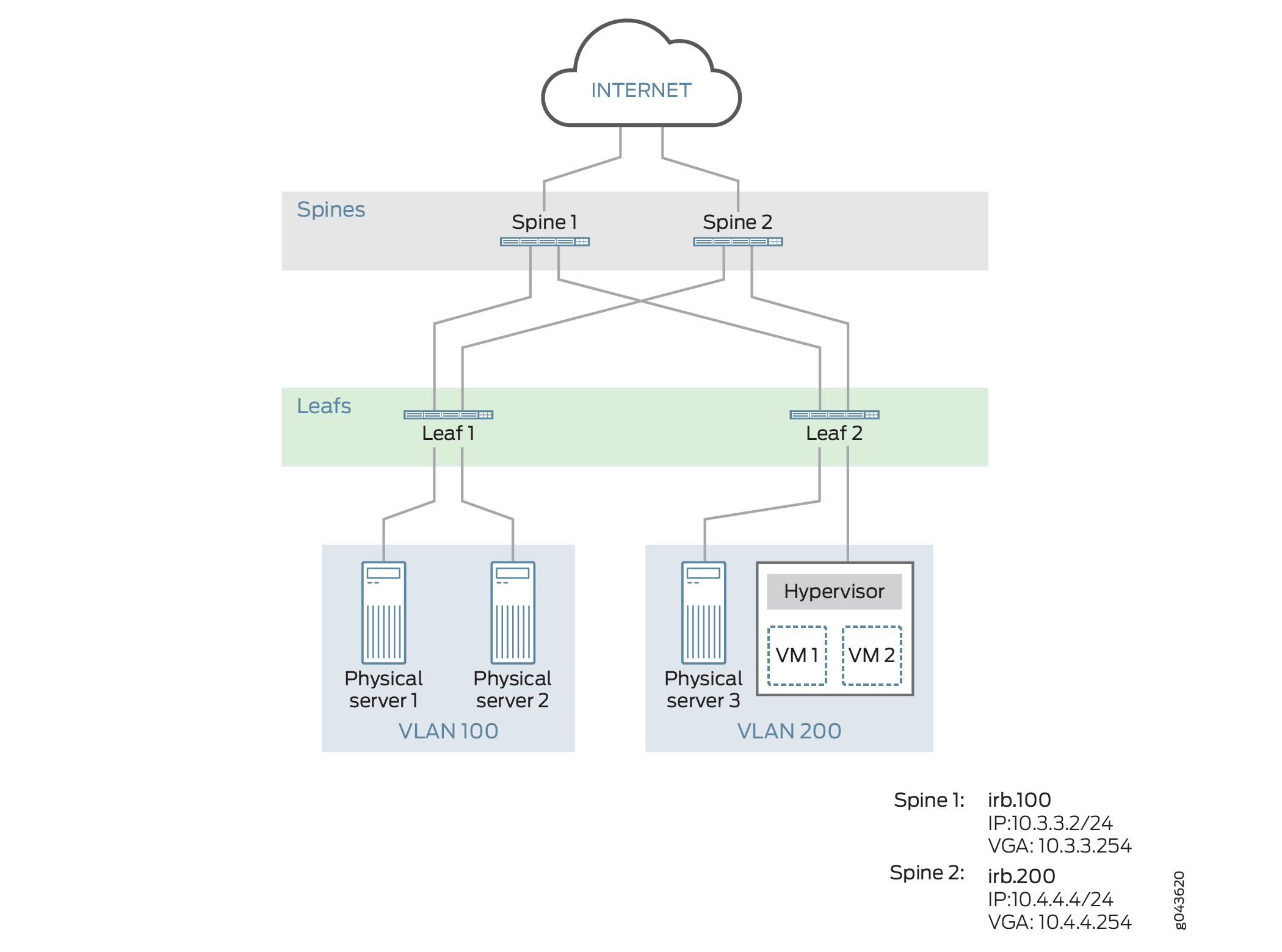
In this example, a service provider supports ABC Corporation, which has multiple sites. Physical servers in site 100 must communicate with a physical servers and VMs in site 200. To enable this communication in the centrally-routed bridging overlay shown in Figure 2, on the QFX5110 switches that function as Layer 3 VXLAN gateways, or spine devices, you configure the key software entities shown in Table 1.
Entity |
Configuration on Spine 1 and Spine 2 |
|---|---|
VLANs |
v100 v200 |
VRF instances |
vrf_vlan100 vrf_vlan200 |
IRB interfaces |
irb.100 10.3.3.2/24 (IRB IP address) 10.3.3.254 (virtual gateway address) |
irb.200 10.4.4.4/24 (IRB IP address) 10.4.4.254 (virtual gateway address) |
As outlined in Table 1, on both spine devices, you configure VLAN v100 for site 100 and VLAN v200 for site 200. To segregate the Layer 3 routes associated with VLANs v100 and v200, you create VPN routing and forwarding (VRF) instances vrf_vlan100 and vrf_vlan200 on both spine devices. To route traffic between the VLANs, you configure IRB interfaces irb.100 and irb.200 on both spine devices, and associate VRF routing instance vrf_vlan100 with IRB interface irb.100, and VRF routing instance vrf_vlan200 with IRB interface irb.200.
QFX5110 switches do not support the configuration of an IRB interface with a unique MAC address.
The physical servers in VLANs v100 and v200 are non-virtualized. As a result, we strongly recommend that you configure IRB interfaces irb.100 and irb.200 to function as default Layer 3 gateways that handle the inter-VLAN traffic of the physical servers. To that end, the configuration of each IRB interface also includes a virtual gateway address (VGA), which configures each IRB interface as a default gateway. In addition, this example assumes that each physical server is configured to use a particular default gateway. For general information about default gateways and how inter-VLAN traffic flows between a physical server to another physical server or VM in a different VLAN in a centrally-routed bridging overlay, see Using a Default Layer 3 Gateway to Route Traffic in an EVPN-VXLAN Overlay Network.
When configuring a VGA for an IRB interface, keep in mind that the IRB IP address and VGA must be different.
If a QFX5110 switch running Junos OS Release 17.3R1 or later software functions as both a Layer 3 VXLAN gateway and a Dynamic Host Configuration Protocol (DHCP) relay in an EVPN-VXLAN topology, the DHCP server response time for an IP address might take up to a few minutes. The lengthy response time might occur if a DHCP client receives and later releases an IP address on an EVPN-VXLAN IRB interface configured on the QFX5110 switch and the binding between the DHCP client and the IP address is not deleted.
As outlined in Table 1, a separate VRF routing instance is configured for each VLAN. To enable communication between the hosts in VLANs v100 and v200, this example shows how to export unicast routes from the routing table for routing instance vrf_vlan100 and import the routes into the routing table for vrf_vlan200 and vice versa. This feature is also known as route leaking.
Basic Underlay Network Configuration
CLI Quick Configuration
To quickly configure a basic underlay network,
copy the following commands, paste them into a text file, remove any
line breaks, change any details necessary to match your network configuration,
and then copy and paste the commands into the CLI at the [edit] hierarchy level.
set interfaces et-0/0/0 unit 0 family inet address 10.1.1.1/24
set interfaces et-0/0/1 unit 0 family inet address 10.2.2.1/24
set routing-options router-id 10.2.3.11
set routing-options autonomous-system 64500
set protocols bgp group pe neighbor 10.2.3.12
set protocols ospf area 0.0.0.0 interface lo0.0 passive
set protocols ospf area 0.0.0.0 interface et-0/0/0.0
set protocols ospf area 0.0.0.0 interface et-0/0/1.0
Configuring a Basic Underlay Network
Step-by-Step Procedure
To configure a basic underlay network on spine 1:
Configure the interfaces that connect to the leaf devices.
[edit interfaces]
user@switch# set et-0/0/0 unit 0 family inet address 10.1.1.1/24
user@switch# set et-0/0/1 unit 0 family inet address 10.2.2.1/24
Configure the router ID and autonomous system number for spine 1.
[edit routing-options]
user@switch# set router-id 10.2.3.11
user@switch# set autonomous-system 64500
Configure a BGP group that includes spine 2 as a peer that also handles underlay functions.
[edit protocols]
user@switch# set bgp group pe neighbor 10.2.3.12
Configure OSPF as the routing protocol for the underlay network.
[edit protocols]
user@switch# set ospf area 0.0.0.0 interface lo0.0 passive
user@switch# set ospf area 0.0.0.0 interface et-0/0/0.0
user@switch# set ospf area 0.0.0.0 interface et-0/0/1.0
Basic EVPN-VXLAN Overlay Network Configuration
CLI Quick Configuration
To quickly configure a basic overlay network,
copy the following commands, paste them into a text file, remove any
line breaks, change any details necessary to match your network configuration,
and then copy and paste the commands into the CLI at the [edit] hierarchy level.
set forwarding-options vxlan-routing  interface-num 8192
set forwarding-options vxlan-routing next-hop 16384
set protocols bgp group pe type internal
set protocols bgp group pe local-address 10.2.3.11
set protocols bgp group pe family evpn signaling
set protocols evpn encapsulation vxlan
set protocols evpn extended-vni-list all
set protocols evpn default-gateway no-gateway-community
set  switch-options route-distinguisher 10.2.3.11:1
set  switch-options vrf-target target:1111:11
set  switch-options vtep-source-interface lo0.0
Configuring a Basic EVPN-VXLAN Overlay Network
Step-by-Step Procedure
To configure a basic EVPN-VXLAN overlay network on spine 1:
Increase the number of physical interfaces and next hops that the QFX5110 switch allocates for use in an EVPN-VXLAN overlay network.
[edit forwarding-options]
set vxlan-routing  interface-num 8192
set vxlan-routing  next-hop 16384
Configure an IBGP overlay between spine 1 and the connected leaf devices, specify a local IP address for spine 1, and include the EVPN signaling Network Layer Reachability Information (NLRI) to the pe BGP group.
[edit protocols]
user@switch# set bgp group pe type internal
user@switch# set bgp group pe local-address 10.2.3.11
user@switch# set bgp group pe family evpn signaling
Configure VXLAN encapsulation for the data packets exchanged between the EVPN neighbors, and specify that all VXLAN network identifiers (VNIs) are part of the virtual routing and forwarding (VRF) instance. Also, specify that the MAC address of the IRB interface and the MAC address of the corresponding default gateway are advertised to the Layer 2 VXLAN gateways without the extended community option of default -gateway.
[edit protocols]
user@switch# set evpn encapsulation vxlan
user@switch# set evpn extended-vni-list all
user@switch# set evpn default-gateway no-gateway-community
Configure switch options to set a route distinguisher and VRF target for the VRF routing instance, and associate interface lo0 with the virtual tunnel endpoint (VTEP).
[edit switch-options]
user@switch# set  route-distinguisher 10.2.3.11:1
user@switch# set  vrf-target target:1111:11
user@switch# set  vtep-source-interface lo0.0
Basic Customer Profile Configuration
CLI Quick Configuration
To quickly configure a basic customer profile
for ABC Corporation sites 100 and 200, copy the following commands,
paste them into a text file, remove any line breaks, change any details
necessary to match your network configuration, and then copy and paste
the commands into the CLI at the [edit] hierarchy level.
set interfaces xe-0/0/32:1 unit 0 family ethernet-switching interface-mode trunk
set interfaces xe-0/0/32:1 unit 0 family ethernet-switching vlan members v100
set interfaces xe-0/0/32:1 unit 0 family ethernet-switching vlan members v200
set interfaces irb unit 100 family inet address 10.3.3.2/24 virtual-gateway-address 10.3.3.254
set interfaces irb unit 100 proxy-macip-advertisement
set interfaces irb unit 200 family inet address 10.4.4.4/24 virtual-gateway-address 10.4.4.254
set interfaces irb unit 200 proxy-macip-advertisement
set interfaces lo0 unit 0 family inet address 10.2.3.11/32 primary
set interfaces lo0 unit 1 family inet address 10.2.3.24/32 primary
set interfaces lo0 unit 2 family inet address 10.2.3.25/32 primary
set routing-instances vrf_vlan100 instance-type vrf
set routing-instances vrf_vlan100 interface irb.100
set routing-instances vrf_vlan100 interface lo0.1
set routing-instances vrf_vlan100 route-distinguisher 10.2.3.11:2
set routing-instances vrf_vlan100 vrf-import import-inet
set routing-instances vrf_vlan100 vrf-export export-inet1
set routing-instances vrf_vlan200 instance-type vrf
set routing-instances vrf_vlan200 interface irb.200
set routing-instances vrf_vlan200 interface lo0.2
set routing-instances vrf_vlan200 route-distinguisher 10.2.3.11:3
set routing-instances vrf_vlan200 vrf-import import-inet
set routing-instances vrf_vlan200 vrf-export export-inet2
set vlans v100 vlan-id 100
set vlans v100 l3-interface irb.100
set vlans v100 vxlan vni 100
set vlans v200 vlan-id 200
set vlans v200 l3-interface irb.200
set vlans v200 vxlan vni 200
Configuring a Basic Customer Profile
Step-by-Step Procedure
To configure a basic customer profile for ABC Corporation sites 100 and 200 on spine 1:
Configure a Layer 2 interface, and specify the interface as a member of VLANs v100 and v200.
[edit interfaces]
user@switch# set xe-0/0/32:1 unit 0 family ethernet-switching interface-mode trunk
user@switch# set xe-0/0/32:1 unit 0 family ethernet-switching vlan members v100
user@switch# set xe-0/0/32:1 unit 0 family ethernet-switching vlan members v200
Create IRB interfaces, and configure the interfaces to act as default Layer 3 virtual gateways, which route traffic from physical servers in VLAN v100 to physical servers and VMs in VLAN v200 and vice versa. Also, on the IRB interfaces, enable the Layer 3 VXLAN gateway to advertise MAC+IP type 2 routes on behalf of the Layer 2 VXLAN gateways.
[edit interfaces]
user@switch# set irb unit 100 family inet address 10.3.3.2/24 virtual-gateway-address 10.3.3.254
user@switch# set irb unit 100 proxy-macip-advertisement
user@switch# set irb unit 200 family inet address 10.4.4.4/24 virtual-gateway-address 10.4.4.254
user@switch# set irb unit 200 proxy-macip-advertisement
Note:QFX5110 switches do not support the configuration of an IRB interface with a unique MAC address.
Note:When configuring a VGA for an IRB interface, keep in mind that the VGA and IRB IP address must be different.
Configure a loopback interface (lo0) for spine 1 and a logical loopback address (lo0.x) for each VRF routing instance.
[edit interfaces]
user@switch# set lo0 unit 0 family inet address 10.2.3.11/32 primary
user@switch# set lo0 unit 1 family inet address 10.2.3.24/32 primary
user@switch# set lo0 unit 2 family inet address 10.2.3.25/32 primary
Configure VRF routing instances for VLANs v100 and v200. In each routing instance, associate an IRB interface, a loopback interface, and an identifier attached to the route. Also specify that each routing instance exports its overlay routes to the VRF table for the other routing instance and imports overlay routes from the VRF table for the other routing instance into its VRF table.
[edit routing-instances]
user@switch# set vrf_vlan100 instance-type vrf
user@switch# set vrf_vlan100 interface irb.100
user@switch# set vrf_vlan100 interface lo0.1
user@switch# set vrf_vlan100 route-distinguisher 10.2.3.11:2
user@switch# set vrf_vlan100 vrf-import import-inet
user@switch# set vrf_vlan100 vrf-export export-inet1
user@switch# set vrf_vlan200 instance-type vrf
user@switch# set vrf_vlan200 interface irb.200
user@switch# set vrf_vlan200 interface lo0.2
user@switch# set vrf_vlan200 route-distinguisher 10.2.3.11:3
user@switch# set vrf_vlan200 vrf-import import-inet
user@switch# set vrf_vlan200 vrf-export export-inet2
Configure VLANs v100 and v200, and associate an IRB interface and VNI with each VLAN.
[edit vlans]
user@switch# set v100 vlan-id 100
user@switch# set v100 l3-interface irb.100
user@switch# set v100 vxlan vni 100
user@switch# set v200 vlan-id 200
user@switch# set v200 l3-interface irb.200
user@switch# set v200 vxlan vni 200
Route Leaking Configuration
Procedure
CLI Quick Configuration
To quickly configure route leaking, copy the
following commands, paste them into a text file, remove any line breaks,
change any details necessary to match your network configuration,
and then copy and paste the commands into the CLI at the [edit] hierarchy level.
set policy-options policy-statement export-inet1 term 1 from interface irb.100
set policy-options policy-statement export-inet1 term 1 then community add com200
set policy-options policy-statement export-inet1 term 1 then accept
set policy-options policy-statement export-inet2 term 1 from interface irb.200
set policy-options policy-statement export-inet2 term 1 then community add com100
set policy-options policy-statement export-inet2 term 1 then accept
set policy-options policy-statement import-inet term 1 from community com100
set policy-options policy-statement import-inet term 1 from community com200
set policy-options policy-statement import-inet term 1 then accept
set policy-options community com100 members target:1:100
set policy-options community com200 members target:1:200
set routing-instances vrf_vlan100 vrf-import import-inet
set routing-instances vrf_vlan100 vrf-export export-inet1
set routing-instances vrf_vlan100 routing-options auto-export family inet unicast
set routing-instances vrf_vlan200 vrf-import import-inet
set routing-instances vrf_vlan200 vrf-export export-inet2
set routing-instances vrf_vlan200 routing-options auto-export family inet unicast
Step-by-Step Procedure
To configure route leaking on spine 1:
Configure a routing policy that specifies that routes learned through IRB interface irb.100 are exported and then imported into the routing table for vrf_vlan200. Configure another routing policy that specifies that routes learned through IRB interface irb.200 are exported and then imported into the routing table for vrf_vlan100.
[edit policy-options]
user@switch# set policy-statement export-inet1 term 1 from interface irb.100
user@switch# set policy-statement export-inet1 term 1 then community add com200
user@switch# set policy-statement export-inet1 term 1 then accept
user@switch# set policy-statement export-inet2 term 1 from interface irb.200
user@switch# set policy-statement export-inet2 term 1 then community add com100
user@switch# set policy-statement export-inet2 term 1 then accept
user@switch# set policy-statement import-inet term 1 from community com100
user@switch# set policy-statement import-inet term 1 from community com200
user@switch# set policy-statement import-inet term 1 then accept
user@switch# set community com100 members target:1:100
user@switch# set community com200 members target:1:200
In the VRF routing instances for VLANs v100 and v200. apply the routing policies configured in step 1.
[edit routing-instances]
user@switch# set vrf_vlan100 vrf-import import-inet
user@switch# set vrf_vlan100 vrf-export export-inet1
user@switch# set vrf_vlan200 vrf-import import-inet
user@switch# set vrf_vlan200 vrf-export export-inet2
Specify that unicast routes are to be exported from the vrf_vlan100 routing table into the vrf_vlan200 routing table and vice versa.
[edit routing-instances]
user@switch# set vrf_vlan100 routing-options auto-export family inet unicast
user@switch# set vrf_vlan200 routing-options auto-export family inet unicast