Overview of Headend Termination for EVPN VPWS for Business Services
Currently, Junos OS only supports pseudowire subscriber logical interface to be used with Layer 2 circuit or Layer 2 VPN for pseudowire headend termination. An Ethernet VPN (EVPN) enables you to connect dispersed customer sites using a Layer 2 virtual bridge. Virtual private wire service (VPWS) Layer 2 VPNs employ Layer 2 services over MPLS to build a topology of point-to-point connections that connect end customer sites in a VPN. EVPN-VPWS as a next generation of pseudowire technology brings the benefit of EVPN to point-to-point service by providing fast convergence upon node failure and link failure through its multi-homing feature. As a result, you can use EVPN-VPWS and pseudowire subscriber interface for headend termination into different services.
The pseudowire headend termination support with pseudowire subscriber interface works with EVPN-VPWS Flexible Cross Connect (FXC) in the vMX (Virtual MX) scale out solution. The vMX scale out support with EVPN-VPWS FXC is terminated into Layer 3 VRF or BGP-VPLS through pseudowire subscriber interface on vMX
The multi-home scenario includes support for either two or more than two PEs.
Benefits of Pseudowire Headend Termination (PWHT) with EVPN-VPWS Pseudowires:
-
PWHT framework can be used to attach remote CEs (reachable via metro aggregation network) to the services (for example Layer 3 VPN) available on service PE in a similar way to CEs which are directly attached to service PEs.
-
Multiple VLANs can be transported inside pseudowire and demultiplexed to different services on service PE using pseudowire subscriber logical interfaces just like VLANs on regular physical interfaces.
-
PWHT with EVPN-VPWS as transport pseudowire brings further numerous benefits; for example unified BGP based control plane for all services in metro aggregation and core network, or redundant active-standby transport connectivity between multiple service PEs and multiple aggregation nodes.
Pseudowire Subscriber Logical Interface Support for EVPN-VPWS
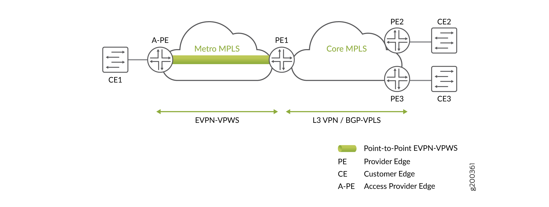
Figure 1 illustrates an EVPN-VPWS network with pseudowire service. A-PE (Access Provider Edge) is the access router and PE1 is the service edge router. A pseudowire subscriber logical interface is used on PE1 to terminate the pseudowire established by EVPN-VPWS into either Layer 3 VPN or Layer 2 BGP-VPLS service. There is only one single service edge router to terminate the pseudowire, in this scenario.
For a given pseudowire subscriber logical interface, for example ps0, only the transport interface of the pseudowire subscriber logical interface, that is ps0.0, is used as an access interface for the EVPN-VPWS on PE1. The service interfaces of ps0, that is ps0.1 to ps0.n, are used at the service side (either under Layer 3 VRF or BGP-VPLS instance).
Prior to Junos OS 18.2 Release, the only encapsulation type that pseudowire
subscriber transport logical interface (as an access interface for the
pseudowire) supports for Layer 2 circuit and Layer 2 VPN is
ethernet-ccc. This encapsulation type will remain the same
for EVPN-VPWS with pseudowire subscriber logical interface support as well.
- Single Pseudowire Headend Termination
- Active-Standby Pseudowire Headend Termination
- Active-Active Pseudowire Headend Termination
Single Pseudowire Headend Termination
The pseudowire subscriber transport logical interface is used as the access interface for EVPN-VPWS instance. EVPN establishes a point-to-point Ethernet service with pseudowire subscriber transport logical interface as an access interface in the control plane.
Active-Standby Pseudowire Headend Termination
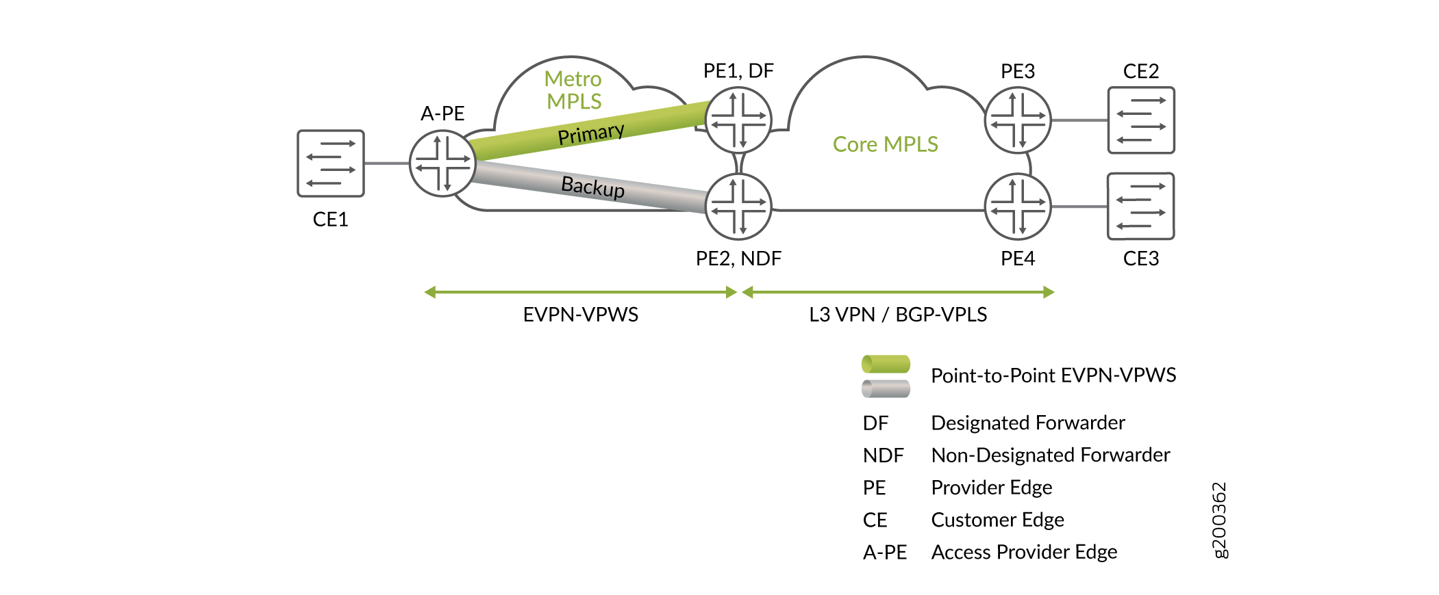
As shown in Figure 2, to achieve resilience for pseudowire headend termination into Layer 3 VPN or BGP-VPLS, you can use a pair of redundant pseudowires on the EVPN-VPWS side. Also, in Figure 2, Layer 3 VPN or BGP-VPLS is treated as if it is multi-homed to the set of redundant service edge routers, PE1 and PE2. PE1 and PE2 work in active-standby mode for EVPN-VPWS. One of them is elected as the primary PE per EVPN normal designated forwarder (DF) election procedure. Only the primary PE is used to forward Layer 2 traffic.
Following are the reasons for the pseudowire failure, when redundancy is provided by the EVPN-VPWS active-standby interface:
-
Service edge router node failure.
-
Pseudowire subscriber transport logical interface failure on the primary PE.
-
Failure on the path towards the primary PE.
If any of the above failure cases are detected, the backup PE takes over to become the primary PE. As a result, the customer traffic from the access router, A-PE, is switched to the new primary PE.
The EVPN-VPWS also supports the service side of the network multi-homing to EVPN-VPWS through the pseudowire subscriber logical interface in an active-standby mode.
To achieve active-standby pseudowire headend termination, the following is required:
-
Ethernet segment identifier (ESI) support on the pseudowire subscriber transport logical interface.
-
Synchronizing data path between active pseudowire and Layer 3 VPN.
-
MAC flush in the BGP-VPLS when the active-standby pseudowires switch. MAC flush is triggered when the active service edge node suffers a node failure.
ES Support on Pseudowire Subscriber Transport Logical Interface
An Ethernet segment must have a unique nonzero identifier, called the Ethernet segment identifier (ESI). The ESI is encoded as a 10-octet integer. When manually configuring an ESI value, the most significant octet, known as the type byte, must be 00. ESI is assigned to pseudowire subscriber transport logical interfaces associated with the PE1 and PE2 the same way as in EVPN multi-homing.
To configure the active-standby mode for the pseudowire subscriber
transport logical interface, include the ESI value and the
single-active statement under the [edit
interfaces] hierarchy level.
DF Election and Pseudowire Subscriber Transport Logical Interface
Designated forwarder(DF)—This is the designated forwarder for forwarding the current traffic. The DF election procedure ensures each VLAN is associated with single PE acting in DF role.
Synchronizing Data Path between EVPN-VPWS and Layer 3 VPN or BGP-VPLS
There is a need for the data path coordination between the point-to-point pseudowire and the services side of the network (Layer 3 VPN or BGP-VPLS), with active-standby pseudowire headend termination. This is to select the same service edge router for passing the current traffic between the point-to-point pseudowire and Layer 3 VPN or BGP-VPLS domain.
EVPN-VPWS determines the primary path, for both Layer 3 VPN and BGP-VPLS, based on its DF election result. Both the primary and backup PEs for EVPN-VPWS then influence the services side of network to use the primary PE for data traffic.
Layer 3 VPN
When pseudowires are headend terminated into the Layer 3 VPN in an active-standby mode, the primary and the backup PEs use routing-policy and policy-condition to increase or decrease the Local Preference (LP). As a result, the BGP path selection algorithm is carried out on the Layer 3 side and picks up the primary PE.
BGP-VPLS
EVPN-VPWS establishes active-standby pseudowires based on its DF election. The active-standby pseudowires are essentially the two redundant spoke pseudowires attached to BGP-VPLS instance. The BGP-VPLS PEs remain single homed PEs and data plane learning happens through the active pseudowire in the EVPN-VPWS primary path.
-
If the pseudowire subscriber service logical interface that belongs to a BGP-VPLS instance is in down state, this does not trigger the active and standby pseudowire switch on the EVPN-VPWS side. This is because the 1 to many relationships between the point-to-point pseudowire and the BGP-VPLS. This may cause traffic loss for traffic coming from the VPLS to the point-to-point pseudowire direction.
-
BGP-VPLS does not trigger MAC flush when its access link to the CE device goes up or down. Further, since multi-homed EVPN-VPWS pseudowire headend termination into BGP-VPLS is based on single-homed mode on BGP-VPLS side, MAC flush (achieved via manipulation of F-bit in BGP-VPLS messages) associated with multi-homed BGP-VPLS mode does not apply here, neither. Therefore, when there is DF or NDF state change on EVPN-VPWS side, or if the pseudowire subscriber service logical interface that belongs to a BGP-VPLS instance goes up or down, MAC flush is not triggered. Null-route filtering might occur until expiration of MAC aging timer, unless there is constant traffic from the CE behind the EVPN-VPWS to BGP-VPLS. MAC flush is triggered only during PE node failures.
The following configuration example shows how condition manager is used for Layer 3 VPN routing instance through vrf-export when active-standby EVPN-VPWS terminates into Layer 3 VPN service.
[edit]
routing-instances {
    l3vpn_1 {
        instance-type vrf;
        interface ps0.1;
        interface lo0.1;
        route-distinguisher 2.2.2.3:6500;
        vrf-import l3vpn_1_import;
        vrf-export l3vpn_1_export;
        vrf-table-label;
        protocols {
             bgp {
                group toPW-CE1 {
                    type external;
                    export send-direct;
                    peer-as 1;
                    neighbor 10.1.1.1;
                }
            }
        }
    }
}
policy-options {
    policy-statement l3vpn_1_export {
        term 1 {
            from condition primary;
            then {
                local-preference add 300;
                community set l3vpn_1;
                accept;
            }
        }
        term 2 {
            from condition standby;
            then {
                community set l3vpn_1;
                accept;
            }
        }
    }
    policy-statement l3vpn_1_import {
        term 1 {
            from community l3vpn_1;
            then accept;
        }
        term default {
            then reject;
        }
    }
    community l3vpn_1 members target:65056:100;
    condition primary {
        if-route-exists {
            address-family {
                ccc {
                    ps0.0;
                    table mpls.0;
                }
            }
        }
    }
    condition standby {
        if-route-exists {
            address-family {
                ccc {
                    ps0.0;
                    table mpls.0;
                    standby;
                }
            }
        }
    }
}
Following is the BGP-VPLS instance configuration when EVPN-VPWS terminates into the BGP-VPLS:
[edit]
routing-instances {
    vpls-1 {
        instance-type vpls;
        interface ps0.1;
        route-distinguisher 100:2;
        vrf-target target:100:100;
        protocols {
            vpls {
                site ce3 {
                    site-identifier 3;
                }
            }
        }
    }
}
Active-Active Pseudowire Headend Termination
Active-active pseudowire headend termination is not supported both in Layer 3 VPN and in BGP-VPLS.
vMX Scale Out
The vMX router is a virtual version of the MX Series 5G Universal Routing Platform. Like the MX Series router, the vMX router runs the Junos operating system (Junos OS) and supports Junos OS packet handling and forwarding modeled after the Trio chipset. The vMX instance contains two separate virtual machines (VMs), one for the virtual forwarding plane (VFP) and one for the virtual control plane (VCP). The VFP VM runs the virtual Trio forwarding plane software and the VCP VM runs Junos OS.
The vMX can now be used to scale out the bandwidth, achieve service isolation, and resilience. As the service edge router, vMX supports pseudowire headend termination with active and standby mode.
vMX
A vMX can have active and backup VCP with one or more VFPs. The VCP is the RE and the VFP is the line-card. The communication between VCP and VFP is facilitated through vRouter, if the VCP and VFP reside on the same server. Else, it is through the external network to which the servers are connected. There is no direction communication between VFPs.
Service Isolation
For a given point-to-point pseudowire with only one VFP per vMX, the data traffic is handled by one VFP for both ingress and egress traffic.
Active-Standby Pseudowire Headend Termination into VMX
The vMX acts as a regular MX for the overlay point-to-point Ethernet service. Similar to physical MX router, redundancy is achieved by using multiple vMXs, and only active-standby pseudowire headend termination is supported. The pseudowire is terminated at the loopback IP address that is used as the protocol nexthop address for the pseudowire.