PFC Functionality Across L3 Interfaces
Priority-based flow control (PFC) allows you to select traffic flows within a link and pause these flows, so that the output queues associated with the flows do not overflow and drop packets. PFC is more granular than Ethernet PAUSE, which pauses all traffic on a physical link. PFC helps you configure lossless transport for traffic flows across a data center bridging (DCB) network.
However, you might want to create a traffic flow that losslessly traverses the L2 DCB network and also losslessly traverses an L3 network that connects Ethernet hosts in different L2 networks. In addition to configuring PFC on L2 (bridging) interfaces, you can configure PFC on VLAN-tagged traffic that traverses L3 interfaces. This enables you to preserve the lossless characteristics that PFC provides on VLAN-tagged traffic, even when the traffic crosses L3 interfaces that connect two L2 networks.
This topic is applicable for VLAN-tagged traffic only. On supported platforms, you can configure DSCP-based PFC for untagged traffic on L3 interfaces and L2 access interfaces. DSCP-based PFC uses a DSCP classifier to classify the traffic based on a 6-bit DSCP value that is mapped to a 3-bit PFC priority value. For details on using DSCP-based PFC on supporting switches, see Understanding PFC Using DSCP at Layer 3 for Untagged Traffic.
PFC works the same way across L3 interfaces as it works across L2 interfaces. When an output queue buffer reaches a certain fill level threshold, the switch sends a PFC pause message to the connected peer to pause transmission of the traffic on which PFC is enabled. Pausing the incoming traffic prevents the queue buffer from overflowing and dropping packets, just as on L2 interfaces. When the queue buffer fill level decreases below a certain threshold, the interface sends a message to the connected peer to restart traffic transmission.
Although PFC is a DCB technology, PFC also works on L3 interfaces because PFC operates at the queue level. When you use an IEEE 802.1p code point to classify incoming traffic and you enable PFC on the appropriate priority (IEEE 802.1p code point), PFC works on L2 and L3 interfaces.
Lossless VLAN-tagged traffic on L3 interfaces must use an IEEE 802.1p classifier to classify incoming traffic. PFC does not use DSCP or DSCP IPv6 code points to identify VLAN-tagged traffic for flow control. PFC cannot pause traffic flows unless the incoming traffic is classified by an IEEE 802.1p classifier. Do not apply a DSCP (or a DSCP IPv6) classifier to L3 VLAN-tagged traffic on which you want to enable PFC.
Because PFC functionality relies on the mapping (classifying) of incoming traffic to IEEE 802.1p code points and on enabling PFC on the correct code point(s) at each interface, you must ensure that incoming traffic has the correct 3-bit IEEE 802.1p code point (priority) in the priority code point (PCP) field of the Ethernet frame header.
L3 interfaces do not support FCoE traffic. FCoE traffic must use L2 interfaces and cannot use L3 interfaces. Therefore, you cannot enable PFC on FCoE traffic across L3 interfaces.
Figure 1 shows a topology in which two Ethernet hosts in Layer 2 networks communicate across a Layer 3 network, with PFC enabled on all of the Layer 2 and Layer 3 switch interfaces.
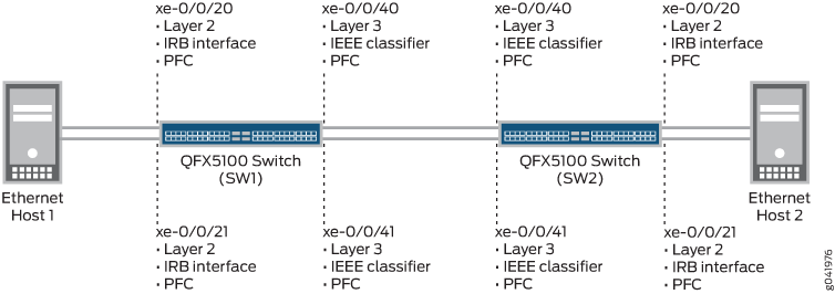
The Ethernet host-facing interfaces (xe-0/0/20 and xe-0/0/21 on both switches) and the L3 network-facing interfaces (interfaces xe-0/0/40 and xe-0/0/41 on both switches) require different interface configurations to enable PFC on the L3 interfaces. In addition, you must configure CoS for each interface correctly, including enabling PFC on the traffic that you want to treat as lossless traffic:
Ethernet-host facing interfaces (xe-0/0/20 and xe-0/0/21) require the following configuration:
-
Set interfaces as family ethernet-switching
-
Set the interface mode as trunk mode
-
Create VLANs to carry the traffic
-
Create IRB interfaces to place the L2 VLAN traffic on L3 for transport between IP networks
-
Create an IEEE 802.1p classifier to classify incoming traffic into the correct forwarding class, based on the IEEE 802.1p code point
-
Create a CNP to configure PFC on the IEEE 802.1p code point of the traffic that you want treat as lossless traffic
-
Apply the classifier and the CNP to the L2 interfaces
-
Configure CoS: lossless forwarding classes, hierarchical port scheduling (also known as enhanced transmission selection), or direct port scheduling, depending on your switch, and apply it to the L2 interfaces
L3 IP network-facing interfaces (xe-0/0/40 and xe-0/0/41) require the following configuration:
-
Set interfaces as family inet
-
Set VLAN tagging on the interfaces
-
Create VLANs to carry the traffic
-
Create an IEEE 802.1p classifier to classify incoming traffic into the correct forwarding class, based on the IEEE 802.1p code point (do not use a DSCP or DSCP IPv6 classifier)
-
Create a CNP to configure PFC on the IEEE 802.1p code point of the traffic that you want to treat as lossless traffic on the L3 interfaces
-
Apply the IEEE 802.1p classifier and the CNP to the L3 interfaces
-
Configure CoS: lossless forwarding classes, hierarchical port scheduling (enhanced transmission selection), or direct port scheduling, depending on your switch, and apply it to the L3 interfaces
Configuring or changing PFC on an interface blocks the entire port until the PFC change is completed. After a PFC change is complete, the port is unblocked and traffic resumes. Blocking the port stops ingress and egress traffic and causes packet loss on all queues on the port until the port is unblocked.
When you configure the Layer 2 and Layer 3 interfaces correctly, the switch enables PFC on the traffic between Ethernet Host 1 and Ethernet Host 2 across the entire path between the two hosts. If any output queue in the path on which PFC is enabled experiences congestion, PFC pauses the traffic and prevents packet loss for the flow.