ON THIS PAGE
Example: Rewriting CoS Information at the Network Border to Enforce CoS Strategies
This example shows how to rewrite (remark) class-of-service (CoS) values at the network border to enforce your internal CoS strategies. This is typically done when the CoS values of the inbound traffic at the network border cannot be trusted, or the values do not match your internal network’s CoS strategy.
A thorough explanation of the CoS rewriting and its underlying algorithms is beyond the scope of this document. For more information about traffic policing, and CoS in general, refer to QOS-Enabled Networks—Tools and Foundations by Miguel Barreiros and Peter Lundqvist. This book is available at many online booksellers and at www.juniper.net/books .
Requirements
To verify this procedure, this example uses a traffic generator. The traffic generator can be hardware-based or it can be software running on a server or host machine.
The functionality in this procedure is widely supported on devices that run Junos OS. The example shown here was tested and verified on MX Series routers running a supported Junos OS release.
Overview
The purpose of this example is to demonstrate CoS rewriting at a network border to convey the traffics’s CoS profile to the next-hop router, based on the forwarding class and packet loss priority (PLP) assigned to the traffic. CoS information rewriting is performed as the last step before a packet is transmitted onto the egress network.
In this example the rewriting is done when sending traffic from the host connected to Device R1 to the host connected to Device R2. The information required for rewriting the CoS parameters in the other direction is not included in this example. However, you can use the rewriting information in Device R1 (making changes for the interfaces used) and apply it to Device R2 to achieve bidirectional CoS rewriting.
Junos OS contains several default rewrite rules that might meet your requirements. You display
them with the show class-of-service rewrite-rule command. Table 1 shows a partial list of
the default rewrite rule mapping.
|
Map from Forwarding Class |
PLP Value |
MAP to DSCP/DSCP IPv6/EXP/IP Code Point Aliases |
|---|---|---|
|
expedited-forwarding |
low |
ef |
|
expedited-forwarding |
high |
ef |
|
assured-forwarding |
low |
af11 |
|
assured-forwarding |
high |
af12(DSCP/DSCP IPv6/EXP) |
|
best-effort |
low |
be |
|
best-effort |
high |
be |
|
network-control |
low |
nc1/cs6 |
|
network-control |
high |
nc2/cs7 |
You can also define your own custom rewrite-rules table, or use a mixture of the default rewrite-rules and a custom table that you create. This example uses default rewrite-rules.
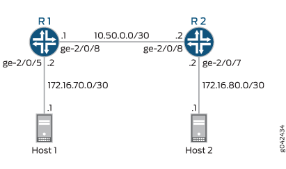
Topology
This example uses the topology in Figure 1.
This video explains the topics used in this example. We recommend that you watch the video before proceeding.
Configuration
Procedure
CLI Quick Configuration
To quickly configure this example,
copy the following commands, paste them into a text file, remove any
line breaks, change any details necessary to match your network configuration,
and then copy and paste the commands into the CLI at the [edit] hierarchy level.
Device R1
set interfaces ge-2/0/5 description to-Host
set interfaces ge-2/0/5 unit 0 family inet address 172.16.70.2/30
set interfaces ge-2/0/5 unit 0 family inet filter input mf-classifier
set interfaces ge-2/0/8 description to-R2
set interfaces ge-2/0/8 unit 0 family inet address 10.50.0.1/30
set interfaces lo0 unit 0 description looback-interface
set interfaces lo0 unit 0 family inet address 192.168.13.1/32
set class-of-service forwarding-classes queue 0 BE-data
set class-of-service forwarding-classes queue 1 Premium-data
set class-of-service forwarding-classes queue 2 voice
set class-of-service forwarding-classes queue 3 NC
set class-of-service interfaces ge-2/0/8 scheduler-map test-map
set class-of-service interfaces ge-2/0/8 unit 0 rewrite-rules dscp IPv4-rewrite-table
set class-of-service rewrite-rules dscp IPv4-rewrite-table forwarding-class BE-data loss-priority low code-point be
set class-of-service rewrite-rules dscp IPv4-rewrite-table forwarding-class Premium-data loss-priority low code-point ef
set class-of-service scheduler-maps test-map forwarding-class BE-data scheduler BE-data
set class-of-service scheduler-maps test-map forwarding-class Premium-data scheduler Prem-data
set class-of-service schedulers BE-data transmit-rate 1m
set class-of-service schedulers BE-data buffer-size percent 25
set class-of-service schedulers BE-data priority low
set class-of-service schedulers Prem-data transmit-rate 1m
set class-of-service schedulers Prem-data buffer-size percent 25
set class-of-service schedulers Prem-data priority high
set firewall family inet filter mf-classifier term BE-data from protocol tcp
set firewall family inet filter mf-classifier term BE-data from port 80
set firewall family inet filter mf-classifier term BE-data then count BE-data
set firewall family inet filter mf-classifier term BE-data then forwarding-class BE-data
set firewall family inet filter mf-classifier term Prem-data from protocol tcp
set firewall family inet filter mf-classifier term Prem-data from port 12345
set firewall family inet filter mf-classifier term Prem-data then count Prem-data
set firewall family inet filter mf-classifier term Prem-data then forwarding-class Premium-data
set firewall family inet filter mf-classifier term accept then accept
set protocols ospf area 0.0.0.0 interface ge-2/0/5.0 passive
set protocols ospf area 0.0.0.0 interface lo0.0 passive
set protocols ospf area 0.0.0.0 interface ge-2/0/8.0
Device R2
set interfaces ge-2/0/7 description to-Host
set interfaces ge-2/0/7 unit 0 family inet address 172.16.80.1/30
set interfaces ge-2/0/8 description to-R1
set interfaces ge-2/0/8 unit 0 family inet address 10.50.0.2/30
set interfaces ge-2/0/8 unit 0 family inet filter input mf-classifier
set interfaces unit 0 description looback-interface
set interfaces unit 0 family inet address 192.168.14.1/32
set firewall family inet filter mf-classifier term BE-data from dscp be
set firewall family inet filter mf-classifier term BE-data then count BE-data
set firewall family inet filter mf-classifier term Premium-data from dscp ef
set firewall family inet filter mf-classifier term Premium-data then count Premium-data
set firewall family inet filter mf-classifier term accept then accept
set protocols ospf area 0.0.0.0 interface ge-2/0/7.0 passive
set protocols ospf area 0.0.0.0 interface lo0.0 passive
set protocols ospf area 0.0.0.0 interface ge-2/0/8.0
Step-by-Step Procedure
The following example requires you to navigate various levels in the configuration hierarchy. For instructions on how to do that, see Using the CLI Editor in Configuration Mode in the Junos OS CLI User Guide.
To configure Device R1:
Configure the device interfaces.
[edit ]
user@R1# set interfaces ge-2/0/5 description to-Host
user@R1# set interfaces ge-2/0/5 unit 0 family inet address 172.16.70.2/30
user@R1# set interfaces ge-2/0/5 unit 0 family inet filter input mf-classifier
user@R1# set interfaces ge-2/0/8 description to-R2
user@R1# set interfaces ge-2/0/8 unit 0 family inet address 10.50.0.1/30
user@R1# set interfaces lo0 unit 0 description looback-interface
user@R1# set interfaces lo0 unit 0 family inet address 192.168.13.1/32
Configure the firewall parameters.
[edit ]
user@R1# set firewall family inet filter mf-classifier term BE-data from protocol tcp
user@R1# set firewall family inet filter mf-classifier term BE-data from port 80
user@R1# set firewall family inet filter mf-classifier term BE-data then count BE-data
user@R1# set firewall family inet filter mf-classifier term BE-data then forwarding-class BE-data
user@R1# set firewall family inet filter mf-classifier term Prem-data from protocol tcp
user@R1# set firewall family inet filter mf-classifier term Prem-data from port 12345
user@R1# set firewall family inet filter mf-classifier term Prem-data then count Prem-data
user@R1# set firewall family inet filter mf-classifier term Prem-data then forwarding-class Premium-data
user@R1# set firewall family inet filter mf-classifier term accept then accept
Configure the class-of-service parameters.
[edit ]
user@R1# set class-of-service forwarding-classes queue 0 BE-data
user@R1# set class-of-service forwarding-classes queue 1 Premium-data
user@R1# set class-of-service forwarding-classes queue 2 voice
user@R1# set class-of-service forwarding-classes queue 3 NC
user@R1# set class-of-service interfaces ge-2/0/8 scheduler-map test-map
user@R1# set class-of-service interfaces ge-2/0/8 unit 0 rewrite-rules dscp IPv4-rewrite-table
user@R1# set class-of-service rewrite-rules dscp IPv4-rewrite-table forwarding-class BE-data loss-priority low code-point be
user@R1# set class-of-service rewrite-rules dscp IPv4-rewrite-table forwarding-class Premium-data loss-priority low code-point ef
user@R1# set class-of-service scheduler-maps test-map forwarding-class BE-data scheduler BE-data
user@R1# set class-of-service scheduler-maps test-map forwarding-class Premium-data scheduler Prem-data
user@R1# set class-of-service schedulers BE-data transmit-rate 1m
user@R1# set class-of-service schedulers BE-data buffer-size percent 25
user@R1# set class-of-service schedulers BE-data priority low
user@R1# set class-of-service schedulers Prem-data transmit-rate 1m
user@R1# set class-of-service schedulers Prem-data buffer-size percent 25
user@R1# set class-of-service schedulers Prem-data priority high
Configure OSPF.
[edit protocols ospf]
user@R1# set area 0.0.0.0 interface ge-2/0/5.0 passive
user@R1# set area 0.0.0.0 interface lo0.0 passive
user@R1# set area 0.0.0.0 interface ge-2/0/8.0
Step-by-Step Procedure
To configure Device R2:
Configure the device interface.
[edit ]
user@R1# set interfaces ge-2/0/7 description to-Host
user@R1# set interfaces ge-2/0/7 unit 0 family inet address 172.16.80.1/30
user@R1# set interfaces ge-2/0/8 description to-R1
user@R1# set interfaces ge-2/0/8 unit 0 family inet address 10.50.0.2/30
user@R2# set interfaces ge-2/0/8 unit 0 family inet filter input mf-classifier
user@R1# set interfaces unit 0 description looback-interface
user@R1# set interfaces unit 0 family inet address 192.168.14.1/32
Configure the firewall parameters.
[edit ]
user@R2# set firewall family inet filter mf-classifier term BE-data from dscp be
user@R2# set firewall family inet filter mf-classifier term BE-data then count BE-data
user@R2# set firewall family inet filter mf-classifier term Premium-data from dscp ef
user@R2# set firewall family inet filter mf-classifier term Premium-data then count Premium-data
user@R2# set firewall family inet filter mf-classifier term accept then accept
Configure OSPF.
[edit protocols ospf]
user@R1# set area 0.0.0.0 interface ge-2/0/7.0 passive
user@R1# set area 0.0.0.0 interface lo0.0 passive
user@R1# set area 0.0.0.0 interface ge-2/0/8.0
Results
From configuration mode, confirm your configuration
by entering the show interfaces, show firewall, show class-of-service , and show protocols ospf commands. If the output does not display the intended configuration,
repeat the instructions in this example to correct the configuration.
user@R1 show interfaces
    ge-2/0/5 {
    description to-Host;
    unit 0 {
        family inet {
            filter {
                input mf-classifier;
            }
            address 172.16.70.2/30;
        }
    }
}
ge-2/0/8 {
    description to-R2;
    unit 0 {
        family inet {
            address 10.50.0.1/30;
        }
    }
}
lo0 {
    unit 0 {
        description looback-interface;
        family inet {
            address 192.168.13.1/32;
        }
    }
}
user@R1 show firewall
family inet {
    filter mf-classifier {
        term BE-data {
            from {
                protocol tcp;
                port 80;
            }
            then {
                count BE-data;
                forwarding-class BE-data;
            }
        }
        term Prem-data {
            from {
                protocol tcp;
                port 12345;
            }
            then {
                count Prem-data;
                forwarding-class Premium-data;
            }
        }
        term accept {
            then accept;
        }
    }
}
user@R1 show class-of-service
forwarding-classes {
    queue 0 BE-data;
    queue 1 Premium-data;
    queue 2 voice;
    queue 3 NC;
}
interfaces {
    ge-2/0/8 {
        scheduler-map test-map;
        unit 0 {
            rewrite-rules {
                dscp IPv4-rewrite-table;
            }
        }
    }
}
rewrite-rules {
    dscp IPv4-rewrite-table {
        forwarding-class BE-data {
            loss-priority low code-point be;
        }
        forwarding-class Premium-data {
            loss-priority low code-point ef;
        }
    }
}
scheduler-maps {
    test-map {
        forwarding-class BE-data scheduler BE-data;
        forwarding-class Premium-data scheduler Prem-data;
    }
}
schedulers {
    BE-data {
        transmit-rate 1m;
        buffer-size percent 25;
        priority low;
    }
    Prem-data {
        transmit-rate 1m;
        buffer-size percent 25;
        priority high;
    }
}
user@R1# show protocols ospf
area 0.0.0.0 {
    interface ge-2/0/5.0 {
        passive;
    }
    interface lo0.0 {
        passive;
    }
    interface ge-2/0/8.0;
}
If you are done configuring Device R1, enter commit from configuration mode.
user@R2# show interfaces
ge-2/0/7 {
    unit 0 {
        description to-Host;
        family inet {
            address 172.16.80.2;
        }
    }
}
ge-2/0/8 {
    description to-R1;
    unit 0 {
        family inet {
            filter {
                input mf-classifier;
            }
            address 10.50.0.2/30;
        }
    }
}
lo0 {
    unit 0 {
        description looback-interface;
        family inet {
            address 192.168.14.1/32;
        }
    }
}
user@R2# show firewall
family inet {
    filter mf-classifier {
        term BE-data {
            from {
                dscp be;
            }
            then count BE-data;
        }
        term Premium-data {
            from {
                dscp ef;
            }
            then count Premium-data;
        }
        term accept {
            then accept;
        }
    }
}
user@R2# show protocols ospf
area 0.0.0.0 {
    interface ge-2/0/7.0 {
        passive;
    }
    interface lo0.0 {
        passive;
    }
    interface ge-2/0/8.0;
}
If you are done configuring Device R2, enter commit from configuration mode.
Verification
Confirm that the configuration is working properly.
- Clearing the Firewall Counters
- Sending Traffic into the Network from TCP HTTP Ports 80 and 12345 and Monitoring the Results
Clearing the Firewall Counters
Purpose
Confirm that the firewall counters are cleared.
Action
On Devices R1 and R2, run the clear firewall all command to reset the firewall counters to 0.
user@R1> clear firewall all
user@R2> clear firewall all
Sending Traffic into the Network from TCP HTTP Ports 80 and 12345 and Monitoring the Results
Purpose
Send traffic from the host connected to Device 1 into the network so that it can be monitored by the firewall on Device R1 and Device R2.
Action
Use a traffic generator to send 20 TCP packets with a source port of 80 into the network.
The -s flag sets the source port. The -k flag causes the source port to remain steady at 80 instead of incrementing. The -c flag sets the number of packets to 20. The -d flag sets the packet size.
[User@host]#  hping 172.16.80.1  -c 20 -s 80  -k -d 300
HPING 172.16.80.1 (eth1 172.16.80.1): NO FLAGS are set, 40 headers + 0 data bytes
len=46 ip=172.16.80.1 ttl=62 DF id=0 sport=0 flags=RA seq=0 win=0 rtt=0.9 ms
.
.
.
--- 172.16.80.1 hping statistic ---
20 packets transmitted, 20 packets received, 0% packet loss
round-trip min/avg/max = 0.9/9501.4/19002.4 ms
Use a traffic generator to send 20 TCP packets with a source port of 12345 into the network.
[User@host]#  hping 172.16.80.1  -c 20 -s 12345  -k -d 300
HPING 172.16.80.1 (eth1 172.16.80.1): NO FLAGS are set, 40 headers + 0 data bytes
len=46 ip=172.16.80.1 ttl=62 DF id=0 sport=0 flags=RA seq=0 win=0 rtt=0.3 ms
.
.
.
--- 172.16.80.1 hping statistic ---
20 packets transmitted, 20 packets received, 0% packet loss
round-trip min/avg/max = 0.3/9501.5/19002.7 ms
On Device R1, check the firewall counters by using the
show firewallcommand.user@R1> show firewall Filter: mf-classifier Counters: Name Bytes Packets BE-data 800 20 Prem-data 800 20
On Device R2, check the firewall counters using the
show firewallcommand.user@R2> show firewall Filter: mf-classifier Counters: Name Bytes Packets BE-data 800 20 Premium-data 800 20
Meaning
Device R1 correctly set the code point for TCP packets to port 12345 to bf. Device R1 correctly set the code point for TCP packets to port 80 to ef. Device R2 correctly recognized the code point for TCP packets to port 12345 as bf. Device R2 correctly recognized the code point for TCP packets to port 80 as ef.