ON THIS PAGE
Example: Remarking Diffserv Code Points to 802.1P PCPs to Carry CoS Profiles Across a Service Provider’s VPLS Network
This configuration example explains how to implement class-of-service (CoS) capabilities over a Virtual Private LAN Service (VPLS) network.
Requirements
To verify this procedure, this example uses a traffic generator. The traffic generator can be hardware-based or it can be software running on a server or host machine.
The functionality in this procedure is widely supported on devices that run Junos OS. The example shown here was tested and verified on MX Series routers running a supported Junos OS release.
Overview
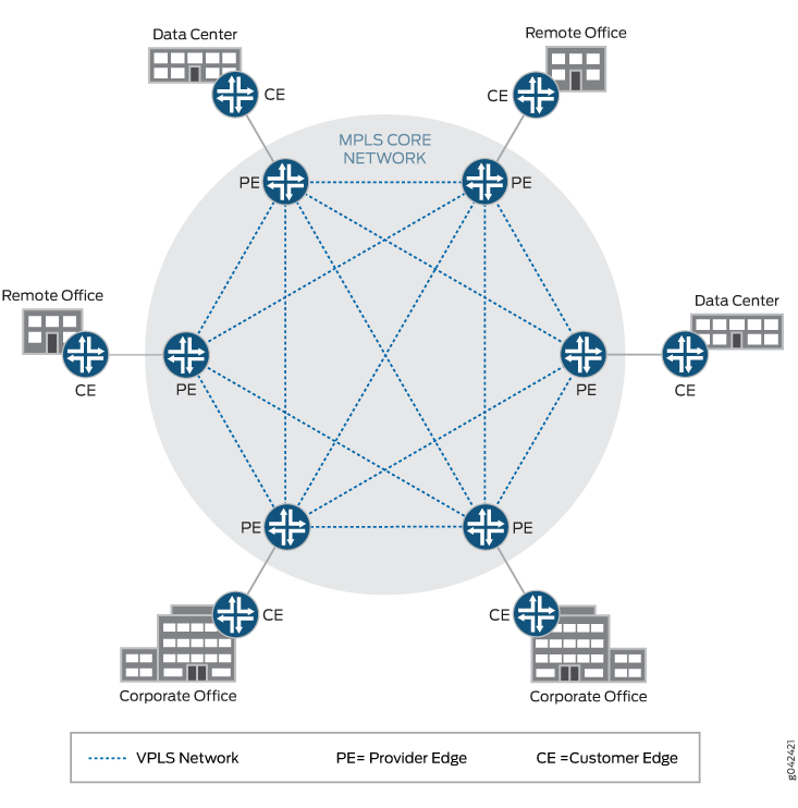
VPLS networks create a Virtual Private LAN that provides a very close approximation of an Ethernet LAN to customers of a service provider. In a VPLS network, it is not necessary for all customers to be connected to a single LAN. Instead, the customers can be spread across two or more LANs. In the simplest sense, a VPLS network connects individual LANs across a packet-switched network so that they appear as a single LAN. See Figure 1 for an example of a typical VPLS topology.
Junos OS contains several DiffServ code point (DSCP) default
rewrite rules that might meet your requirements. You display them
with the show class-of-service rewrite-rule command. A
partial set of the default rewrite DSCP rule mappings is shown in
the following table.
You can also define your own custom rewrite-rules table, or use a mixture of the default rewrite-rules and a custom table that you create. This example uses default rewrite-rules.
|
Map from Forwarding Class |
PLP Value |
MAP to DSCP/DSCP IPv6/EXP/IP Code Point Aliases |
|---|---|---|
|
expedited-forwarding |
low |
ef |
|
expedited-forwarding |
high |
ef |
|
assured-forwarding |
low |
af11 |
|
assured-forwarding |
high |
af12 (DSCP/DSCP IPv6/EXP) |
|
best-effort |
low |
be |
|
best-effort |
high |
be |
|
network-control |
low |
nc1/cs6 |
|
network-control |
high |
nc2/cs7 |
Junos OS uses the values shown in the following table for MPLS CoS in the EXP fields of the MPLS header.
|
Forwarding Class |
Loss Priority |
EXP Code Point |
|---|---|---|
|
best-effort |
low |
000 |
|
best-effort |
high |
001 |
|
expedited-forwarding |
low |
010 |
|
expedited-forwarding |
high |
011 |
|
assured-forwarding |
low |
100 |
|
assured-forwarding |
high |
101 |
|
network-control |
low |
110 |
|
network-control |
high |
111 |
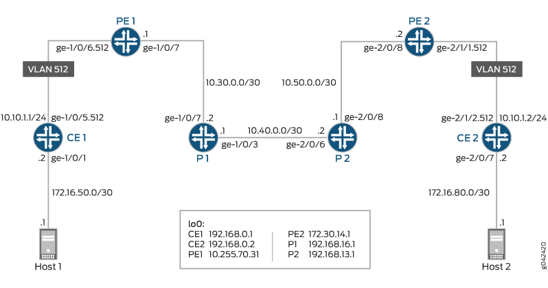
In addition to providing the necessary information to complete the purpose of this example, this example also includes all of the commands required to recreate the VPLS network as shown in Figure 2. A full explanation of the tasks required to configure a VPLS network is not included in this example. If you need more information regarding configuring a VPLS network, see the VPLS User Guide for Routing Devices at http://juniper.net/documentation and RFC 4761 at http://tools.ietf.org/html/rfc4761 .
A thorough explanation of the required CoS tasks and the underlying algorithms used in this example is beyond the scope of this document. For more information, refer to QOS-Enabled Networks—Tools and Foundations by Miguel Barreiros and Peter Lundqvist. This book is available at many online booksellers and at www.juniper.net/books .
Configuration
Procedure
- CLI Quick Configuration
- Step-by-Step Procedure
- Step-by-Step Procedure
- Step-by-Step Procedure
- Step-by-Step Procedure
- Step-by-Step Procedure
- Step-by-Step Procedure
- Results
CLI Quick Configuration
To quickly configure this example,
copy the following commands, paste them into a text file, remove any
line breaks, change any details necessary to match your network configuration,
and then copy and paste the commands into the CLI at the [edit] hierarchy level.
Device CE1
set  interfaces ge-1/0/1 unit 0 description to-Host1
set  interfaces ge-1/0/1 unit 0 family inet address 172.16.50.2/30
set  interfaces ge-1/0/1 unit 0 family inet filter input ip-v4
set interfaces ge-1/0/5 vlan-tagging
set interfaces ge-1/0/5 unit 512 description to_PE1
set interfaces ge-1/0/5 unit 512 vlan-id 512
set interfaces ge-1/0/5 unit 512 family inet address 10.10.1.1/24
set  interfaces lo0 unit 1 description loopback-interface
set  interfaces lo0 unit 1 family inet address 192.168.0.1/32
set  protocols ospf area 0.0.0.0 interface ge-1/0/5.512
set  protocols ospf area 0.0.0.0 interface ge-1/0/1.0 passive
set  protocols ospf area 0.0.0.0 interface lo0.1 passive
set  firewall family inet filter ip-v4 term tcp80 from port 80
set  firewall family inet filter ip-v4 term tcp80 then dscp ef
set  firewall family inet filter ip-v4 term 12345 from port 12345
set  firewall family inet filter ip-v4 term 12345 then dscp be
set  firewall family inet filter ip-v4 term accept then accept
set class-of-service classifiers ieee-802.1 dscp1 forwarding-class expedited-forwarding loss-priority low code-points ef
set class-of-service classifiers ieee-802.1 dscp1 forwarding-class best-effort loss-priority low code-points be
set class-of-service rewrite-rules ieee-802.1 ieee1-c2 forwarding-class expedited-forwarding loss-priority low code-point 010
set class-of-service rewrite-rules ieee-802.1 ieee1-c2 forwarding-class best-effort loss-priority low code-point 000
set class-of-service interfaces ge-1/0/5 unit 512 classifiers ieee-802.1 dscp1
set class-of-service interfaces ge-1/0/5 unit 512 rewrite-rules ieee-802.1 ieee1-c2
Device PE1
set interfaces ge-1/0/6 vlan-tagging
set interfaces ge-1/0/6 encapsulation vlan-vpls
set interfaces ge-1/0/6 unit 512 description to_vpls
set interfaces ge-1/0/6 unit 512 encapsulation vlan-vpls
set interfaces ge-1/0/6 unit 512 vlan-id 512
set interfaces ge-1/0/9 description to_P1
set interfaces ge-1/0/9 unit 0 family inet address 10.30.0.1/30
set interfaces ge-1/0/9 unit 0 family mpls
set interfaces lo0 unit 0 description loopback-interface
set interfaces lo0 unit 0 family inet address 10.255.70.31/32
set protocols mpls interface ge-1/0/9.0
set protocols bgp group to_PE2 type internal
set protocols bgp group to_PE2 local-address 10.255.70.31
set protocols bgp group to_PE2 family l2vpn signaling
set protocols bgp group to_PE2 neighbor 172.30.14.1
set protocols ospf traffic-engineering
set protocols ospf area 0.0.0.0 interface lo0.0 passive
set protocols ospf area 0.0.0.0 interface ge-1/0/9.0
set protocols ldp interface ge-1/0/9.0
set protocols ldp interface lo0.0
set routing-options router-id 10.255.70.31
set routing-options autonomous-system 64511
set routing-instances vpls_a instance-type vpls
set routing-instances vpls_a interface ge-1/0/6.512
set routing-instances vpls_a route-distinguisher 64511:1
set routing-instances vpls_a vrf-target target:64511:1
set routing-instances vpls_a protocols vpls no-tunnel-services
set routing-instances vpls_a protocols vpls site 1 site-identifier 1
set routing-instances vpls_a protocols vpls site 1 interface ge-1/0/6.512
Device P1
set interfaces ge-1/0/3 description to_P2
set interfaces ge-1/0/3 unit 0 family inet address 10.40.0.1/30
set interfaces ge-1/0/3 unit 0 family mpls
set interfaces ge-1/0/9 description to_PE1
set interfaces ge-1/0/9 unit 0 family inet address 10.30.0.2/30
set interfaces ge-1/0/9 unit 0 family mpls
set interfaces lo0 unit 0 description loopback-interface
set interfaces lo0 unit 0 family inet address 192.168.16.1/32
set protocols mpls interface ge-1/0/9.0
set protocols mpls interface ge-1/0/3.0
set protocols ospf traffic-engineering
set protocols ospf area 0.0.0.0 interface ge-1/0/3.0
set protocols ospf area 0.0.0.0 interface ge-1/0/9.0
set protocols ospf area 0.0.0.0 interface lo0.0 passive
set protocols ldp interface ge-1/0/3.0
set protocols ldp interface ge-1/0/9.0
set protocols ldp interface lo0.0
set routing-options router-id 192.168.16.1
Device P2
set interfaces ge-2/0/6 description to_P1
set interfaces ge-2/0/6 unit 0 family inet address 10.40.0.2/30
set interfaces ge-2/0/6 unit 0 family mpls
set interfaces ge-2/0/8 description to_PE2
set interfaces ge-2/0/8 unit 0 family inet address 10.50.0.1/30
set interfaces ge-2/0/8 unit 0 family mpls
set interfaces lo0 unit 0 description loopback-interface
set interfaces lo0 unit 0 family inet address 192.168.13.1/32
set protocols mpls interface ge-2/0/6.0
set protocols mpls interface ge-2/0/8.0
set protocols ospf traffic-engineering
set protocols ospf area 0.0.0.0 interface ge-2/0/6.0
set protocols ospf area 0.0.0.0 interface ge-2/0/8.0
set protocols ospf area 0.0.0.0 interface lo0.0 passive
set protocols ldp interface ge-2/0/6.0
set protocols ldp interface ge-2/0/8.0
set protocols ldp interface lo0.0
set routing-options router-id 192.168.13.1
Device PE2
set interfaces ge-2/0/8 description to-R1
set interfaces ge-2/0/8 unit 0 family inet address 10.50.0.2/30
set interfaces ge-2/0/8 unit 0 family mpls
set interfaces ge-2/1/1 vlan-tagging
set interfaces ge-2/1/1 encapsulation vlan-vpls
set interfaces ge-2/1/1 unit 512 description to_vpls
set interfaces ge-2/1/1 unit 512 encapsulation vlan-vpls
set interfaces ge-2/1/1 unit 512 vlan-id 512
set interfaces lo0 unit 0 description loopback-interface
set interfaces lo0 unit 0 family inet address 172.30.14.1/32
set protocols mpls interface ge-2/0/8.0
set protocols bgp group to_PE1 type internal
set protocols bgp group to_PE1 local-address 172.30.14.1
set protocols bgp group to_PE1 family l2vpn signaling
set protocols bgp group to_PE1 neighbor 10.255.70.31
set protocols ospf traffic-engineering
set protocols ospf area 0.0.0.0 interface ge-2/0/8.0
set protocols ospf area 0.0.0.0 interface lo0.0 passive
set protocols ldp interface ge-2/0/8.0
set protocols ldp interface lo0.0
set routing-options router-id 172.30.14.1
set routing-options autonomous-system 64511
set routing-instances vpls_a instance-type vpls
set routing-instances vpls_a interface ge-2/1/1.512
set routing-instances vpls_a route-distinguisher 64511:1
set routing-instances vpls_a vrf-target target:64511:1
set routing-instances vpls_a protocols vpls no-tunnel-services
set routing-instances vpls_a protocols vpls site 2 site-identifier 2
set routing-instances vpls_a protocols vpls site 2 interface ge-2/1/1.512
Device CE2
set  interfaces ge-2/0/7 unit 0 description to-Host2
set  interfaces ge-2/0/7 unit 0 family inet address 172.16.80.2/30
set  interfaces ge-2/0/7 unit 0 family inet filter input ip-v4
set interfaces ge-2/1/2 vlan-tagging
set interfaces ge-2/1/2 unit 512 description to-PE2
set interfaces ge-2/1/2 unit 512 vlan-id 512
set interfaces ge-2/1/2 unit 512 family inet address 10.10.1.2/24
set  interfaces lo0 unit 1 description loopback-interface
set  interfaces lo0 unit 1 family inet address 192.168.0.2/32
set  protocols ospf area 0.0.0.0 interface lo0.1 passive
set  protocols ospf area 0.0.0.0 interface ge-2/0/7.0 passive
set  protocols ospf area 0.0.0.0 interface ge-2/1/2.512
set  firewall family inet filter ip-v4 term tcp80 from port 80
set  firewall family inet filter ip-v4 term tcp80 then dscp ef
set  firewall family inet filter ip-v4 term 12345 from port 12345
set  firewall family inet filter ip-v4 term 12345 then dscp be
set  firewall family inet filter ip-v4 term accept then accept
set class-of-service classifiers ieee-802.1 dscp1 forwarding-class expedited-forwarding loss-priority low code-points ef
set class-of-service classifiers ieee-802.1 dscp1 forwarding-class best-effort loss-priority low code-points be
set class-of-service rewrite-rules ieee-802.1 ieee1-c2 forwarding-class expedited-forwarding loss-priority low code-point 010
set class-of-service rewrite-rules ieee-802.1 ieee1-c2 forwarding-class best-effort loss-priority low code-point 000
set class-of-service interfaces ge-2/1/2 unit 512 rewrite-rules ieee-802.1 ieee1-c2
set class-of-service interfaces ge-2/1/2 unit 512 classifiers ieee-802.1 dscp1
Step-by-Step Procedure
The following example requires you to navigate various levels in the configuration hierarchy. For information about navigating the CLI, see Using the CLI Editor in Configuration Mode in the Junos OS CLI User Guide.
To configure Device CE1:
-
Configure the device interfaces.
[edit ]
user@CE1# set interfaces ge-1/0/1 unit 0 description to-Host1
user@CE1# set interfaces ge-1/0/1 unit 0 family inet address 172.16.50.2/30
user@CE1#set interfaces ge-1/0/1 unit 0 family inet filter input ip-v4
user@CE1#set interfaces lo0 unit 1 description loopback-interface
user@CE1# set interfaces lo0 unit 1 family inet address 192.168.0.1/32
-
Configure the VLAN parameters.
[edit ]
user@CE1# set interfaces ge-1/0/5 vlan-tagging
user@CE1# set interfaces ge-1/0/5 unit 512 description to_PE1
user@CE1# set interfaces ge-1/0/5 unit 512 vlan-id 512
user@CE1# set interfaces ge-1/0/5 unit 512 family inet address 10.10.1.1/24
-
Configure the class-of-service parameters.
[edit ]
user@CE1# set class-of-service rewrite-rules ieee-802.1 ieee1-c2 forwarding-class expedited-forwarding loss-priority low code-point 010
user@CE1# set class-of-service rewrite-rules ieee-802.1 ieee1-c2 forwarding-class best-effort loss-priority low code-point 000
user@CE1# set class-of-service classifiers ieee-802.1 dscp1 forwarding-class expedited-forwarding loss-priority low code-points ef
user@CE1# set class-of-service classifiers ieee-802.1 dscp1 forwarding-class best-effort loss-priority low code-points be
user@CE1# set class-of-service interfaces ge-1/0/5 unit 512 rewrite-rules ieee-802.1 ieee1-c2
user@CE1# set class-of-service interfaces ge-1/0/5 unit 512 classifiers ieee-802.1 dscp1
-
Configure the protocol parameters.
[edit ]
user@CE1# set protocols ospf area 0.0.0.0 interface ge-1/0/5.512
user@CE1# set protocols ospf area 0.0.0.0 interface ge-1/0/1.0 passive
user@CE1# set protocols ospf area 0.0.0.0 interface lo0.0 passive
-
Configure the firewall DSCP rewrite parameters.
[edit ]
user@CE1# set firewall family inet filter ip-v4 term tcp80 from port 80
user@CE1# set firewall family inet filter ip-v4 term tcp80 then dscp ef
user@CE1# set firewall family inet filter ip-v4 term 12345 from port 12345
user@CE1# set firewall family inet filter ip-v4 term 12345 then dscp be
user@CE1# set firewall family inet filter ip-v4 term accept then accept
Step-by-Step Procedure
To configure Device PE1:
-
Configure the device interfaces.
[edit ]
user@PE1# set interfaces ge-1/0/9 description to_P1
user@PE1# set interfaces ge-1/0/9 unit 0 family inet address 10.30.0.1/30
user@PE1# set interfaces ge-1/0/9 unit 0 family mpls
user@PE1# set interfaces lo0 unit 0 description loopback-interface
user@PE1# set interfaces lo0 unit 0 family inet address 10.255.70.31/32
-
Configure the VLAN parameters.
[edit ]
user@PE1# set interfaces ge-1/0/6 vlan-tagging
user@PE1# set interfaces ge-1/0/6 encapsulation vlan-vpls
user@PE1# set interfaces ge-1/0/6 unit 512 description to_vpls
user@PE1# set interfaces ge-1/0/6 unit 512 encapsulation vlan-vpls
user@PE1# set interfaces ge-1/0/6 unit 512 vlan-id 512
-
Configure the protocol parameters.
[edit ]
user@PE1# set protocols mpls interface ge-1/0/9.0
user@PE1# set protocols bgp group to_PE2 type internal
user@PE1# set protocols bgp group to_PE2 local-address 10.255.70.31
user@PE1# set protocols bgp group to_PE2 family l2vpn signaling
user@PE1# set protocols bgp group to_PE2 neighbor 172.30.14.1
user@PE1# set protocols ospf traffic-engineering
user@PE1# set protocols ospf area 0.0.0.0 interface lo0.0 passive
user@PE1# set protocols ospf area 0.0.0.0 interface ge-1/0/9.0
user@PE1# set protocols ldp interface ge-1/0/9.0
user@PE1# set protocols ldp interface lo0.0
-
Configure the routing option parameters.
[edit ]
user@PE1# set routing-options router-id 10.255.70.31
user@PE1# set routing-options autonomous-system 64511
-
Configure the routing instance parameters.
[edit ]
user@PE1# set routing-instances vpls_a instance-type vpls
user@PE1# set routing-instances vpls_a interface ge-1/0/6.512
user@PE1# set routing-instances vpls_a route-distinguisher 64511:1
user@PE1# set routing-instances vpls_a vrf-target target:64511:1
user@PE1# set routing-instances vpls_a protocols vpls no-tunnel-services
user@PE1# set routing-instances vpls_a protocols vpls site 1 site-identifier 1
user@PE1# set routing-instances vpls_a protocols vpls site 1 interface ge-1/0/6.512
Step-by-Step Procedure
To configure Device P1:
-
Configure the device interfaces.
[edit ]
user@P1# set interfaces ge-1/0/3 description to_P2
user@P1# set interfaces ge-1/0/3 unit 0 family inet address 10.40.0.1/30
user@P1# set interfaces ge-1/0/3 unit 0 family mpls
user@P1# set interfaces ge-1/0/9 description to_PE1
user@P1# set interfaces ge-1/0/9 unit 0 family inet address 10.30.0.2/30
user@P1# set interfaces ge-1/0/9 unit 0 family mpls
user@P1# set interfaces lo0 unit 0 description loopback-interface
user@P1# set interfaces lo0 unit 0 family inet address 192.168.16.1/32
-
Configure the protocol parameters.
[edit ]
user@P1# set protocols mpls interface ge-1/0/9.0
user@P1# set protocols mpls interface ge-1/0/3.0
user@P1# set protocols ospf traffic-engineering
user@P1# set protocols ospf area 0.0.0.0 interface ge-1/0/3.0
user@P1# set protocols ospf area 0.0.0.0 interface ge-1/0/9.0
user@P1# set protocols ospf area 0.0.0.0 interface lo0.0 passive
user@P1# set protocols ldp interface ge-1/0/3.0
user@P1# set protocols ldp interface ge-1/0/9.0
user@P1# set protocols ldp interface lo0.0
-
Configure the routing options parameter.
[edit ]
user@P1# set routing-options router-id 192.168.16.1
Step-by-Step Procedure
To configure Device P2:
-
Configure the device interfaces.
[edit ]
user@P2# set interfaces ge-2/0/6 description to_P1
user@P2#set interfaces ge-2/0/6 unit 0 family inet address 10.40.0.2/30
user@P2# set interfaces ge-2/0/6 unit 0 family mpls
user@P2# set interfaces ge-2/0/8 description to_PE2
user@P2# set interfaces ge-2/0/8 unit 0 family inet address 10.50.0.1/30
user@P2# set interfaces ge-2/0/8 unit 0 family mpls
user@P2# set interfaces lo0 unit 0 description loopback-interface
user@P2# set interfaces lo0 unit 0 family inet address 192.168.13.1/32
-
Configure the protocol parameters.
[edit ]
user@P2# set protocols mpls interface ge-2/0/6.0
user@P2# set protocols mpls interface ge-2/0/8.0
user@P2# set protocols ospf traffic-engineering
user@P2#  set protocols ospf area 0.0.0.0 interface ge-2/0/6.0
user@P2# set protocols ospf area 0.0.0.0 interface ge-2/0/8.0
user@P2# set protocols ospf area 0.0.0.0 interface lo0.0 passive
user@P2# set protocols ldp interface ge-2/0/6.0
user@P2# set protocols ldp interface ge-2/0/8.0
user@P2# set protocols ldp interface lo0.0
-
Configure the routing option parameter.
[edit ]
user@P2# set routing-options router-id 192.168.13.1
Step-by-Step Procedure
To configure Device PE2:
-
Configure the device interfaces.
[edit ]
user@PE2# set interfaces ge-2/0/8 description to-R1
user@PE2# set interfaces ge-2/0/8 unit 0 family inet address 10.50.0.2/30
user@PE2# set interfaces ge-2/0/8 unit 0 family mpls
user@PE2# set interfaces lo0 unit 0 description loopback-interface
user@PE2# set interfaces lo0 unit 0 family inet address 172.30.14.1/32
-
Configure the VLAN parameters.
[edit ]
user@PE2# set interfaces ge-2/1/1 vlan-tagging
user@PE2# set interfaces ge-2/1/1 encapsulation vlan-vpls
user@PE2# set interfaces ge-2/1/1 unit 512 description to_vpls
user@PE2# set interfaces ge-2/1/1 unit 512 encapsulation vlan-vpls
user@PE2# set interfaces ge-2/1/1 unit 512 vlan-id 512
-
Configure the protocol parameters.
[edit ]
user@PE2# set protocols mpls interface ge-2/0/8.0
user@PE2# set protocols bgp group to_PE1 type internal
user@PE2# set protocols bgp group to_PE1 local-address 172.30.14.1
user@P2# set protocols bgp group to_PE1 family l2vpn signaling
user@PE2# set protocols bgp group to_PE1 neighbor 10.255.70.31
user@PE2# set protocols ospf traffic-engineering
user@PE2# set protocols ospf area 0.0.0.0 interface ge-2/0/8.0
user@PE2# set protocols ospf area 0.0.0.0 interface lo0.0 passive
user@PE2# set protocols ldp interface ge-2/0/8.0
user@PE2# set protocols ldp interface lo0.0
-
Configure the routing option parameters.
[edit ]
user@PE2# set routing-options router-id 172.30.14.1
user@PE2# set routing-options autonomous-system 64511
-
Configure the routing instance parameters.
[edit ]
user@P2# set routing-instances vpls_a instance-type vpls
user@PE2# set routing-instances vpls_a interface ge-2/1/1.512
user@PE2# set routing-instances vpls_a route-distinguisher 64511:1
user@PE2# set routing-instances vpls_a vrf-target target:64511:1
user@PE2# set routing-instances vpls_a protocols vpls no-tunnel-services
user@PE2# set routing-instances vpls_a protocols vpls site 2 site-identifier 2
user@PE2# set routing-instances vpls_a protocols vpls site 2 interface ge-2/1/1.512
Step-by-Step Procedure
To configure Device CE2:
-
Configure the device interfaces.
[edit ]
user@CE2# set interfaces ge-2/0/7 unit 0 description to-Host2
user@CE2# set interfaces ge-2/0/7 unit 0 family inet address 172.16.80.2/30
user@CE2# set interfaces ge-2/0/7 unit 0 family inet filter input ip-v4
user@CE2# set interfaces lo0 unit 1 description loopback-interface
user@CE2# set interfaces lo0 unit 1 family inet address 192.168.0.2/32
-
Configure the VLAN parameters
[edit ]
user@CE2# set interfaces ge-2/1/2 vlan-tagging
user@CE2# set interfaces ge-2/1/2 unit 512 description to-PE2
user@CE2# set interfaces ge-2/1/2 unit 512 vlan-id 512
user@CE2# set interfaces ge-2/1/2 unit 512 family inet address 10.10.1.2/24
-
Configure the class-of-service parameters.
[edit ]
user@CE2# set class-of-service rewrite-rules ieee-802.1 ieee1-c2 forwarding-class expedited-forwarding loss-priority low code-point 010
user@CE2# set class-of-service rewrite-rules ieee-802.1 ieee1-c2 forwarding-class best-effort loss-priority low code-point 000
user@CE2# set class-of-service classifiers ieee-802.1 dscp1 forwarding-class expedited-forwarding loss-priority low code-points ef
user@CE2# set class-of-service classifiers ieee-802.1 dscp1 forwarding-class best-effort loss-priority low code-points be
user@CE2# set class-of-service interfaces ge-2/1/2 unit 512 rewrite-rules ieee-802.1 ieee1-c2
user@CE2# set class-of-service interfaces ge-2/1/2 unit 512 classifiers ieee-802.1 dscp1
-
Configure the protocol parameters.
[edit ]
user@CE2# set protocols ospf area 0.0.0.0 interface lo0.0 passive
user@CE2# set protocols ospf area 0.0.0.0 interface ge-2/0/7.0 passive
user@CE2# set protocols ospf area 0.0.0.0 interface ge-2/1/2.512
-
Configure the firewall DSCP rewrite parameters.
[edit ]
user@CE2# set firewall family inet filter ip-v4 term tcp80 from port 80
user@CE2# set firewall family inet filter ip-v4 term tcp80 then dscp ef
user@CE2# set firewall family inet filter ip-v4 term 12345 from port 12345
user@CE2# set firewall family inet filter ip-v4 term 12345 then dscp be
user@CE2# set firewall family inet filter ip-v4 term accept then accept
Results
From configuration mode, confirm your configuration
by entering the show interfaces, show class-of-service, show protocols, show routing-options, show
routing-instances, and show firewall, commands.
If the output does not display the intended configuration, repeat
the instructions in this example to correct the configuration.
user@CE1# show interfaces
ge-1/0/1 {
    unit 0 {
        description to-Host1;
        family inet {
            filter {
                input ip-v4;
            }
            address 172.16.50.2/30;
        }
    }
}
ge-1/0/5 {
    vlan-tagging;
    unit 512 {
        description to_PE1;
        vlan-id 512;
        family inet {
            address 10.10.1.1/24;
        }
    }
}
lo0 {
    unit 1 {
        description loopback-interface;
        family inet {
            address 192.168.0.1/32;
        }
    }
}
user@CE1# show class-of-service
classifiers {
    ieee-802.1 dscp1 {
        forwarding-class expedited-forwarding {
            loss-priority low code-points ef;
        }
        forwarding-class best-effort {
            loss-priority low code-points be;
        }
    }
}
interfaces {
    ge-1/0/5 {
        unit 512 {
            classifiers {
                ieee-802.1 dscp1;
            }
            rewrite-rules {
                ieee-802.1 ieee1-c2;
            }
        }
    }
}
rewrite-rules {
    ieee-802.1 ieee1-c2 {
        forwarding-class expedited-forwarding {
            loss-priority low code-point 010;
        }
        forwarding-class best-effort {
            loss-priority low code-point 000;
        }
    }
}
user@CE1# show protocols
ospf {
    area 0.0.0.0 {
        interface ge-1/0/5.512;
        interface ge-1/0/1.0 {
            passive;
        }
        interface lo0.1 {
            passive;
        }
    }
}
user@CE1# show firewall
family inet {
    filter ip-v4 {
        term tcp80 {
            from {
                port 80;
            }
            then dscp ef;
        }
        term 12345 {
            from {
                port 12345;
            }
            then dscp be;
        }
        term accept {
            then accept;
        }
    }
}
If you are done configuring Device CE1, enter commit from configuration mode.
user@PE1# show interfaces
ge-1/0/6 {
    vlan-tagging;
    encapsulation vlan-vpls;
    unit 512 {
        description to_vpls;
        encapsulation vlan-vpls;
        vlan-id 512;
    }
}
ge-1/0/9 {
    description to_P1;
    unit 0 {
        family inet {
            address 10.30.0.1/30;
        }
        family mpls;
    }
}
lo0 {
    unit 0 {
        description loopback-interface;
        family inet {
            address 10.255.70.31/32;
        }
    }
}
user@PE1# show protocols
mpls {
    interface ge-1/0/9.0;
}
bgp {
    group to_PE2 {
        type internal;
        local-address 10.255.70.31;
        family l2vpn {
            signaling;
        }
        neighbor 172.30.14.1;
    }
}
ospf {
    traffic-engineering;
    area 0.0.0.0 {
        interface lo0.0 {
            passive;
        }
        interface ge-1/0/9.0;
    }
}
ldp {
    interface ge-1/0/9.0;
    interface lo0.0;
}
user@PE1# show routing-options
router-id 10.255.70.31;
autonomous-system 64511;
user@PE1# show routing-instances
vpls_a {
    instance-type vpls;
    interface ge-1/0/6.512;
    route-distinguisher 64511:1;
    vrf-target target:64511:1;
    protocols {
        vpls {
            no-tunnel-services;
            site 1 {
                site-identifier 1;
                interface ge-1/0/6.512;
            }
        }
    }
}
If you are done configuring Device PE1, enter commit from configuration mode.
user@P1# show interfaces
ge-1/0/3 {
    description to_P2;
    unit 0 {
        family inet {
            address 10.40.0.1/30;
        }
        family mpls;
    }
}
ge-1/0/9 {
    description to_PE1;
    unit 0 {
        family inet {
            address 10.30.0.2/30;
        }
        family mpls;
    }
}
lo0 {
    unit 0 {
        description loopback-interface;
        family inet {
            address 192.168.16.1/32;
        }
    }
}
lo0 {
    unit 0 {
        description loopback-interface;
        family inet {
            address 192.168.16.1/32;
        }
    }
}
user@P1# show protocols
mpls {
    interface ge-1/0/9.0;
    interface ge-1/0/3.0;
}
ospf {
    traffic-engineering;
    area 0.0.0.0 {
        interface ge-1/0/3.0;
        interface ge-1/0/9.0;
        interface lo0.0 {
            passive;
        }
    }
}
ldp {
    interface ge-1/0/3.0;
    interface ge-1/0/9.0;
    interface lo0.0;
}
user@P1# show routing-options
router-id 192.168.16.1;
If you are done configuring Device P1, enter commit from configuration mode.
user@P2# show interfaces
ge-2/0/6 {
    description to_P1;
    unit 0 {
        family inet {
            address 10.40.0.2/30;
        }
        family mpls;
    }
}
ge-2/0/8 {
    description to_PE2;
    unit 0 {
        family inet {
            address 10.50.0.1/30;
        }
        family mpls;
    }
}
lo0 {
    unit 0 {
        description loopback-interface;
        family inet {
            address 192.168.13.1/32;
        }
    }
}
user@P2# show protocols
mpls {
    interface ge-2/0/6.0;
    interface ge-2/0/8.0;
}
ospf {
    traffic-engineering;
    area 0.0.0.0 {
        interface ge-2/0/6.0;
        interface ge-2/0/8.0;
        interface lo0.0 {
            passive;
        }
    }
}
ldp {
    interface ge-2/0/6.0;
    interface ge-2/0/8.0;
    interface lo0.0;
}
user@P2# show routing-options
router-id 192.168.13.1;
If you are done configuring Device P2, enter commit from configuration mode.
user@PE2# show interfaces
ge-2/0/8 {
    description to-R1;
    unit 0 {
        family inet {
            address 10.50.0.2/30;
        }
        family mpls;
    }
}
ge-2/1/1 {
    vlan-tagging;
    encapsulation vlan-vpls;
    unit 512 {
        description to_vpls;
        encapsulation vlan-vpls;
        vlan-id 512;
    }
}
lo0 {
    unit 0 {
        description loopback-interface;
        family inet {
            address 172.30.14.1/32;
        }
    }
}
user@PE2# show protocols
mpls {
    interface ge-2/0/8.0;
}
bgp {
    group to_PE1 {
        type internal;
        local-address 172.30.14.1;
        family l2vpn {
            signaling;
        }
        neighbor 10.255.70.31;
    }
}
ospf {
    traffic-engineering;
    area 0.0.0.0 {
        interface ge-2/0/8.0;
        interface lo0.0 {
            passive;
        }
    }
}
ldp {
    interface ge-2/0/8.0;
    interface lo0.0;
}
user@PE2# show routing-options
router-id 172.30.14.1;
autonomous-system 64511;
user@PE2# show routing-instances
vpls_a {
    instance-type vpls;
    interface ge-2/1/1.512;
    route-distinguisher 64511:1;
    vrf-target target:64511:1;
    protocols {
        vpls {
            no-tunnel-services;
            site 2 {
                site-identifier 2;
                interface ge-2/1/1.512;
            }
        }
    }
}
If you are done configuring Device PE2, enter commit from configuration mode.
user@CE2# show interfaces
ge-2/0/7 {
    unit 0 {
        description to-Host2;
        family inet {
            filter {
                input ip-v4;
            }
            address 172.16.80.2/30;
        }
    }
}
ge-2/1/2 {
    vlan-tagging;
    unit 512 {
        description to-PE2;
        vlan-id 512;
        family inet {
            address 10.10.1.2/24;
        }
    }
}
lo0 {
    unit 1 {
        description loopback-interface;
        family inet {
            address 192.168.0.2/32;
        }
    }
}
user@CE2# show class-of-service
classifiers {
    ieee-802.1 dscp1 {
        forwarding-class expedited-forwarding {
            loss-priority low code-points ef;
        }
        forwarding-class best-effort {
            loss-priority low code-points be;
        }
    }
}
interfaces {
    ge-2/1/2 {
        unit 512 {
            classifiers {
                ieee-802.1 dscp1;
            }
            rewrite-rules {
                ieee-802.1 ieee1-c2;
            }
        }
    }
}
rewrite-rules {
    ieee-802.1 ieee1-c2 {
        forwarding-class expedited-forwarding {
            loss-priority low code-point 010;
        }
        forwarding-class best-effort {
            loss-priority low code-point 000;
        }
    }
}
user@CE2# show protocols
ospf {
    area 0.0.0.0 {
        interface lo0.1 {
            passive;
        }
        interface ge-2/0/7.0 {
            passive;
        }
        interface ge-2/1/2.512;
    }
}
user@CE2# show firewall
family inet {
    filter ip-v4 {
        term tcp80 {
            from {
                port 80;
            }
            then dscp ef;
        }
        term 12345 {
            from {
                port 12345;
            }
            then dscp be;
        }
        term accept {
            then accept;
        }
    }
}
If you are done configuring Device CE2, enter commit from configuration mode.
Verification
Confirm that the configuration is working properly by verifying that the DSCP aliases are maintained from Device CE1 to Device CE2.
- Clearing the Firewall Counters
- Sending Traffic into the Network from TCP HTTP Ports 80 and 12345 and Verifying the Results
Clearing the Firewall Counters
Purpose
Confirm that the firewall counters are cleared.
Action
On Device CE2, run the clear firewall all command to reset the firewall counters to 0.
user@CE2> clear firewall all
Sending Traffic into the Network from TCP HTTP Ports 80 and 12345 and Verifying the Results
Purpose
Send traffic into the network that can be verified at Device CE2.
Action
Configure a new firewall on Device CE2 if you want to verify that the traffic that is being transmitted to Device Host2 from Device Host1 still has the correct DSCP aliases. The following commands create and apply the firewall filter that displays the traffic counts for each code point alias:
user@CE2# set firewall family inet filter count term be from dscp be
user@CE2# set firewall family inet filter count term be then count be
user@CE2# set firewall family inet filter count term ef from dscp ef
user@CE2# set firewall family inet filter count term ef then count ef
user@CE2# set firewall family inet filter count term accept then accept
user@CE2# set interfaces ge-2/0/7 unit 0 family inet filter output count
When you are done configuring Device CE2, enter commit from configuration mode.
When you are done testing, you can leave the counting filter in place, or remove it.
-
On Device Host1 use a traffic generator to send 20 TCP packets with a source port of 80 into the network.
The -s flag sets the source port. The -k flag causes the source port to remain steady instead of incrementing. The -c flag sets the number of packets to 20.
Repeat the task using a source port of 12345.
[user@host1]#  hping 172.16.80.1  -s 80  -k -c 20
[user@host1]#  hping 172.16.80.1  -s 12345  -k -c 20
-
On Device CE2, display the firewall counters by using the
show firewallcommand.user@CE2> show firewall show firewall Filter: __CE2/count Counters: Name Bytes Packets be 800 20 ef 800 20
Meaning
The code point aliases set by Device CE1 are maintained across the VPLS backbone and appear intact at Device CE2.