CoS Explicit Congestion Notification (ECN)
Use ECN to improve transport efficiency between two IP endpoints by marking packets to signal congestion instead of dropping them.
Overview
Explicit congestion notification (ECN) enables end-to-end congestion notification between two endpoints on IP based networks. ECN improves transport efficiency between two IP endpoints by marking packets to signal congestion instead of dropping them for RED (random early detection). The two endpoints are an ECN-enabled sender and an ECN-enabled receiver. ECN must be enabled on both endpoints and on all of the intermediate devices between the endpoints for ECN to work properly. Any device in the transmission path that does not support ECN breaks the end-to-end ECN functionality.
ECN marking happens at the IP header level. ECN works well with both TCP and UDP/ROCEv2 traffic.
ECN notifies networks about congestion with the goal of reducing packet loss and delay by making the sending device decrease the transmission rate until the congestion clears, without dropping packets. RFC 3168, The Addition of Explicit Congestion Notification (ECN) to IP, defines ECN.
ECN is disabled by default. You can enable ECN on any queue and the transport protocol chooses whether to use it. Normally, you enable ECN only on queues that handle best-effort traffic because other traffic types use different methods of congestion notification—lossless traffic uses priority-based flow control (PFC) and strict-high priority traffic receives all of the port bandwidth it requires up to the point of a configured maximum rate.
You enable ECN on individual output queues (as represented by forwarding classes) by enabling ECN in the queue scheduler configuration, mapping the scheduler to forwarding classes (queues), and then applying the scheduler to interfaces.
There are two types of ECN: Static ECN and Dynamic ECN (D-ECN). Static ECN requires you to manually configure the thresholds that trigger congestion notifications, and the thresholds stay the same until you change the setting. Dynamic ECN adjusts the thresholds automatically based on real-time conditions such as queue length and traffic patterns.
On supported devices, both ECN versions can be enabled on your device at the same time, but only one version can be assigned to a particular queue at a time.
For ECN to work on a queue, you must also apply a weighted random early detection (WRED) packet drop profile to the queue.
How ECN Works
Without ECN, devices respond to network congestion by dropping IP packets. Dropped packets signal the network that congestion is occurring. Devices on the IP network respond to packet drops by reducing the packet transmission rate to allow the congestion to clear. However, the packet drop method of congestion notification and management has some disadvantages. For example, packets are dropped and must be retransmitted. Also, bursty traffic can cause the network to reduce the transmission rate too much, resulting in inefficient bandwidth utilization.
Instead of dropping packets to signal network congestion, ECN marks packets to signal network congestion, without dropping the packets. For ECN to work, all of the devices in the path between two ECN-enabled endpoints must have ECN enabled. ECN is negotiated during the establishment of the connection between the endpoints.
ECN-enabled devices determine the queue congestion state based on the WRED packet drop profile configuration applied to the queue, so each ECN-enabled queue must also have a WRED drop profile. If a queue fills to the level at which the WRED drop profile has a packet drop probability greater than zero (0), the device might mark a packet as experiencing congestion. Whether or not a device marks a packet as experiencing congestion is the same probability as the drop probability of the queue at that fill level.
ECN communicates whether or not congestion is experienced by marking the two least-significant bits in the differentiated services (DiffServ) field in the IP header. The most significant six bits in the DiffServ field contain the Differentiated Services Code Point (DSCP) bits. The state of the two ECN bits signals whether or not the packet is an ECN-capable packet and whether or not congestion has been experienced.
ECN-capable senders mark packets as ECN-capable. If a sender is not ECN-capable, it marks packets as not ECN-capable. If an ECN-capable packet experiences congestion at the egress queue of a device, the device marks the packet as experiencing congestion. When the packet reaches the ECN-capable receiver (destination endpoint), the receiver echoes the congestion indicator to the sender (source endpoint) by sending a packet marked to indicate congestion.
After receiving the congestion indicator from the receiver, the source endpoint reduces the transmission rate to relieve the congestion. This is similar to the result of TCP congestion notification and management, but instead of dropping the packet to signal network congestion, ECN marks the packet and the receiver echoes the congestion notification to the sender. Because the packet is not dropped, the packet does not need to be retransmitted.
- ECN Bits in the DiffServ Field
- End-to-End ECN Behavior
- End-to-end ECN Behavior
- ECN Compared to PFC and Ethernet PAUSE
ECN Bits in the DiffServ Field
The two ECN bits in the DiffServ field provide four codes that determine if a packet is marked as an ECN-capable transport (ECT) packet, meaning that both endpoints of the transport protocol are ECN-capable, and if there is congestion experienced (CE), as shown in the table below:
ECN Bits (Code) |
Meaning |
|---|---|
00 |
Non-ECT—Packet is marked as not ECN-capable |
01 |
ECT(1)—Endpoints of the transport protocol are ECN-capable |
10 |
ECT(0)—Endpoints of the transport protocol are ECN-capable |
11 |
CE—Congestion experienced |
Codes 01 and 10 have the same meaning: the sending and receiving endpoints of the transport protocol are ECN-capable. There is no difference between these codes.
End-to-End ECN Behavior
After the sending and receiving endpoints negotiate ECN, the sending endpoint marks packets as ECN-capable by setting the DiffServ ECN field to ECT(1) (01) or ECT(0) (10). Every intermediate device between the endpoints must have ECN enabled or it does not work.
When a packet traverses a device and experiences congestion at an output queue that uses the WRED packet drop mechanism, the device marks the packet as experiencing congestion by setting the DiffServ ECN field to CE (11). Instead of dropping the packet (as with TCP congestion notification), the device forwards the packet.
At the egress queue, the WRED algorithm determines whether or not a packet is drop eligible based on the queue fill level (how full the queue is). If a packet is drop eligible and marked as ECN-capable, the packet can be marked CE and forwarded. If a packet is drop eligible and is not marked as ECN-capable, it might be dropped. See WRED Drop Profile Control of ECN Thresholds for more information about the WRED algorithm.
When the packet reaches the receiver endpoint, the CE mark tells the receiver that there is network congestion. The receiver then sends (echoes) a message to the sender that indicates there is congestion on the network. The sender acknowledges the congestion notification message and reduces its transmission rate. The diagram below summarizes how ECN works to mitigate network congestion:
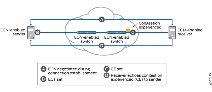
End-to-end ECN Behavior
End-to-end ECN behavior includes:
The ECN-capable sender and receiver negotiate ECN capability during the establishment of their connection.
After successful negotiation of ECN capability, the ECN-capable sender sends IP packets with the ECT field set to the receiver.
Note:You must enable ECN on all of the intermediate devices in the path between the sender and the receiver.
If the WRED algorithm on a device egress queue determines that the queue is experiencing congestion and the packet is drop eligible, the device can mark the packet as “congestion experienced” (CE) to indicate to the receiver that there is congestion on the network. If the packet has already been marked CE (congestion has already been experienced at the egress of another device), the device forwards the packet with CE marked.
If there is no congestion at the egress queue, the device forwards the packet and does not change the ECT-enabled marking of the ECN bits, so the packet is still marked as ECN-capable but not as experiencing congestion.
The receiver receives a packet marked CE to indicate that congestion was experienced along the congestion path.
The receiver echoes (sends) a packet back to the sender with the ECE bit (bit 9) marked in the flag field of the TCP/UDP header. The ECE bit is the ECN echo flag bit, which notifies the sender that there is congestion on the network.
The sender reduces the data transmission rate and sends a packet to the receiver with the CWR bit (bit 8) marked in the flag field of the TCP/UDP header. The CWR bit is the congestion window reduced flag bit, which acknowledges to the receiver that the congestion experienced notification was received.
When the receiver receives the CWR flag, the receiver stops setting the ECE bit in replies to the sender.
The table below summarizes the behavior of traffic on ECN-enabled queues.
Incoming IP Packet Marking of ECN Bits |
ECN Configuration on the Output Queue |
Action if WRED Algorithm Determines Packet is Drop Eligible |
Outgoing Packet Marking of ECN Bits |
|---|---|---|---|
Non-ECT (00) |
Does not matter |
Drop. |
No ECN bits marked |
ECT (10 or 01) |
ECN disabled |
Drop |
Packet dropped—no ECN bits marked |
ECT (10 or 01) |
ECN enabled |
Do not drop. Mark packet as experiencing congestion (CE, bits 11). |
Packet marked ECT (11) to indicate congestion |
CE (11) |
ECN disabled |
Drop |
Packet dropped—no ECN bits marked |
CE (11) |
ECN enabled |
Do not drop. Packet is already marked as experiencing congestion, forward packet without changing the ECN marking. |
Packet marked ECT (11) to indicate congestion |
When an output queue is not experiencing congestion as defined by the WRED drop profile mapped to the queue, all packets are forwarded, and no packets are dropped.
ECN Compared to PFC and Ethernet PAUSE
ECN is an end-to-end network congestion notification mechanism for IP traffic. Priority-based flow control (PFC) (IEEE 802.1Qbb) and Ethernet PAUSE (IEEE 802.3X) are different types of congestion management mechanisms.
ECN requires that an output queue must also have an associated WRED packet drop profile. Output queues used for traffic on which PFC is enabled should not have an associated WRED drop profile. Interfaces on which Ethernet PAUSE is enabled should not have an associated WRED drop profile.
PFC is a peer-to-peer flow control mechanism to support lossless traffic. PFC enables connected peer devices to pause flow transmission during periods of congestion. PFC enables you to pause traffic on a specified type of flow on a link instead of on all traffic on a link. For example, you can (and should) enable PFC on lossless traffic classes such as the fcoe forwarding class. Ethernet PAUSE is also a peer-to-peer flow control mechanism, but instead of pausing only specified traffic flows, Ethernet PAUSE pauses all traffic on a physical link.
With PFC and Ethernet PAUSE, the sending and receiving endpoints of a flow do not communicate congestion information to each other across the intermediate devices. Instead, PFC controls flows between two PFC-enabled peer devices (for example, devices) that support data center bridging (DCB) standards. PFC works by sending a pause message to the connected peer when the flow output queue becomes congested. Ethernet PAUSE simply pauses all traffic on a link during periods of congestion and does not require DCB.
PFC works this way: if a device output queue fills to a certain threshold, the device sends a PFC pause message to the connected peer device that is transmitting data. The pause message tells the transmitting device to pause transmission of the flow. When the congestion clears, the device sends another PFC message to tell the connected peer to resume transmission. (If the output queue of the transmitting device also reaches a certain threshold, that device can in turn send a PFC pause message to the connected peer that is transmitting to it. In this way, PFC can propagate a transmission pause back through the network.)
See Understanding CoS Flow Control (Ethernet PAUSE and PFC) for more information. You can also refer to Understanding PFC Functionality Across Layer 3 Interfaces.
WRED Drop Profile Control of ECN Thresholds
You apply WRED drop profiles to forwarding classes (which are mapped to output queues) to control how the device marks ECN-capable packets. A scheduler map associates a drop profile with a scheduler and a forwarding class, and then you apply the scheduler map to interfaces to implement the scheduling properties for the forwarding class on those interfaces.
Drop profiles define queue fill level (the percentage of queue fullness) and drop probability (the percentage probability that a packet is dropped) pairs. When a queue fills to a specified level, traffic that matches the drop profile has the drop probability paired with that fill level. When you configure a drop profile, you configure pairs of fill levels and drop probabilities to control how packets drop at different levels of queue fullness.
The first fill level and drop probability pair is the drop start point. Until the queue reaches the first fill level, packets are not dropped. When the queue reaches the first fill level, packets that exceed the fill level have a probability of being dropped that equals the drop probability paired with the fill level.
The last fill level and drop probability pair is the drop end point. When the queue reaches the last fill level, all packets are dropped unless they are configured for ECN.
Lossless queues (forwarding class configured with the no-loss packet drop attribute) and strict-high priority queues do not use drop profiles. Lossless queues use PFC to control the flow of traffic. Strict-high priority queues receive all of the port bandwidth they require up to the configured maximum bandwidth limit.
Different devices support different amounts of fill level/drop probability pairs in drop profiles.
Do not configure the last fill level as 100 percent.
The drop profile configuration affects ECN packets as follows:
Drop start point—ECN-capable packets might be marked as congestion experienced (CE).
Drop end point—ECN-capable packets are always marked CE.
As a queue fills from the drop start point to the drop end point, the probability that an ECN packet is marked CE is the same as the probability that a non-ECN packet is dropped if you apply the drop profile to best-effort traffic. As the queue fills, the probability of an ECN packet being marked CE increases, just as the probability of a non-ECN packet being dropped increases when you apply the drop profile to best-effort traffic.
At the drop end point, all ECN packets are marked CE, but the ECN packets are not dropped. When the queue fill level exceeds the drop end point, all ECN packets are marked CE. At this point, all non-ECN packets are dropped. ECN packets (and all other packets) are tail-dropped if the queue fills completely.
- How to Apply a WRED Drop Profile to an Output Queue: ETS Hierarchical Scheduling
- How to Apply a WRED Drop Profile to an Output Queue: Port Scheduling
How to Apply a WRED Drop Profile to an Output Queue: ETS Hierarchical Scheduling
To configure a WRED packet drop profile and apply it to an output queue (using hierarchical scheduling on devices that support ETS):
Configure a drop profile using the statement
set class-of-service drop-profiles profile-name interpolate fill-level drop-start-point fill-level drop-end-point drop-probability 0 drop-probability percentage.Map the drop profile to a queue scheduler using the statement
set class-of-service schedulers scheduler-name drop-profile-map loss-priority (low | medium-high | high) protocol any drop-profile profile-name. The name of the drop-profile is the name of the WRED profile configured in Step 1.Map the scheduler, which Step 2 associates with the drop profile, to the output queue using the statement
set class-of-service scheduler-maps map-name forwarding-class forwarding-class-name scheduler scheduler-name. The forwarding class identifies the output queue. Forwarding classes are mapped to output queues by default, and can be remapped to different queues by explicit user configuration. The scheduler name is the scheduler configured in Step 2.Associate the scheduler map with a traffic control profile using the statement
set class-of-service traffic-control-profiles tcp-name scheduler-map map-name. The scheduler map name is the name configured in Step 3.Associate the traffic control profile with an interface using the statement
set class-of-service interface interface-name forwarding-class-set forwarding-class-set-name output-traffic-control-profile tcp-name. The output traffic control profile name is the name of the traffic control profile configured in Step 4.The interface uses the scheduler map in the traffic control profile to apply the drop profile (and other attributes, including the enable ECN attribute) to the output queue (forwarding class) on that interface. Because you can use different traffic control profiles to map different schedulers to different interfaces, the same queue number on different interfaces can handle traffic in different ways.
How to Apply a WRED Drop Profile to an Output Queue: Port Scheduling
You can configure a WRED packet drop profile and apply it to an output queue on devices that support port scheduling (ETS hierarchical scheduling is either not supported or not used). To configure a WRED packet drop profile and apply it to an output queue on devices that support port scheduling (ETS hierarchical scheduling is either not supported or not used):
Configure a drop profile using the statement
set class-of-service drop-profiles profile-name interpolate fill-level level1 level2 ... level32 drop-probability probability1 probability2 ... probability32. You can specify as few as two fill level/drop probability pairs or as many as 32 pairs.Map the drop profile to a queue scheduler using the statement
set class-of-service schedulers scheduler-name drop-profile-map loss-priority (low | medium-high | high) drop-profile profile-name. The name of the drop-profile is the name of the WRED profile configured in Step 1.Map the scheduler, which Step 2 associates with the drop profile, to the output queue using the statement
set class-of-service scheduler-maps map-name forwarding-class forwarding-class-name scheduler scheduler-name. The forwarding class identifies the output queue. Forwarding classes are mapped to output queues by default, and can be remapped to different queues by explicit user configuration. The scheduler name is the scheduler configured in Step 2.Associate the scheduler map with an interface using the statement
set class-of-service interfaces interface-name scheduler-map scheduler-map-name.The interface uses the scheduler map to apply the drop profile (and other attributes) to the output queue mapped to the forwarding class on that interface. Because you can use different scheduler maps on different interfaces, the same queue number on different interfaces can handle traffic in different ways.
Dynamic ECN
Dynamic ECN enhances the ECN feature set by providing a way to automate the thresholds triggering a congestion notification event. Junos OS Evolved monitors real-time conditions like queue length and traffic patterns to evaluate whether or not a threshold should be adjusted. This results in a faster response to congestion events than static ECN, and improves congestion control efficiency.
D-ECN is more difficult to implement than static ECN, and requires active monitoring. You should evaluate your network conditions and configuration to decide if D-ECN is the best fit for your network.
You can check Feature Explorer to see if your device supports D-ECN.
Support, Limitations, and Notes
If the WRED algorithm that is mapped to a queue does not find a packet drop eligible, then the ECN configuration and ECN bits marking does not matter. The packet transport behavior is the same as when ECN is not enabled.
ECN is disabled by default. Normally, you enable ECN only on queues that handle best-effort traffic, and you do not enable ECN on queues that handle lossless traffic or strict-high priority traffic.
ECN supports the following:
IPv4 and IPv6 packets
Untagged, single-tagged, and double-tagged packets
The outer IP header of IP tunneled packets (but not the inner IP header)
ECN does not support the following:
IP packets with MPLS encapsulation
The inner IP header of IP tunneled packets (however, ECN works on the outer IP header)
Multicast, broadcast, and destination lookup fail (DLF) traffic
Non-IP traffic
To apply a WRED drop profile to non-ECT traffic, configure a multifield (MF) classifier to assign non-ECT traffic to a different output queue that is not ECN-enabled, and then apply the WRED drop profile to that queue.
ECN Packets per Queue
Overview
Explicit congestion notification (ECN) enables two endpoint devices on TCP/IP-based networks to send end-to-end congestion notifications to each other. Without ECN, devices respond to network congestion by dropping TCP/IP packets. The dropped packets signal the occurrence of network congestion. In contrast, ECN marks packets to signal network congestion without dropping the packets. ECN reduces packet loss by making the sending device decrease the transmission rate until the congestion clears.
Packets may be delayed as the device decreases the transmission rate until congestion
clears. To account for how many packets are delayed, you can use the show
interfaces queue command to view the amount of ECN congestion
experienced (CE) traffic in the queue.
Benefits
-
Identify the packets that have experienced congestion.
-
Helps in identifying if traffic is going to reach the queue buffer limits.
-
Enables quick troubleshooting of network congestion points.
Configuration
On-Chip Buffer with ECN on PTX10002-36QDD Routers
PTX10002-36QDD routers support fine-grained control over buffer allocation and congestion management. This allows you to configure buffers in such a way that they remain "on-chip"; that is, buffered packets remain on the main traffic chip rather than be stored on a separate buffering chip. On-chip buffering is optimized for low-latency, high-throughput scenarios.
VOQs with a buffer size of 40μs, at the configured target rate, will be always on-chip. On-chip VOQs do not participate in on/off chip decisions.
The default buffer size value for unconfigured queues is 1 byte, which makes the corresponding VOQ also on-chip.
When you have a VOQ with an OCB and then configure an ECN profile for the queue, after 100% ECN marking probability is reached at the defined queue occupancy, the queue stays on-chip.
As an example, shown below, say you want to mark traffic after a queue grows to 8μs. Assuming the RTT over the router fabric is 6μs, configure an ECN profile with 100% drop probability at a fill level of 35% (35% of 40μs is 14us = 8μs buffer size + 6μs RTT). The queue stays on chip at 14μs occupancy, and the network will have 36μs to react before the queue fills up and starts tail-dropping.
[edit class-of-service]
set drop-profile dp1 fill-level 35 drop-probability 100
set schedulers s1 explicit-congestion-notification
set schedulers s1 drop-profile-map loss-priority low protocol any drop-profile dp1
set schedulers s1 buffer-size temporal 40
set schedulers s1 priority low
set scheduler-maps map1 forwarding-class fc1 scheduler s1
set interfaces xe-0/0/1 scheduler-map map1
Platform-Specific Behavior
Use Feature Explorer to confirm platform and release support for ECN.
Use the following table to review platform-specific behaviors for this feature.
Platform |
Difference |
|---|---|
|
PTX10000 Series |
|
|
QFX5000 Series |
On QFX5K platforms, ECN functionality is tightly integrated with WRED thresholds. WRED thresholds are static, so ECN also works based on static calculations of buffer thresholds. However, actual shared buffer usage of queues is dynamic. Following are the formulas used for ECN marking threshold calculations at the time of ECN configuration.
During congestion for ECN capable packets, ECN CE marking
starts after In the above calculation of
Two parameters, Therefore, with certain shared buffer and WRED fill level configurations, there is a possibility of packet tail drops due to shared buffer exhaustion occurring even before ECN marking on ECN enabled lossy queues. For lossless queues, due to the above limitation, PFC can start from an ingress port before ECN marking, as the PFC XOFF threshold is dynamic, unlike the static ECN threshold. You can determine proper ECN marking thresholds by monitoring the peak buffer usage of congested queues and fine tuning the ECN/WRED thresholds accordingly. |
|
QFX10000 Series |
|
|
SRX Series |
|