CoS Queuing for Tunnels Overview
On an SRX Series Firewall running Junos OS, a tunnel interface is an internal interface and supports many of the same CoS features as a physical interface. The tunnel interface creates a virtual point-to-point link between two SRX Series Firewalls at remote points over an IP network.
For example, you can configure CoS features for generic routing encapsulation (GRE) and IP-IP tunnel interfaces. Tunneling protocols encapsulate packets inside a transport protocol.
GRE and IP-IP tunnels are used with services like IPsec and NAT to set up point-to-point VPNs. Junos OS allows you to enable CoS queuing, scheduling, and shaping for traffic exiting through these tunnel interfaces. For an example of configuring CoS Queuing for GRE tunnels, see Example: Configuring CoS Queuing for GRE or IP-IP Tunnels.
CoS queuing is not supported on GRE tunnels in chassis clusters.
Benefits of CoS Queuing for Tunnel Interfaces
CoS queuing enabled for tunnel interfaces has the following benefits:
-
Segregates tunnel traffic.
Each tunnel can be shaped so that a tunnel with low-priority traffic cannot flood other tunnels that carry high-priority traffic.
Traffic for one tunnel does not impact traffic on other tunnels.
-
Controls tunnel bandwidth.
Traffic through various tunnels is limited to not exceed a certain bandwidth.
For example, suppose you have three tunnels to three remote sites through a single WAN interface. You can select CoS parameters for each tunnel such that traffic to some sites gets more bandwidth than traffic to other sites.
-
Customizes CoS policies.
You can apply different queuing, scheduling, and shaping policies to different tunnels based on user requirements. Each tunnel can be configured with different scheduler maps, different queue depths, and so on. Customization allows you to configure granular CoS policy providing for better control over tunnel traffic.
-
Prioritizes traffic before it enters a tunnel.
For example, CoS queuing avoids having low-priority packets scheduled ahead of high-priority packets when the interface speed is higher than the tunnel traffic speed. This feature is most useful when combined with IPsec. Typically, IPsec processes packets in a FIFO manner. However, with CoS queuing each tunnel can prioritize high-priority packets over low-priority packets. Also, each tunnel can be shaped so that a tunnel with low-priority traffic does not flood tunnels carrying high-priority traffic.
Configuring CoS on Logical Tunnels
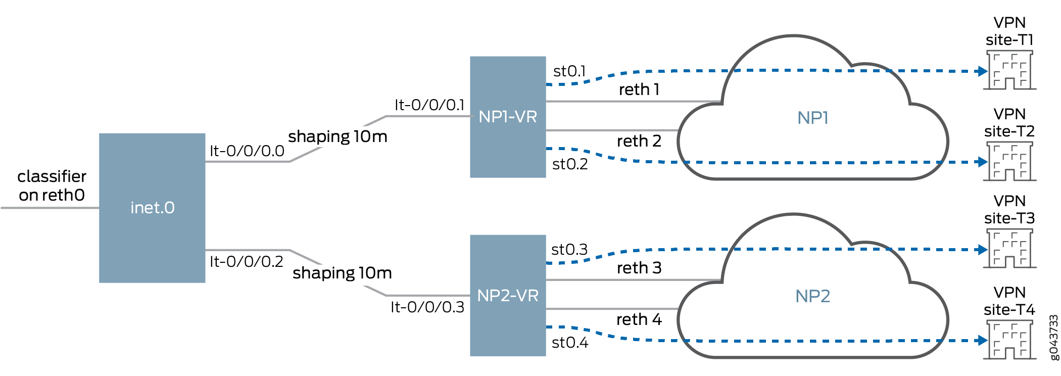
CoS has four typical scenarios that allow connection with remote sites using secure tunnels. However different secure tunnels may connect using different reth interfaces to different Network Providers (NP). For a specific NP, limited uplink bandwidth may be used to prioritize high-priority business and to avoid blindly dropping traffic at the NP side. Currently CoS does not support queuing across physical interfaes (IFD). Having a shared policer does not work as well as queuing, the policer may drop high-priority traffic regardless of priority. To support queuing on an IFD to enable CoS features to prioritize queuing and shaping requires logical tunnel (LT) and NP configuration.
You must define a pair of logical tunnels that are one-to-one mapped to NPs and redirect traffic with routing to the LT interface before encrypting the traffic through a secure tunnel.
For example, configure lt-0/0/0.0 and lt-0/0/0.1 to connect inet 0 and NP1 (virtual router) and configure a static route to redirect traffic to NP1 as lt-0/0/0.0 next-hop. Because NP1 has 10mbps bandwidth for upstream traffic, lt-0/00.0 can be configured with 10mbps of bandwidth shaping. See Figure 1.
routing-instances {
    NP1 {
        instance-type virtual-router;
        interface lt-0/0/0.1;
        interface lo0.0;
        interface reth1.0;
        interface reth2.0;
        interface st0.1;
        interface st0.2;
        routing-options {
            static {
                route 59.200.200.1/32 next-hop <next-hop addr of ipsec tunnel st0.1>;
                route 59.200.200.2/32 next-hop <next-hop addr of ipsec tunnel st0.2>;
                route 60.60.60.1/32 next-hop st0.1;
                route 60.60.60.2/32 next-hop st0.2;
                route 58.58.58.1/32 next-hop lt-0/0/0.1;
                route 58.58.58.2/32 next-hop lt-0/0/0.1;
            }
        }
    }
    NP2 {
        instance-type virtual-router;
        interface lt-0/0/0.3;
        interface lo0.1;
        interface reth3.0;
        interface reth4.0;
        interface st0.3;
        interface st0.4;
        routing-options {
            static {
                route 59.200.200.3/32 next-hop <next-hop addr of ipsec tunnel st0.3>;
                route 59.200.200.4/32 next-hop <next-hop addr of ipsec tunnel st0.4>;
                route 60.60.60.3/32 next-hop st0.3;
                route 60.60.60.4/32 next-hop st0.4;
                route 58.58.58.3/32 next-hop lt-0/0/0.3;
                route 58.58.58.4/32 next-hop lt-0/0/0.3;
            }
        }
    }
}


routing-options {
    static {
        route 60.60.60.1/32 next-hop lt-0/0/0.0;
        route 60.60.60.2/32 next-hop lt-0/0/0.0;
        route 60.60.60.3/32 next-hop lt-0/0/0.2;
        route 60.60.60.4/32 next-hop lt-0/0/0.2;
    }
}

class-of-service {
    interfaces {
        lt-0/0/0 {
            unit 0 {
                shaping-rate 10m;
            }
            unit 2 {
                shaping-rate 10m;
            }
}
How CoS Queuing Works
Figure 2 shows CoS-related processing that occurs for traffic entering and exiting a tunnel. For information on flow-based packet processing, see the Flow-Based and Packet-Based Processing User Guide for Security Devices.
Limitations on CoS Shapers for Tunnel Interfaces
When defining a CoS shaping rate on a tunnel interface, be aware of the following restrictions:
-
The shaping rate on the tunnel interface must be less than that of the physical egress interface.
-
The shaping rate only measures the packet size that includes the Layer 3 packet with GRE or IP-IP encapsulation. The Layer 2 encapsulation added by the physical interface is not factored into the shaping rate measurement.
-
The CoS behavior works as expected only when the physical interface carries the shaped GRE or IP-IP tunnel traffic alone. If the physical interface carries other traffic, thereby lowering the available bandwidth for tunnel interface traffic, the CoS features do not work as expected.
-
You cannot configure a logical interface shaper and a virtual circuit shaper simultaneously on the router. If virtual circuit shaping is desired, do not define a logical interface shaper. Instead, define a shaping rate for all the virtual circuits.