
ON THIS PAGE
Example: Configuring WPS
Use this example to configure Weighted Packet Spray (WPS) in a leaf–spine IP fabric. By selectively spraying traffic across multiple equal‑cost paths based on available bandwidth, WPS enhances link utilization, reduces the risk of packet loss, and maintains stable performance with improved traffic distribution.
|
Readability Score |
|
|
Reading Time |
Less than 15 minutes. |
|
Configuration Time |
Less than an hour. |
Example Prerequisites
|
Hardware requirements |
QFX5240 switches are used to build the toplogy. Always confirm exact platform/release availability in the Release Notes or Feature Explorer |
|
Software requirements |
Junos OS Evolved Release starting 25.2X100-D10 |
Before You Begin
|
Benefits |
|
| Useful Resources: | |
|
Know more |
|
|
Hands-on experience |
|
|
Learn more |
Functional Overview
| Protocols |
|
| Firewall Filters |
|
| Policies |
|
|
Primary verification tasks |
|
Topology Overview
|
Device |
Role |
Function in this example |
|---|---|---|
|
Spine1 and Spine2 |
Spine switches |
Spine devices in typical IP fabric setup. Provide multiple equal cost paths to the leaf devices. |
|
Leaf1 and Leaf2 |
Leaf switches |
Provides baseline ECMP paths to both spines. Performs packet‑level proportional load balancing based on WECMP next-hop weights |
|
H1, H2, H3, H4, H5, H6 |
Host devices |
Initiate traffic flow |
Topology Illustration
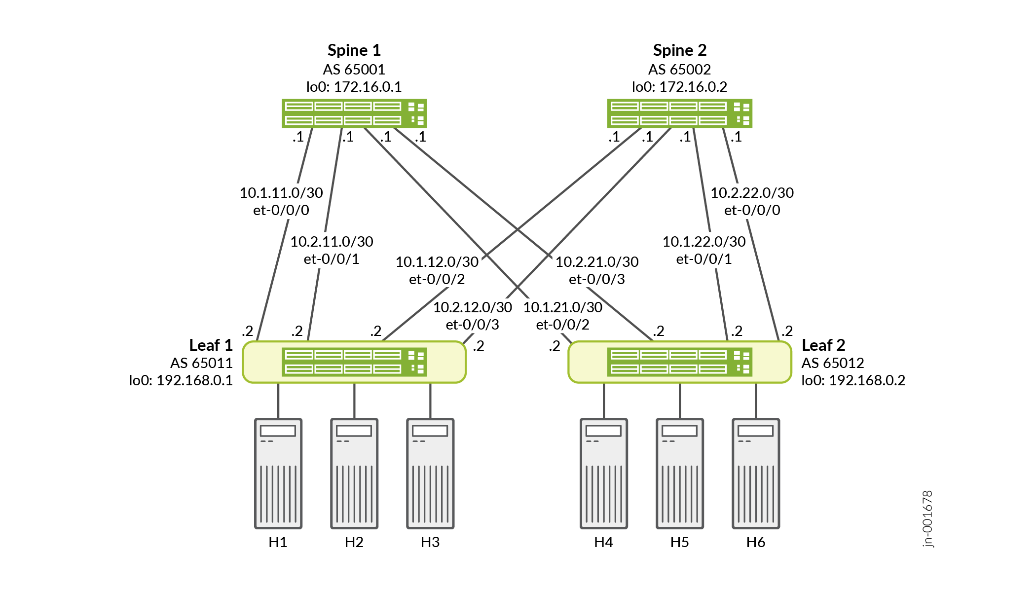
In this topology, two leaf switches (Leaf1 and Leaf2) and two spines (Spine1 and Spine2) form an IP fabric running BGP multipath. Each spine uses the standard BGP link‑bandwidth extended community. When multiple equal‑cost links are present, the spine computes and advertises an aggregated bandwidth value using that same community. Leaf2 applies a firewall filter to enable Weighted Packet Spray (WPS) on selected ingress interfaces, so matching traffic is forwarded proportionally across ECMP next hops based on computed weights, while non‑matching traffic continues to use standard ECMP/WECMP behavior.
The leaf and spine devices are interconnected by two back‑to‑back 100G links per leaf–spine pair (200G total). During steady state, hosts H1–H4, H2–H5, and H3–H6 each send traffic at 90% line rate, totaling 270G. With basic ECMP per‑packet load balancing, each 90G flow is distributed evenly across all four available uplinks, sending approximately 135G toward each spine. Since each spine has 200G of egress capacity (2×100G), both spines can forward this traffic without congestion.
When weighted ECMP is enabled using BGP auto-sensed link bandwidth, each spine detects its uplink capacity toward connected leaves and attaches a link-bandwidth community to routes learned from them. As spines re‑advertise these routes toward Leaf2, they also include an aggregate‑bandwidth community representing the sum of their active uplink capacities. In steady state, Leaf2 receives identical aggregate‑bandwidth values from both spines across all four BGP sessions, resulting in equal WECMP weights.
If one of the two 100G links between Spine2 and Leaf1 fails, Spine2 now has only 100G of available bandwidth toward Leaf1. Spine2 therefore advertises a lower aggregate‑bandwidth value to Leaf2, while Spine1—still operating with two 100G links—advertises a higher aggregate‑bandwidth value. With these updated communities, Leaf2 recomputes weighted ECMP next hops and shifts more traffic toward Spine1 and less toward Spine2 to reflect the new bandwidth ratios. This prevents oversubscription on Spine2’s reduced 100G egress path.
However, under standard ECMP, Leaf2 lacks bandwidth awareness and continues forwarding traffic evenly to both spines. Spine2 still receives 135G but can forward only 100G, creating a 35G oversubscription. This results in egress queue buildup and packet drops on Spine2. These active tail drops can be observed using operational commands on the affected device.
Step-by-Step Configuration on Spine1
For complete sample configurations on the DUT, see:
Configure device identity.
[edit system]
user@Spine1# set  host-name Spine1
Configure device interfaces inlcuding loopback interface.
[edit interfaces]
user@Spine1# set et-0/0/0 description "Connects to Leaf1"
user@Spine1# set et-0/0/0 unit 0 family inet address 10.1.11.1/30
user@Spine1# set et-0/0/1 unit 0 description "Connects to Leaf1"
user@Spine1# set et-0/0/1 unit 0 family inet address 10.2.11.1/30
user@Spine1# set et-0/0/2 description "Connects to Leaf2"
user@Spine1# set et-0/0/2 unit 0 family inet address 10.1.21.1/30
user@Spine1# set et-0/0/3 description "Connects to Leaf2"
user@Spine1# set et-0/0/3 unit 0 family inet address 10.2.21.1/30
Configure the bandwidth aggregation policy, route export policy, and the conditional link bandwidth sensing policies.
[edit policy-options]
user@Spine1# set policy-statement AGGR_BW term 1 then aggregate-bandwidth transitive
user@Spine1# set policy-statement AGGR_BW term 1 then accept
user@Spine1# set policy-statement EXPORT-CONNECTED term 1 from protocol direct
user@Spine1# set policy-statement EXPORT-CONNECTED term 1 then accept
user@Spine1# set policy-statement LBW_CONDITIONAL_AUTOSENSE term HAS_LBWC from community BGP_TRANSITIVE_LBW
user@Spine1# set policy-statement LBW_CONDITIONAL_AUTOSENSE term HAS_LBWC from community BGP_BAND_TRANSITIVE_LBW
user@Spine1# set policy-statement LBW_CONDITIONAL_AUTOSENSE term HAS_LBWC then next policy
user@Spine1# set policy-statement LBW_CONDITIONAL_AUTOSENSE term ADD_LBWC then auto-link-bandwidth transitive
user@Spine1# set policy-statement LBW_CONDITIONAL_AUTOSENSE term ADD_LBWC then next policy
Note: The import and export policies enable link-bandwidth signaling, aggregate on the spines, and propagate bandwidth information used for WECMP and WPS calculations. In production deployments, administrators must control link-bandwidth communities at fabric boundaries. Network engineers should filter or remove these communities at domain edges to prevent propagation beyond the intended routing domain.Configure the per-packet load balancing policy and apply it to the forwarding table.
[edit policy-options]
user@Spine1# set policy-statement PPLB then load-balance per-packet

[edit routing-options]
user@Spine1# set forwarding-table export PPLB
Configure BGP communities that identify routes carrying bandwidth information for intelligent load balancing.
[edit policy-options]
user@Spine1# set community BGP_BAND_TRANSITIVE_LBW members bandwidth-transitive:*:*
user@Spine1# set community BGP_TRANSITIVE_LBW members bandwidth:*:*
Configure autonomus system and router ID for the device.
[edit routing-options]
user@Spine1# set router-id 172.16.0.1
user@Spine1# set autonomous-system 65001
Configure the BGP neighbors and peer group for leaf devices.
[edit protocols]
user@Spine1# set bgp group LEAVES type external
user@Spine1# set bgp group LEAVES description "eBGP to Leaves"
user@Spine1# set bgp group LEAVES import LBW_CONDITIONAL_AUTOSENSE
user@Spine1# set bgp group LEAVES family inet unicast
user@Spine1# set bgp group LEAVES export EXPORT-CONNECTED
user@Spine1# set bgp group LEAVES export AGGR_BW
user@Spine1# set bgp group LEAVES neighbor 192.168.0.1 peer-as 65011
user@Spine1# set bgp group LEAVES neighbor 192.168.0.2 peer-as 65012
Enable eBGP multipath peering toward the leaf devices and enable auto‑sensed link bandwidth.
[edit protocols]
user@Spine1# set bgp group LEAVES link-bandwidth auto-sense
user@Spine1# set bgp multipath multiple-as
Step-by-Step Configuration on Leaf1
Configure device identity.
[edit system]
user@Leaf1# set  host-name Leaf1
Configure device interfaces inlcuding loopback interface.
[edit interfaces]
user@Leaf1# set interfaces et-0/0/0 description "Connects to Spine1"
user@Leaf1# set interfaces et-0/0/0 unit 0 family inet address 10.1.11.2/30
user@Leaf1# set interfaces et-0/0/1 description "Connects to Spine1"
user@Leaf1# set interfaces et-0/0/1 unit 0 family inet address 10.2.11.2/30
user@Leaf1# set interfaces et-0/0/2 description "Connects to Spine2"
user@Leaf1# set interfaces et-0/0/2 unit 0 family inet address 10.1.12.2/30
user@Leaf1# set interfaces et-0/0/3 description "Connects to Spine2"
user@Leaf1# set interfaces et-0/0/3 unit 0 family inet address 10.2.12.2/30
user@Leaf1# set interfaces irb unit 3111 family inet address 101.0.111.1/24
user@Leaf1# set interfaces lo0 unit 0 family inet address 192.168.0.1/32
Configure the IRB interface on Leaf1 to act as the default gateway for hosts (H1–H3) and to originate the test prefix.
user@Leaf1# set interfaces et-0/0/11 description "Connects to Host1"
user@Leaf1# set interfaces et-0/0/11 unit 0 family ethernet-switching vlan members VLAN-HOSTS-3111
user@Leaf1# set interfaces et-0/0/12 description "Connects to Host2"
user@Leaf1# set interfaces et-0/0/12 unit 0 family ethernet-switching vlan members VLAN-HOSTS-3111
user@Leaf1# set interfaces et-0/0/13 description "Connects to Host3"
user@Leaf1# set interfaces et-0/0/13 unit 0 family ethernet-switching vlan members VLAN-HOSTS-3111
user@Leaf1# set protocols router-advertisement interface irb.3111
user@Leaf1# set vlans VLAN-HOSTS-3111 vlan-id 3111
user@Leaf1# set vlans VLAN-HOSTS-3111 l3-interface irb.3111
Configure the route export policy.
[edit policy-options]user@Leaf# set policy-options policy-statement EXPORT-CONNECTED term 1 from protocol direct
user@Leaf1# set policy-options policy-statement EXPORT-CONNECTED term 1 then accept
user@Leaf1# set policy-statement EXPORT-CONNECTED term 1 then accept
Configure the per-packet load balancing policy and apply it to the forwarding table.
[edit policy-options]
user@Leaf1# set policy-options policy-statement PPLB then load-balance per-packet
Configure BGP communities that identify routes carrying bandwidth information for intelligent load balancing.
[edit policy-options]
user@Leaf1# set community BGP_BAND_TRANSITIVE_LBW members bandwidth-transitive:*:*
user@Leaf1# set community BGP_TRANSITIVE_LBW members bandwidth:*:*
Configure autonomus system and router ID for the device.
[edit routing-options]
user@Leaf1# set router-id 192.168.0.1
user@Leaf1# set autonomous-system 65011
user@Leaf1# set forwarding-table export PPLB
Configure the BGP neighbors and peer group for leaf devices.
[edit protocols]user@Leaf1# bgp group SPINES type external
user@Leaf1# bgp group SPINES description "eBGP to Spines"
user@Leaf1# bgp group SPINES family inet unicast
user@Leaf1# bgp group SPINES export EXPORT-CONNECTED
user@Leaf1# bgp group SPINES neighbor 172.16.0.1 peer-as 65001
user@Leaf1# bgp group SPINES neighbor 172.16.0.2 peer-as 65002
Enable eBGP multipath peering toward the leaf devices and enable auto‑sensed link bandwidth.
[edit protocols]
user@Leaf1# set bgp group LEAVES bfd-liveness-detection minimum-interval 1000
user@Leaf1# set bgp group LEAVES bfd-liveness-detection multiplier 3
user@Leaf1# set bgp group LEAVES link-bandwidth auto-sense
user@Leaf1# set bgp multipath multiple-as
Step-by-Step Configuration on Leaf2
For complete sample configurations on the DUT, see:
Configure device identity.
[edit system]
user@Leaf2# set  host-name Leaf2
Configure device interfaces inlcuding loopback interface and enable weighted packet spray.
[edit interfaces]
user@Leaf2# set et-0/0/2 description "Connects to Spine1"
user@Leaf2# set et-0/0/2 unit 0 family inet address 10.1.21.2/30
user@Leaf2# set et-0/0/3 description "Connects to Spine1"
user@Leaf2# set et-0/0/3 unit 0 family inet address 10.2.21.2/30
user@Leaf2# set et-0/0/1 description "Connects to Spine2"
user@Leaf2# set et-0/0/1 unit 0 family inet address 10.1.22.2/30
user@Leaf2# set et-0/0/0 description "Connects to Spine2"
user@Leaf2# set et-0/0/0 unit 0 family inet address 10.2.22.2/30
user@Leaf2# set interfaces irb unit 3222 family inet address 101.0.122.1/24
user@Leaf2# set lo0 unit 0 family inet address 192.168.0.2/32
Configure an optional IRB interface on Leaf2 to act as the default gateway for hosts (H4–H6).
user@Leaf2# set interfaces et-0/0/14 description "Connects to Host4"
user@Leaf2# set interfaces et-0/0/14 unit 0 family ethernet-switching vlan members VLAN-HOSTS-3222
user@Leaf2# set interfaces et-0/0/15 description "Connects to Host5"
user@Leaf2# set interfaces et-0/0/15 unit 0 family ethernet-switching vlan members VLAN-HOSTS-3222
user@Leaf2# set interfaces et-0/0/16 description "Connects to Host6"
user@Leaf2# set interfaces et-0/0/16 unit 0 family ethernet-switching vlan members VLAN-HOSTS-3222
user@Leaf2# set vlans VLAN-HOSTS-3222 vlan-id 3222
user@Leaf2# set vlans VLAN-HOSTS-3222 l3-interface irb.3222
Configure the bandwidth aggregation policy, route export policy, and the conditional link bandwidth sensing policies.
[edit policy-options]
user@Leaf2# set policy-statement EXPORT-CONNECTED term 1 from protocol direct
user@Leaf2# set policy-statement EXPORT-CONNECTED term 1 then accept
Configure the per-packe load balancing policy and apply it to the forwarding table.
[edit policy-options]
user@Leaf2# set policy-statement PPLB then load-balance per-packet

[edit routing-options]
user@Leaf2# set forwarding-table export PPLB
Configure BGP communities that identify routes carrying bandwidth information for intelligent load balancing.
[edit policy-options]
user@Leaf2# set community BGP_BAND_TRANSITIVE_LBW members bandwidth-transitive:*:*
user@Leaf2# set community BGP_TRANSITIVE_LBW members bandwidth:*:*
Configure Firewall Filter for Weighted Packet Spray.
[edit firewall]

user@Leaf2# set family inet filter WEIGHTED_PKT_SPRAY_v4 term packet_spray from protocol udp
user@Leaf2# set family inet filter WEIGHTED_PKT_SPRAY_v4 term packet_spray from source-port 50001
user@Leaf2# set family inet filter WEIGHTED_PKT_SPRAY_v4 term packet_spray then weighted-packet-spray
user@Leaf2# set family inet filter WEIGHTED_PKT_SPRAY_v4 term default then accept
Note: WPS might reorder packets and should only apply to flows that can tolerate such reordering. The firewall filter serves as the control point for selectively enabling packet spray, while it forwards other traffic normally.Add the Firewall Filter to an interface.
user@Leaf2# set interfaces irb unit 3222 family inet filter input WEIGHTED_PKT_SPRAY_v4
Configure autonomus system and router ID for the device.
[edit routing-options]
user@Leaf2# set router-id 192.168.0.2
user@Leaf2# set autonomous-system 65012
Configure the BGP neighbors and peer group for spine devices.
[edit protocols]
user@Leaf2# set bgp group SPINES type external
user@Leaf2# set bgp group SPINES description "eBGP to Spines"
user@Leaf2# set bgp group SPINES family inet unicast
user@Leaf2# set bgp group SPINES export EXPORT-CONNECTED
user@Leaf2# set bgp group SPINES neighbor 172.16.0.1 peer-as 65001
user@Leaf2# set bgp group SPINES neighbor 172.16.0.2 peer-as 65002
Enable eBGP multipath peering toward the spine devices and enable auto‑sensed link bandwidth.
[edit protocols]
user@Leaf2# set bgp group SPINES bfd-liveness-detection minimum-interval 1000
user@Leaf2# set bgp group SPINES bfd-liveness-detection multiplier 3
user@Leaf2# set bgp group SPINES link-bandwidth auto-sense
user@Leaf2# set bgp multipath multiple-as
Verification
- Verify the IRB interface and connected prefix on Leaf1
- Verify the connected route in the RIB on Leaf1
- Verify how Spine1 learns the prefix from Leaf1 through eBGP peering
- Verify that Spine1 installs the prefix with Link-Bandwidth communities (auto-sense + import policy)
- Verify that Spine1 advertises the prefix with aggregate bandwidth toward Leaf2
- Verify that Spine1 installs the prefix with imported link‑bandwidth communities
- Verify on Leaf2 that the prefix arrives from both spines with bandwidth communities and 4-way ECMP
- Test Action: Initiate Link Failure
- Verify Post-Failure WECMP and WPS Behavior on Leaf2
- Cross-check Spine2 also advertises the prefix with aggregate bandwidth downstream
- Verify WECMP + WPS steady state on Leaf2
Verify the IRB interface and connected prefix on Leaf1
Purpose
Confirm that you have configured the local subnet on the access IRB and verified its operational status, allowing the device to originate and export the local route into BGP.
Action
user@Leaf1 >show interfaces terse irb.3111Interface Admin Link Proto Local Remote irb.3111 up up inet 101.0.111.1/24 fe80::4236:b70c:27d4:aa37/64 multiservice user@Leaf1>show route protocol direct match-prefix 101.0.111.0inet.0: 12108 destinations, 30155 routes (12107 active, 0 holddown, 1 hidden) + = Active Route, - = Last Active, * = Both 101.0.111.0/24 *[Direct/0] 2d 23:26:08 > via irb.3111 inet6.0: 12154 destinations, 30197 routes (12154 active, 0 holddown, 0 hidden)
Meaning
irb.3111 is up/up and IPv4 shows 101.0.111.1/24. These confirm that the connected network exists and is installed in the RIB.
Verify the connected route in the RIB on Leaf1
Purpose
Ensure the local IRB-connected network is installed as a Direct route (the source for further BGP advertisement).
Action
user@Leaf1> show route protocol direct match-prefix 101.0.111.0
inet.0: 12108 destinations, 30155 routes (12107 active, 0 holddown, 1 hidden)
+ = Active Route, - = Last Active, * = Both
101.0.111.0/24     *[Direct/0] 2d 23:26:08
                    >  via irb.3111
inet6.0: 12154 destinations, 30197 routes (12154 active, 0 holddown, 0 hidden)
Meaning
101.0.111.0/24 appears as *[Direct/0] via irb.3111 - Confirms the origin of the route before it is exported into BGP.
Verify how Spine1 learns the prefix from Leaf1 through eBGP peering
Purpose
Confirm BGP multipath on the spine: the prefix is learned over both back‑to‑back leaf links, each accepted as part of ECMP.
Action
user@Spine1>show route receive-protocol bgp 10.1.11.2 match-prefix 101.0.111.0 extensiveWarning: License key missing; requires 'bgp' license inet.0: 12066 destinations, 24102 routes (12065 active, 0 holddown, 1 hidden) * 101.0.111.0/24 (2 entries, 1 announced) Accepted Multipath Nexthop: 10.1.11.2 AS path: 65011 I user@Spine1>show route receive-protocol bgp 10.2.11.2 match-prefix 101.0.111.0 extensiveWarning: License key missing; requires 'bgp' license inet.0: 12066 destinations, 24102 routes (12065 active, 0 holddown, 1 hidden) 101.0.111.0/24 (2 entries, 1 announced) Accepted MultipathContrib Nexthop: 10.2.11.2 AS path: 65011 I inet6.0: 12071 destinations, 24103 routes (12071 active, 0 holddown, 0 hidden)
Meaning
First neighbor shows Accepted Multipath; second shows Accepted MultipathContrib - Confirms two ECMP contributors for the same destination from Leaf1 to Spine1.
Verify that Spine1 installs the prefix with Link-Bandwidth communities (auto-sense + import policy)
Purpose
Ensure the spine attaches bandwidth community to the received leaf prefix (even if the leaf didn’t send one) by using auto-link bandwidth on import.
Action
user@Spine1> show route 101.0.111.0/24 extensive | no-more

inet.0: 12066 destinations, 24102 routes (12065 active, 0 holddown, 1 hidden)
101.0.111.0/24 (2 entries, 1 announced)
TSI:
KRT in-kernel 101.0.111.0/24 -> {list:10.1.11.2, 10.2.11.2}
Multipath TSI
    Flags: RTargetLBWSet
    Lead Route: BGP, 10.1.11.2
    Nexthop:
      Refcnt: 6015
      Template: 0x562fb6413c10(Router, 2 legs)
      Object: 0x562fb481089c(Router, 2 legs)
    Mode: Multipath
Page 0 idx 1, (group LEAVES type External) Type 1 val 0x562fb72eb8d0 (adv_entry)
   Advertised metrics:
     Nexthop: Self
     AS path: [65001] 65011 I
     Communities: bandwidth:65001:99999997952
    Advertise: 0000000c
Path 101.0.111.0
from 10.1.11.2
Vector len 4.  Val: 1
        *BGP    Preference: 170/-101
                Next hop type: Router, Next hop index: 0
                Address: 0x562fb481089c
                Next-hop reference count: 6016, Next-hop session id: 0
                Kernel Table Id: 0
                Source: 10.1.11.2
                Next hop: 10.1.11.2 via et-0/0/2 balance 50%
                Next hop: 10.2.11.2 via et-0/0/3 balance 50%, selected
                State: <Active Ext>
                Local AS: 65001 Peer AS: 65011
                Age: 6:48:11
                Announcement bits (3): 0-KRT 2-BGP_Multi_Path 3-BGP_RT_Background
                AS path: 65011 I
                Communities: bandwidth:65001:49999998976
                Accepted Multipath
                Localpref: 100
                Router ID: 10.0.0.101
         BGP    Preference: 170/-101
                Next hop type: Router, Next hop index: 8375
                Address: 0x562fbbcadb3c
                Next-hop reference count: 6019, Next-hop session id: 93
                Kernel Table Id: 0
                Source: 10.2.11.2
                Next hop: 10.2.11.2 via et-0/0/3, balance 50%
                Accepted MultipathContrib
                AS path: 65011 I
                Communities: bandwidth:65001:49999998976
Meaning
Look for flags like RTargetLBWSet and Communities: bandwidth:<asn>:<bps>. You should see two ECMP next hops (50/50) to Leaf1 and a bandwidth community per path (e.g., bandwidth:23456:49999998976). This proves the spine derived and attached LBW values through import policy.
Verify that Spine1 advertises the prefix with aggregate bandwidth toward Leaf2
Verify that Spine1 installs the prefix with imported link‑bandwidth communities
Purpose
Verify that Spine1 imports per‑link bandwidth information from Leaf1 before computing an aggregate bandwidth value.
Action
user@Spine1> show route 101.0.111.0/24 extensive | match bandwidth
                         Communities: bandwidth:65001:49999998976
                         Communities: bandwidth:65001:49999998976
Meaning
Each BGP path learned from Leaf1 carries a link‑bandwidth extended community representing the auto‑sensed bandwidth of that individual uplink. Spine1 uses these values to compute an aggregated bandwidth for downstream advertisement.
Purpose
Confirm the aggregate-bandwidth community is added on export so downstream devices learn total available capacity.
Action
user@Spine1> show route advertising-protocol bgp 10.2.21.2 match-prefix 101.0.111.0/24 extensive
Warning: License key missing; requires 'bgp' license

inet.0: 12066 destinations, 24102 routes (12065 active, 0 holddown, 1 hidden)
* 101.0.111.0/24 (2 entries, 1 announced)
 BGP group LEAVES type External
     Nexthop: Self
     AS path: 65011 I
     Communities: bandwidth:65001:99999997952
Meaning
Look for Communities: bandwidth:...:99999997952 (example value = aggregate of equal links). Confirms aggregate bandwidth is propagated to leaves through BGP out of the spine.
Verify on Leaf2 that the prefix arrives from both spines with bandwidth communities and 4-way ECMP
Purpose
Ensure the leaf receives the prefix from both spines (two paths per spine) and installs four multipath next hops with the same LBW community, enabling WECMP/WPS.
Action
user@Leaf2> show route 101.0.111.0/24 extensive | no-more
inet.0: 12100 destinations, 30165 routes (12099 active, 0 holddown, 1 hidden)
101.0.111.0/24 (4 entries, 1 announced)
TSI:
KRT in-kernel 101.0.111.0/24 -> {list:10.1.21.1, 10.2.21.1, 10.1.22.1, 10.2.22.1}
Multipath TSI
    Flags: RTargetLBWSet
    Lead Route: BGP, 10.1.21.1
    Nexthop:
      Refcnt: 6013
      Template: 0x55cbb0413c10(Router, 4 legs)
      Object: 0x55cbb49678dc(Router, 4 legs)
    Mode: Multipath
Page 0 idx 1, (group IXIA-iBGP type Internal) Type 1 val 0x55cbb6e63068 (adv_entry)
   Advertised metrics:
     Nexthop: 10.1.21.1
     Localpref: 100
     AS path: 65001 65011 I
     Communities:
    Advertise: 00000001
Path 101.0.111.0
from 10.2.21.1
Vector len 4.  Val: 1
        *BGP    Preference: 170/-101
                Next hop type: Router, Next hop index: 0
                Address: 0x55cbb49678dc
                Next-hop reference count: 6014, Next-hop session id: 0
                Kernel Table Id: 0
                Source: 10.1.21.1
                Next hop: 10.1.21.1 via et-0/0/2 balance 25%
                Session Id: 0
                Next hop: 10.2.21.1 via et-0/0/3 balance 25%
                Session Id: 0
                Next hop: 10.1.22.1 via et-0/0/1 balance 25%, selected
                Session Id: 0
                Next hop: 10.2.22.1 via et-0/0/0 balance 25%
                Session Id: 0
                State: <Active Ext>
                Local AS: 65012 Peer AS: 65001
                Age: 7:00:33
                Validation State: unverified
                Task: BGP_65001.10.1.21.1
                Announcement bits (4): 0-KRT 2-BGP_Multi_Path 3-BGP_RT_Background 4-Resolve tree 3
                AS path: 65001 65011 I
                Communities: bandwidth:65001:99999997952
                Accepted Multipath
                Localpref: 100
                Router ID: 192.168.0.2
                Thread: junos-main
         BGP    Preference: 170/-101
                Next hop type: Router, Next hop index: 9975
                Address: 0x55cbc31634fc
                Next-hop reference count: 6023, Next-hop session id: 54
                Kernel Table Id: 0
                Source: 10.2.21.1
                Next hop: 10.2.21.1 via et-0/0/3, selected
                Session Id: 54
                State: <NotBest Ext>
                Inactive reason: Not Best in its group - Update source
                Local AS: 65012 Peer AS: 65001
                Age: 7:08:32
                Validation State: unverified
                Task: BGP_65001.10.2.21.1
                AS path: 65001 65011 I
                Communities: bandwidth:65001:99999997952
                Accepted MultipathContrib
                Localpref: 100
                Router ID: 192.168.0.2
                Thread: junos-main
         BGP    Preference: 170/-101
                Next hop type: Router, Next hop index: 9144
                Address: 0x55cbb5ca087c
                Next-hop reference count: 6020, Next-hop session id: 67
                Kernel Table Id: 0
                Source: 10.1.22.1
                Next hop: 10.1.22.1 via et-0/0/1, selected
                Session Id: 67
                State: <NotBest Ext>
                Inactive reason: Not Best in its group - Active preferred
                Local AS: 65012 Peer AS: 65001
                Age: 7:00:37
                Validation State: unverified
                Task: BGP_65002.10.1.22.1
                AS path: 65001 65011 I
                Communities: bandwidth:65002:99999997952
                Accepted MultipathContrib
                Localpref: 100
                Router ID: 192.168.0.2
                Thread: junos-main
         BGP    Preference: 170/-101
                Next hop type: Router, Next hop index: 9146
                Address: 0x55cbb725d57c
                Next-hop reference count: 6023, Next-hop session id: 68
                Kernel Table Id: 0
                Source: 10.2.22.1
                Next hop: 10.2.22.1 via et-0/0/0, selected
                Session Id: 68
                State: <NotBest Ext>
                Inactive reason: Not Best in its group - Active preferred
                Local AS: 65012 Peer AS: 65001
                Age: 7:00:33
                Validation State: unverified
                Task: BGP_65002.10.2.22.1
                AS path: 65001 65011 I
                Communities: bandwidth:65002:99999997952
                Accepted MultipathContrib
                Localpref: 100
                Router ID: 192.168.0.2
                Thread: junos-main
Meaning
Look for the four next hops (two via Spine1 and two via Spine2). Balances at steady state should be 25% each. Communities: bandwidth:…:99999997952 present on all paths.
Test Action: Initiate Link Failure
Purpose
Simulate lower fabric bandwidth by disabling one uplink between Spine2 and Leaf1.
Action
user@Spine2# set interfaces et-0/0/0 disableVerify Post-Failure WECMP and WPS Behavior on Leaf2
Purpose
Confirm that Leaf2 recalculates WECMP weights and updates WPS forwarding behavior after the link failure.
Action
user@Leaf2>show route 101.0.111.0/24 detail | match bandwidthCommunities: bandwidth:65001:99999997952 Communities: bandwidth:65001:12499999744 Communities: bandwidth:65002:12499999744 Communities: bandwidth:65002:99999997952 user@Leaf2>show route 101.0.111.0/24 detail | match balanceNext hop: 10.1.21.1 via et-0/0/2 balance 17% Next hop: 10.2.21.1 via et-0/0/3 balance 33% Next hop: 10.1.22.1 via et-0/0/1 balance 33% Next hop: 10.2.22.1 via et-0/0/0 balance 17%, selected
Meaning
This confirms dynamic WECMP recalculation and correct WPS proportional packet spraying following a link failure.
Cross-check Spine2 also advertises the prefix with aggregate bandwidth downstream
Purpose
Validate consistency across spines—both must export the same bandwidth community semantics, enabling coherent WECMP at the leaves.
Action
user@Spine2>show route 101.0.111.0/24 extensive | no-moreinet.0: 12063 destinations, 24099 routes (12062 active, 0 holddown, 1 hidden) 101.0.111.0/24 (2 entries, 1 announced) TSI: KRT in-kernel 101.0.111.0/24 -> {list:10.1.12.2, 10.2.12.2} Multipath TSI Flags: RTargetLBWSet Lead Route: BGP, 10.1.12.2 Nexthop: Refcnt: 6015 Template: 0x56187d412110(Router, 2 legs) Object: 0x56187c01101c(Router, 2 legs) Mode: Multipath Page 0 idx 0, (group LEAVES type External) Type 1 val 0x5618873ad838 (adv_entry) Advertised metrics: Nexthop: Self AS path: [65002] 65011 I Communities: bandwidth:65002:99999997952 Advertise: 0000000c Path 101.0.111.0 from 10.1.12.2 Vector len 4. Val: 0 *BGP Preference: 170/-101 Next hop type: Router, Next hop index: 0 Address: 0x56187c01101c Next-hop reference count: 6016, Next-hop session id: 0 Kernel Table Id: 0 Source: 10.1.12.2 Next hop: 10.1.12.2 via et-0/0/2 balance 50% Session Id: 0 Next hop: 10.2.12.2 via et-0/0/3 balance 50%, selected Session Id: 0 State: <Active Ext> Local AS: 65002 Peer AS: 65011 Age: 7:24:59 Validation State: unverified Task: BGP_65011.10.1.12.2 Announcement bits (3): 0-KRT 2-BGP_Multi_Path 3-BGP_RT_Background AS path: 65011 I Communities: bandwidth:65002:49999998976 Accepted Multipath Localpref: 100 Router ID: 172.16.0.2 Thread: junos-main BGP Preference: 170/-101 Next hop type: Router, Next hop index: 9264 Address: 0x5618852b4bdc Next-hop reference count: 6019, Next-hop session id: 38 Kernel Table Id: 0 Source: 10.2.12.2 Next hop: 10.2.12.2 via et-0/0/3, selected Session Id: 38 State: <NotBest Ext> Inactive reason: Not Best in its group - Update source Local AS: 65002 Peer AS: 65011 Age: 7:27:46 Validation State: unverified Task: BGP_65011.10.2.12.2 AS path: 65011 I Communities: bandwidth:65002:49999998976 Accepted MultipathContrib Localpref: 100 Router ID: 172.16.0.2 Thread: junos-main user@Spine2>show route advertising-protocol bgp 10.1.22.2 match-prefix 101.0.111.0/24 extensiveWarning: License key missing; requires 'bgp' license inet.0: 12063 destinations, 24099 routes (12062 active, 0 holddown, 1 hidden) * 101.0.111.0/24 (2 entries, 1 announced) BGP group LEAVES type External Nexthop: Self AS path: 65011 I Communities: bandwidth:65002:99999997952 user@Spine2>show route 101.0.111.0/24 extensive | no-moreinet.0: 12063 destinations, 24099 routes (12062 active, 0 holddown, 1 hidden) 101.0.111.0/24 (2 entries, 1 announced) TSI: KRT in-kernel 101.0.111.0/24 -> {list:10.1.12.2, 10.2.12.2} Multipath TSI Flags: RTargetLBWSet Lead Route: BGP, 10.1.12.2 Nexthop: Refcnt: 6015 Template: 0x56187d412110(Router, 2 legs) Object: 0x56187c01101c(Router, 2 legs) Mode: Multipath Page 0 idx 0, (group LEAVES type External) Type 1 val 0x5618873ad838 (adv_entry) Advertised metrics: Nexthop: Self AS path: [65002] 65011 I Communities: bandwidth:65002:99999997952 Advertise: 0000000c Path 101.0.111.0 from 10.1.12.2 Vector len 4. Val: 0 *BGP Preference: 170/-101 Next hop type: Router, Next hop index: 0 Address: 0x56187c01101c Next-hop reference count: 6016, Next-hop session id: 0 Kernel Table Id: 0 Source: 10.1.12.2 Next hop: 10.1.12.2 via et-0/0/2 balance 50% Session Id: 0 Next hop: 10.2.12.2 via et-0/0/3 balance 50%, selected Session Id: 0 State: <Active Ext> Local AS: 65002 Peer AS: 65011 Age: 7:24:59 Validation State: unverified Task: BGP_65011.10.1.12.2 Announcement bits (3): 0-KRT 2-BGP_Multi_Path 3-BGP_RT_Background AS path: 65011 I Communities: bandwidth:65002:49999998976 Accepted Multipath Localpref: 100 Router ID: 172.16.0.2 Thread: junos-main BGP Preference: 170/-101 Next hop type: Router, Next hop index: 9264 Address: 0x5618852b4bdc Next-hop reference count: 6019, Next-hop session id: 38 Kernel Table Id: 0 Source: 10.2.12.2 Next hop: 10.2.12.2 via et-0/0/3, selected Session Id: 38 State: <NotBest Ext> Inactive reason: Not Best in its group - Update source Local AS: 65002 Peer AS: 65011 Age: 7:27:46 Validation State: unverified Task: BGP_65011.10.2.12.2 AS path: 65011 I Communities: bandwidth:65002:49999998976 Accepted MultipathContrib Localpref: 100 Router ID: 172.16.0.2 Thread: junos-main
Meaning
Multipath present with the two Leaf1-facing links (50/50). Export shows aggregate bandwidth community matching Spine1's behavior.
Verify WECMP + WPS steady state on Leaf2
Purpose
Confirm that with all links up, weights are equal, bandwidth communities are present for all next hops, and the forwarding table uses a unilist structure ready for packet spray.
Action
user@Leaf2>show route 101.0.111.0/24 extensive | match bandwidthCommunities: bandwidth:65001:99999997952 Communities: bandwidth:65001:99999997952 Communities: bandwidth:65002:99999997952 Communities: bandwidth:65002:99999997952 user@Leaf2 >show route 101.0.111.0/24 extensive | match balanceNext hop: 10.1.21.1 via et-0/0/2 balance 25% Next hop: 10.2.21.1 via et-0/0/3 balance 25% Next hop: 10.1.22.1 via et-0/0/1 balance 25%, selected Next hop: 10.2.22.1 via et-0/0/0 balance 25% user@Leaf2>show route forwarding-table destination 101.0.111.0/24 extensive | match weightNext-hop interface: et-0/0/2:0.0 Weight: 0x0 Balance: 16384 Next-hop interface: et-0/0/3:1.0 Weight: 0x0 Balance: 32768 Next-hop interface: et-0/0/1:0.0 Weight: 0x0 Balance: 49152 Next-hop interface: et-0/0/0:0.0 Weight: 0x0 Balance: 65535 user@Leaf2 >show route forwarding-table destination 101.0.111.0/24 extensive | no-moreRouting table: default.inet [Index: 0] Internet: Destination: 101.0.111.0/24 Route type: user Route reference: 0 Route interface-index: 0 Multicast RPF nh index: 0 P2mpidx: 0 Flags: rt nh decoupled Next-hop type: unilist Index: 9148 Reference: 1 Next-hop type: software Index: 9144 Reference: 1 Next-hop interface: et-0/0/0:0.0 Weight: 0x0 Balance: 16384 Index: 5003 Reference: 1 Nexthop: 10.2.22.1 Next-hop type: unicast Next-hop interface: et-0/0/0:0.0 Next-hop type: software Index: 9146 Reference: 1 Next-hop interface: et-0/0/0:1.0 Weight: 0x0 Balance: 32768 Index: 5996 Reference: 1 Nexthop: 10.1.22.1 Next-hop type: unicast Next-hop interface: et-0/0/0:1.0 Next-hop type: software Index: 9970 Reference: 1 Next-hop interface: et-0/0/3:0.0 Weight: 0x0 Balance: 49152 Index: 5210 Reference: 1 Nexthop: 10.2.21.1 Next-hop type: unicast Next-hop interface: et-0/0/3:0.0 Next-hop type: software Index: 9975 Reference: 1 Next-hop interface: et-0/0/3:1.0 Weight: 0x0 Balance: 65535 Index: 5208 Reference: 1 Nexthop: 10.1.21.1 Next-hop type: unicast Next-hop interface: et-0/0/3:1.0 Routing table: __juniper_private1__.inet [Index: 1] Internet: Routing table: __master.anon__.inet [Index: 51] Internet: Destination: default Route type: permanent Route reference: 0 Route interface-index: 0 Multicast RPF nh index: 0 P2mpidx: 0 Flags: none Next-hop type: reject Index: 9003 Reference: 1 Routing table: mgmt_junos.inet [Index: 36738] Internet: Destination: default Route type: permanent Route reference: 0 Route interface-index: 0 Multicast RPF nh index: 0 P2mpidx: 0 Flags: none Next-hop type: reject Index: 616 Reference: 1
Meaning
You should see four bandwidth communities, one per next hop. Balance 25% on each next hop. FIB shows unilist with evenly stepped balance buckets (e.g., 16384/32768/49152/65535), which the PFE will use for per‑packet weighted spray when the firewall term matches.
Appendix 1: Set Commands on All Devices
Spine1
set system host-name Spine1
set interfaces et-0/0/0 speed 400g
set interfaces et-0/0/0 description "Connects to Leaf1"
set interfaces et-0/0/0 unit 0 family inet address 10.1.11.1/30
set interfaces et-0/0/1 speed 400g
set interfaces et-0/0/1 description "Connects to Leaf2"
set interfaces et-0/0/1 unit 0 family inet address 10.2.11.1/30
set interfaces et-0/0/2 speed 400g
set interfaces et-0/0/2 unit 0 description "Connects to Leaf1"
set interfaces et-0/0/2 unit 0 family inet address 10.1.21.1/30
set interfaces et-0/0/3 speed 400g
set interfaces et-0/0/3 description "Connects to Leaf2"
set interfaces et-0/0/3 unit 0 family inet address 10.2.21.1/30
set interfaces lo0 unit 0 family inet address 172.16.0.1/32
set policy-options policy-statement AGGR_BW term 1 then aggregate-bandwidth transitive
set policy-options policy-statement AGGR_BW term 1 then accept
set policy-options policy-statement EXPORT-CONNECTED term 1 from protocol direct
set policy-options policy-statement EXPORT-CONNECTED term 1 then accept
set policy-options policy-statement LBW_CONDITIONAL_AUTOSENSE term HAS_LBWC from community BGP_TRANSITIVE_LBW
set policy-options policy-statement LBW_CONDITIONAL_AUTOSENSE term HAS_LBWC from community BGP_BAND_TRANSITIVE_LBW
set policy-options policy-statement LBW_CONDITIONAL_AUTOSENSE term HAS_LBWC then next policy
set policy-options policy-statement LBW_CONDITIONAL_AUTOSENSE term ADD_LBWC then auto-link-bandwidth transitive
set policy-options policy-statement LBW_CONDITIONAL_AUTOSENSE term ADD_LBWC then next policy
set policy-options policy-statement PPLB then load-balance per-packet
set policy-options community BGP_BAND_TRANSITIVE_LBW members bandwidth-transitive:*:*
set policy-options community BGP_TRANSITIVE_LBW members bandwidth:*:*
set firewall family inet filter WEIGHTED_PKT_SPRAY term rdma from protocol udp
set firewall family inet filter WEIGHTED_PKT_SPRAY term rdma then accept
set firewall family inet filter WEIGHTED_PKT_SPRAY term rest then accept
set routing-options router-id 172.16.0.1
set routing-options autonomous-system 65001
set routing-options forwarding-table export PPLB
set protocols bgp group LEAVES type external
set protocols bgp group LEAVES description "eBGP to Leaves"
set protocols bgp group LEAVES import LBW_CONDITIONAL_AUTOSENSE
set protocols bgp group LEAVES family inet unicast
set protocols bgp group LEAVES export EXPORT-CONNECTED
set protocols bgp group LEAVES export AGGR_BW
set protocols bgp group LEAVES neighbor 192.168.0.1 peer-as 65011
set protocols bgp group LEAVES neighbor 192.168.0.2 peer-as 65012
set protocols bgp group LEAVES bfd-liveness-detection minimum-interval 1000
set protocols bgp group LEAVES bfd-liveness-detection multiplier 3
set protocols bgp group LEAVES link-bandwidth auto-sense
set protocols bgp multipath multiple-as
set protocols l2-learning global-mac-table-aging-time 3000
Spine2
set system host-name Spine2
set interfaces et-0/0/2 speed 400g
set interfaces et-0/0/2 description "Connects to Leaf1"
set interfaces et-0/0/2 unit 0 family inet address 10.1.12.1/30
set interfaces et-0/0/3 speed 400g
set interfaces et-0/0/3 description "Connects to Leaf2"
set interfaces et-0/0/3 unit 0 family inet address 10.2.12.1/30
set interfaces et-0/0/1 speed 400g
set interfaces et-0/0/1 description "Connects to Leaf1"
set interfaces et-0/0/1 unit 0 family inet address 10.1.22.1/30
set interfaces et-0/0/0 speed 400g
set interfaces et-0/0/0 description "Connects to Leaf2"
set interfaces et-0/0/0 unit 0 family inet address 10.2.22.1/30
set interfaces lo0 unit 0 family inet address 172.16.0.2/32
set policy-options policy-statement AGGR_BW term 1 then aggregate-bandwidth transitive
set policy-options policy-statement AGGR_BW term 1 then accept
set policy-options policy-statement EXPORT-CONNECTED term 1 from protocol direct
set policy-options policy-statement EXPORT-CONNECTED term 1 then accept
set policy-options policy-statement LBW_CONDITIONAL_AUTOSENSE term HAS_LBWC from community BGP_TRANSITIVE_LBW
set policy-options policy-statement LBW_CONDITIONAL_AUTOSENSE term HAS_LBWC from community BGP_BAND_TRANSITIVE_LBW
set policy-options policy-statement LBW_CONDITIONAL_AUTOSENSE term HAS_LBWC then next policy
set policy-options policy-statement LBW_CONDITIONAL_AUTOSENSE term ADD_LBWC then auto-link-bandwidth transitive
set policy-options policy-statement LBW_CONDITIONAL_AUTOSENSE term ADD_LBWC then next policy
set policy-options policy-statement PPLB then load-balance per-packet
set policy-options community BGP_BAND_TRANSITIVE_LBW members bandwidth-transitive:*:*
set policy-options community BGP_TRANSITIVE_LBW members bandwidth:*:*
set firewall family inet filter WEIGHTED_PKT_SPRAY term rdma from protocol udp
set firewall family inet filter WEIGHTED_PKT_SPRAY term rdma then accept
set firewall family inet filter WEIGHTED_PKT_SPRAY term rest then accept
set routing-options router-id 172.16.0.2
set routing-options autonomous-system 65002
set routing-options forwarding-table export PPLB
set protocols bgp group LEAVES type external
set protocols bgp group LEAVES description "eBGP to Spines"
set protocols bgp group LEAVES import LBW_CONDITIONAL_AUTOSENSE
set protocols bgp group LEAVES family inet unicast
set protocols bgp group LEAVES export EXPORT-CONNECTED
set protocols bgp group LEAVES export AGGR_BW
set protocols bgp group LEAVES neighbor 192.168.0.1 peer-as 65011
set protocols bgp group LEAVES neighbor 192.168.0.2 peer-as 65012
set protocols bgp group LEAVES bfd-liveness-detection minimum-interval 1000
set protocols bgp group LEAVES bfd-liveness-detection multiplier 3
set protocols bgp group LEAVES link-bandwidth auto-sense
set protocols bgp multipath multiple-as
set protocols l2-learning global-mac-table-aging-time 3000
Leaf1
set system host-name Leaf1
set interfaces et-0/0/0 speed 400g
set interfaces et-0/0/0 description "Connects to Spine1"
set interfaces et-0/0/0 unit 0 family inet address 10.1.11.2/30
set interfaces et-0/0/1 speed 400g
set interfaces et-0/0/1 unit 0 description "Connects to Spine1"
set interfaces et-0/0/1 unit 0 family inet address 10.2.11.2/30
set interfaces et-0/0/2 speed 400g
set interfaces et-0/0/2 unit 0 description "Connects to Spine2"
set interfaces et-0/0/2 unit 0 family inet address 10.1.12.2/30
set interfaces et-0/0/3 speed 400g
set interfaces et-0/0/3 description "Connects to Spine2"
set interfaces et-0/0/3 unit 0 family inet address 10.2.12.2/30
set interfaces et-0/0/11 description "Connects to Host1"
set interfaces et-0/0/11 unit 0 family ethernet-switching vlan members VLAN-HOSTS-3111
set interfaces et-0/0/12 description "Connects to Host2"
set interfaces et-0/0/12 unit 0 family ethernet-switching vlan members VLAN-HOSTS-3111
set interfaces et-0/0/13 description "Connects to Host3"
set interfaces et-0/0/13 unit 0 family ethernet-switching vlan members VLAN-HOSTS-3111
set vlans VLAN-HOSTS-3111 vlan-id 3111
set vlans VLAN-HOSTS-3111 l3-interface irb.3111
set interfaces irb unit 3111 family inet address 101.0.111.1/24
set interfaces irb unit 3111 family inet filter input WEIGHTED_PKT_SPRAY_v4
set protocols router-advertisement interface irb.3111
set interfaces lo0 unit 0 family inet address 192.168.0.1/32
set policy-options policy-statement EXPORT-CONNECTED term 1 from protocol direct
set policy-options policy-statement EXPORT-CONNECTED term 1 then accept
set policy-options policy-statement LBW_CONDITIONAL_AUTOSENSE term HAS_LBWC from community BGP_TRANSITIVE_LBW
set policy-options policy-statement LBW_CONDITIONAL_AUTOSENSE term HAS_LBWC from community BGP_BAND_TRANSITIVE_LBW
set policy-options policy-statement LBW_CONDITIONAL_AUTOSENSE term HAS_LBWC then next policy
set policy-options policy-statement LBW_CONDITIONAL_AUTOSENSE term ADD_LBWC then auto-link-bandwidth transitive
set policy-options policy-statement LBW_CONDITIONAL_AUTOSENSE term ADD_LBWC then next policy
set policy-options policy-statement PPLB then load-balance per-packet
set policy-options community BGP_BAND_TRANSITIVE_LBW members bandwidth-transitive:*:*
set policy-options community BGP_TRANSITIVE_LBW members bandwidth:*:*
set firewall family inet filter WEIGHTED_PKT_SPRAY_v4 term packet_spray from protocol udp
set firewall family inet filter WEIGHTED_PKT_SPRAY_v4 term packet_spray from source-port 50001
set firewall family inet filter WEIGHTED_PKT_SPRAY_v4 term packet_spray then weighted-packet-spray
set firewall family inet filter WEIGHTED_PKT_SPRAY_v4 term default then accept
set routing-options router-id 192.168.0.1
set routing-options autonomous-system 65011
set routing-options forwarding-table export PPLB
set protocols bgp group SPINES type external
set protocols bgp group SPINES description "eBGP to Spines"
set protocols bgp group SPINES import LBW_CONDITIONAL_AUTOSENSE
set protocols bgp group SPINES family inet unicast
set protocols bgp group SPINES export EXPORT-CONNECTED
set protocols bgp group SPINES bfd-liveness-detection minimum-interval 1000
set protocols bgp group SPINES bfd-liveness-detection multiplier 3
set protocols bgp group SPINES link-bandwidth auto-sense
set protocols bgp group SPINES neighbor 172.16.0.1 peer-as 65001
set protocols bgp group SPINES neighbor 172.16.0.2 peer-as 65002
set protocols bgp multipath multiple-as
Leaf2
set system host-name Leaf2
set interfaces et-0/0/2 speed 400g
set interfaces et-0/0/2 description "Connects to Spine1"
set interfaces et-0/0/2 unit 0 family inet address 10.1.21.2/30
set interfaces et-0/0/3 speed 400g
set interfaces et-0/0/3 description "Connects to Spine1"
set interfaces et-0/0/3 unit 0 family inet address 10.2.21.2/30set interfaces et-0/0/1 speed 400g
set interfaces et-0/0/1 description "Connects to Spine2"
set interfaces et-0/0/1 unit 0 family inet address 10.1.22.2/30
set interfaces et-0/0/0 speed 400g
set interfaces et-0/0/0 description "Connects to Spine2"
set interfaces et-0/0/0 unit 0 family inet address 10.2.22.2/30
set interfaces et-0/0/14 description "Connects to Host4"
set interfaces et-0/0/14 unit 0 family ethernet-switching vlan members VLAN-HOSTS-3222
set interfaces et-0/0/15 description "Connects to Host5"
set interfaces et-0/0/15 unit 0 family ethernet-switching vlan members VLAN-HOSTS-3222
set interfaces et-0/0/16 description "Connects to Host6"
set interfaces et-0/0/16 unit 0 family ethernet-switching vlan members VLAN-HOSTS-3222
set vlans VLAN-HOSTS-3222 vlan-id 3222
set vlans VLAN-HOSTS-3222 l3-interface irb.3222
set interfaces irb unit 3222 family inet address 101.0.122.1/24
set interfaces irb unit 3222 family inet filter input WEIGHTED_PKT_SPRAY_v4
set protocols router-advertisement interface irb.3222
set interfaces lo0 unit 0 family inet address 192.168.0.2/32
set policy-options policy-statement EXPORT-CONNECTED term 1 from protocol direct
set policy-options policy-statement EXPORT-CONNECTED term 1 then accept
set policy-options policy-statement LBW_CONDITIONAL_AUTOSENSE term HAS_LBWC from community BGP_TRANSITIVE_LBW
set policy-options policy-statement LBW_CONDITIONAL_AUTOSENSE term HAS_LBWC from community BGP_BAND_TRANSITIVE_LBW
set policy-options policy-statement LBW_CONDITIONAL_AUTOSENSE term HAS_LBWC then next policy
set policy-options policy-statement LBW_CONDITIONAL_AUTOSENSE term ADD_LBWC then auto-link-bandwidth transitive
set policy-options policy-statement LBW_CONDITIONAL_AUTOSENSE term ADD_LBWC then next policy
set policy-options policy-statement PPLB then load-balance per-packet
set policy-options community BGP_BAND_TRANSITIVE_LBW members bandwidth-transitive:*:*
set policy-options community BGP_TRANSITIVE_LBW members bandwidth:*:*
set firewall family inet filter WEIGHTED_PKT_SPRAY_v4 term packet_spray from protocol udp
set firewall family inet filter WEIGHTED_PKT_SPRAY_v4 term packet_spray from source-port 50001
set firewall family inet filter WEIGHTED_PKT_SPRAY_v4 term packet_spray then weighted-packet-spray
set firewall family inet filter WEIGHTED_PKT_SPRAY_v4 term default then accept
set routing-options router-id 192.168.0.2
set routing-options autonomous-system 65012
set routing-options forwarding-table export PPLB
set protocols bgp group SPINES type external
set protocols bgp group SPINES description "eBGP to Spines"
set protocols bgp group SPINES import LBW_CONDITIONAL_AUTOSENSE
set protocols bgp group SPINES family inet unicast
set protocols bgp group SPINES export EXPORT-CONNECTED
set protocols bgp group SPINES bfd-liveness-detection minimum-interval 1000
set protocols bgp group SPINES bfd-liveness-detection multiplier 3
set protocols bgp group SPINES link-bandwidth auto-sense
set protocols bgp group SPINES neighbor 172.16.0.1 peer-as 65001
set protocols bgp group SPINES neighbor 172.16.0.2 peer-as 65002
set protocols bgp multipath multiple-as
Appendix 2: Show Configuration Output on DUT
Spine1
user@Spine1# show system host-name Spine1;
user@Spine1# show interfaces
et-0/0/0 {
    description "Connects to Leaf 1";
    unit 0 {
        family inet {
            address 10.1.11.1/30;
        }
    }
}
et-0/0/1 {
    description "Connects to Leaf 2";
    unit 0 {
        family inet {
            address 10.2.11.1/30;
        }
    }
}
et-0/0/2 {
    unit 0 {
        description "Connects to Leaf 1";
        family inet {
            address 10.1.21.1/30;
        }
    }
}
et-0/0/3 {
    description "Connects to Leaf 2";
    unit 0 {
        family inet {
            address 10.2.21.1/30;
        }
    }
}
lo0 {
    unit 0 {
        family inet {
            address 172.16.0.1/32;
        }
    }
}
user@Spine1# show policy-options
policy-statement AGGR_BW {
    term 1 {
        then accept;
    }
}
policy-statement EXPORT-CONNECTED {
    term 1 {
        from protocol direct;
        then accept;
    }
}
policy-statement LBW_CONDITIONAL_AUTOSENSE {
    term HAS_LBWC {
        from community [ BGP_TRANSITIVE_LBW BGP_BAND_TRANSITIVE_LBW ];
        then next policy;
    }
    term ADD_LBWC {
        then next policy;
    }
}
policy-statement PPLB {
    then {
        load-balance per-packet;
    }
}
community BGP_BAND_TRANSITIVE_LBW members bandwidth-transitive:*:*;
community BGP_TRANSITIVE_LBW members bandwidth:*:*;user@Spine1# show firewall
family inet {
filter WEIGHTED_PKT_SPRAY {
term rdma {
from {
protocol udp;
}
then accept;
}
term rest {
then accept;
}
}
}
user@Spine1# show routing-options
forwarding-table {
    export PPLB;
}
router-id 172.16.0.1;
autonomous-system 65001;user@Spine1# show protocols
bgp {
group LEAVES {
type external;
description "eBGP to Leaves";
import LBW_CONDITIONAL_AUTOSENSE;
family inet {
unicast;
}
export [ EXPORT-CONNECTED AGGR_BW ];
bfd-liveness-detection {
minimum-interval 1000;
multiplier 3;
}
neighbor 192.168.0.1 {
peer-as 65011;
}
neighbor 192.168.0.2 {
peer-as 65012;
}
}
multipath {
multiple-as;
}
}
l2-learning {
global-mac-table-aging-time 3000;
}
lldp {
port-id-subtype interface-name;
port-description-type interface-alias;
neighbour-port-info-display port-id;
interface all;
}Leaf1
user@Leaf1# show system host-name Leaf1;
user@Leaf1# show interfaces
et-0/0/0 {
    description "Connects to Spine 1";
    unit 0 {
        family inet {
            address 10.1.11.2/30;
        }
    }
}
et-0/0/1 {
    unit 0 {
        description "Connects to Spine 1";
        family inet {
            address 10.2.11.2/30;
        }
    }
}
et-0/0/2 {
    unit 0 {
        description "Connects to Spine 2";
        family inet {
            address 10.1.12.2/30;
        }
    }
}
et-0/0/3 {
    description "Connects to Spine 2";
    unit 0 {
        family inet {
            address 10.2.12.2/30;
        }
    }
}
et-0/0/11 {
    description "Connects to Host 1";
    unit 0 {
        family ethernet-switching {
            vlan {
                members VLAN-HOSTS-3111;
            }
        }
    }
}
et-0/0/12 {
    description "Connects to Host 2";
    unit 0 {
        family ethernet-switching {
            vlan {
                members VLAN-HOSTS-3111;
            }
        }
    }
}
et-0/0/13 {
    description "Connects to Host 3";
    unit 0 {
        family ethernet-switching {
            vlan {
                members VLAN-HOSTS-3111;
            }
        }
    }
}
irb {
    unit 3111 {
        family inet {
            address 101.0.111.1/24;
        }
    }
}
lo0 {
    unit 0 {
        family inet {
            address 192.168.0.1/32;
        }
    }
}user@Leaf1# show policy-options
policy-statement EXPORT-CONNECTED {
term 1 {
from protocol direct;
then accept;
}
}
policy-statement LBW_CONDITIONAL_AUTOSENSE {
term HAS_LBWC {
from community [ BGP_TRANSITIVE_LBW BGP_BAND_TRANSITIVE_LBW ];
then next policy;
}
term ADD_LBWC {
then next policy;
}
}
policy-statement PPLB {
then {
load-balance per-packet;
}
}
policy-statement REM_BW_COMMUNITY {
term 1 {
from protocol bgp;
then {
community delete BGP_TRANSITIVE_LBW;
}
}
}
community BGP_BAND_TRANSITIVE_LBW members bandwidth-transitive:*:*;
community BGP_TRANSITIVE_LBW members bandwidth:*:*;user@Leaf1# show firewall
family inet {
filter WEIGHTED_PKT_SPRAY {
term rdma {
then accept;
}
term rest {
then accept;
}
}
}
user@Leaf1# show routing-options
forwarding-table {
    export PPLB;
}
router-id 192.168.0.1;
autonomous-system 65011;user@Leaf1# show protocols
router-advertisement {
interface irb.3111;
}
bgp {
group SPINES {
type external;
description "eBGP to Spines";
import LBW_CONDITIONAL_AUTOSENSE;
family inet {
unicast;
}
export EXPORT-CONNECTED;
bfd-liveness-detection {
minimum-interval 1000;
multiplier 3;
}
neighbor 172.16.0.1 {
peer-as 65001;
}
neighbor 172.16.0.2 {
peer-as 65002;
}
}
multipath {
multiple-as;
}
}
lldp {
port-id-subtype interface-name;
neighbour-port-info-display port-id;
interface all;
}
Leaf2
user@Leaf2# show system host-name Leaf2;
user@Leaf2# show interfaces
et-0/0/0 {
    description "Connects to Spine 2";
    unit 0 {
        family inet {
            filter {
                input WEIGHTED_PKT_SPRAY_v4;
            }
            address 10.2.22.2/30;
        }
    }
}
et-0/0/1 {
    description "Connects to Spine 2";
    unit 0 {
        family inet {
            filter {
                input WEIGHTED_PKT_SPRAY_v4;
            }
            address 10.1.22.2/30;
        }
    }
}
et-0/0/2 {
    description "Connects to Spine 1";
    unit 0 {
        family inet {
            filter {
                input WEIGHTED_PKT_SPRAY_v4;
            }
            address 10.1.21.2/30;
        }
    }
}
et-0/0/3 {
    description "Connects to Spine 1";
    unit 0 {
        family inet {
            filter {
                input WEIGHTED_PKT_SPRAY_v4;
            }
        }
    }
}
et-0/0/14 {
    description "Connects to Host 4";
    unit 0 {
        family ethernet-switching {
            vlan {
                members VLAN-HOSTS-3222;
            }
        }
    }
}
et-0/0/15 {
    description "Connects to Host 5";
    unit 0 {
        family ethernet-switching {
            vlan {
                members VLAN-HOSTS-3222;
            }
        }
    }
}
et-0/0/16 {
    description "Connects to Host 6";
    unit 0 {
        family ethernet-switching {
            vlan {
                members VLAN-HOSTS-3222;
            }
        }
    }
}
irb {
    unit 3222 {
        family inet {
            address 101.0.122.1/24;
        }
    }
}
lo0 {
    unit 0 {
        family inet {
            address 192.168.0.2/32;
        }
    }
}user@Leaf2# show policy-options
policy-statement AGGR_BW {
term 1 {
then accept;
}
}
policy-statement EXPORT-CONNECTED {
term 1 {
from protocol direct;
then accept;
}
}
policy-statement LBW_CONDITIONAL_AUTOSENSE {
term HAS_LBWC {
from community [ BGP_TRANSITIVE_LBW BGP_BAND_TRANSITIVE_LBW ];
then next policy;
}
term ADD_LBWC {
then next policy;
}
}
policy-statement PPLB {
then {
load-balance per-packet;
}
}
policy-statement REM_BW_COMMUNITY {
term 1 {
from protocol bgp;
then {
community delete BGP_TRANSITIVE_LBW;
}
}
}
community BGP_BAND_TRANSITIVE_LBW members bandwidth-transitive:*:*;
community BGP_TRANSITIVE_LBW members bandwidth:*:*;
user@Leaf2# show firewall

family inet {
    filter WEIGHTED_PKT_SPRAY {
        term packet_spray {
            from {
                protocol udp;
                source-port 50001;
            }
            then weighted-packet-spray;
        }
        term rdma {
            then accept;
        }
        term rest {
            then accept;
        }
    }
}user@Leaf2# show routing-options
forwarding-table {
export PPLB;
}
router-id 192.168.0.2;
autonomous-system 65012;user@Leaf2# show protocols
router-advertisement {
interface irb.3222;
}
##
## Warning: requires 'bgp' license
##
bgp {
group SPINES {
type external;
description "eBGP to Spines";
import LBW_CONDITIONAL_AUTOSENSE;
family inet {
unicast;
}
export EXPORT-CONNECTED;
bfd-liveness-detection {
minimum-interval 1000;
multiplier 3;
}
neighbor 172.16.0.1 {
peer-as 65001;
}
neighbor 172.16.0.2 {
peer-as 65002;
}
}
multipath {
multiple-as;
}
}
lldp {
port-id-subtype interface-name;
port-description-type interface-alias;
neighbour-port-info-display port-id;
interface all;
}