Add an EVPN Service Instance
A superuser or network administrator can use Routing Director to provision an Ethernet VPN (EVPN) service in their network.
An EVPN service provides multipoint Layer 2 connectivity and enables you to connect dispersed customer sites or devices.
Figure 1 illustrates the high-level workflow for provisioning an EVPN service.
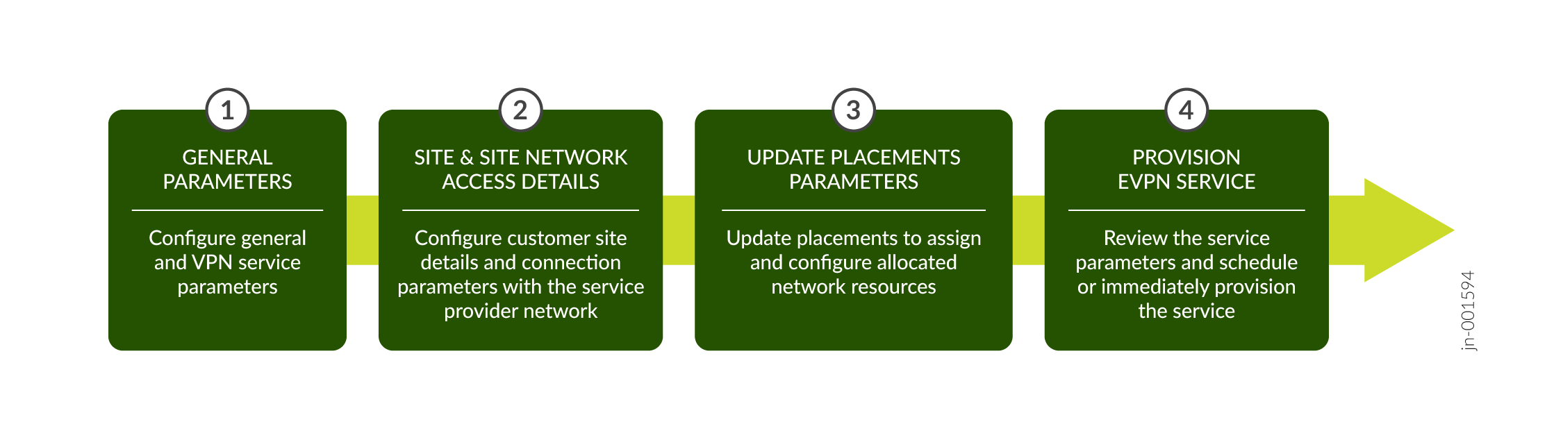
When you create and save an EVPN service instance, Routing Director generates a create service order. After you provision the service instance, Routing Director activates the automated workflow for fulfilling the service order and provisions the service in the network.
You can create an EVPN service instance by uploading preconfigured JSON files or by entering the details in the fields on the Add E-LAN EVPN CSM page.
To create an EVPN service instance:
-
Click Orchestration > Instances.
The Service Instances page appears.
-
Click Add > E-LAN EVPN CSM.
The Add E-LAN EVPN CSM service page appears.
-
On the General page of the Add E-LAN EVPN CSM wizard, enter the values by referring to
the following table:
Note: Fields marked with an asterisk (*) are mandatory.
Table 1: Fields on the General Page (EVPN) Field
Description
Upload JSON File
Click Browse to upload a preconfigured JSON file.
You see a message that the file is successfully imported. The values specified in the file are automatically populated in the corresponding UI fields.
Note:If you are uploading a preconfigured JSON file to create an EVPN service instance, you must clear the placement section in the file before you provision the service order.
Customer*
Enter the name of the customer for whom you are provisioning the service:
-
If you already added the customer name by using the Customer Inventory page (Orchestration > Service > Customers), click the Customer field to see a drop-down with the customer names that you added. Select the customer name from the drop-down list.
-
Alternatively, click the Add Customer link to create a new customer. See Add a Customer.
The customer name must be unique within an organization. For example, network-operator.
Instance Name*
Enter a name for the service instance. For example, irb-evpn-1.
The instance name can be a set of alphanumeric characters and the special character hyphen (-). The maximum number of characters allowed is 64.
VPN Service
VPN Id*
Enter the ID you want to assign to the VPN. For example, vpn10.
The VPN ID must not exceed 64 characters.
VPN Service Topology
Select the topology for the VPN service.
Only the any-to-any topology is supported in this release. In this service topology, all VPN sites can exchange network traffic with each other without any restrictions.
VPN Service Type
Select the service type for EVPN service provisioned by the service provider.
Routing Director supports only the EVPN-MPLS service type.
Route Distinguisher Type
Select the route distinguisher (RD) type. The default RD type is Type 0.
If Type 0 is selected, after the service instance is configured and the placements are updated, the Type 0 values are populated from the VPN resource pool in the Route Distinguishers table at the bottom of the page. If Type 1 is selected, the Type 1 values are populated from the NIP or topo resource pool in the Route Distinguishers table at the bottom of the page.
EVPN Service Type
Select the type of EVPN service:
-
vlan-aware—VLAN-aware supports multiple broadcast domains to map to a single bridge domain. Multiple VLANs are mapped to a single EVPN instance and share the same bridge table in the MAC-VRF table.
Note:-
The VLAN-aware EVPN service type is not supported for untagged interfaces and Q-in-Q tagged interfaces.
-
-
vlan-based—VLAN-based supports a one-to-one mapping of a single broadcast domain to a single bridge domain. Each VLAN is mapped to a single EVPN instance, resulting in a separate bridge table for each VLAN.
The default EVPN service type is vlan-based.
Multiplatform
Switch the Multiplatform toggle to True to enable the VPN service to span multiple device platforms.
The default setting is False.
Note: When Routing Director is upgraded from release 2.5.0 to release 2.6.0, the toggle button is automatically set to true.Pinned Reservation
Configure the service to use reserved resources (pinned resources).
Brownfield
Enable this flag if this is a brownfield service. When enabled, this service would be provisioned by using resources reserved for migrating brownfield services to Routing Director.
Customer
Enable this flag to allow the service to be provisioned by using resources that are exclusively reserved for the customer associated with this service.
Instance
Enable this flag to allow the service to be provisioned by using resources exclusively reserved for this service.
Service Settings
Enter common settings applicable for the service.
Use instance name instead of UUID in device configuration.
Toggle to True to use the service instance name, instead of UUID, in the device configurations. The specified name is used in configuration such as routing instance name, filter name, policer name, community name, policy statement name, and so on. The instance name must be unique across customers and can be a maximum of 32 characters long.
Disable it to set it to False, so that the service instance name is auto-converted to a UUID and used in the device configuration. The UUID is a system generated alphanumeric value.
This option is disabled, by default.
-
-
(Optional) Click Update Placements to assign placement
parameters. You can assign placement parameters for route target, placement IRB, route
distinguishers and placement ESI.
View the updated placement parameters and to optionally edit them:
-
Expand Route Target and configure the placement parameters by referring to the following table:
Table 2: Route Target (EVPN) Field
Description
Number
Enter the number of route targets.
The block size entered when configuring a VPN resource pool is the upper limit for the route target number. The entered block size is displayed to the right of the text box.
Pool
Select a pool value.
The ASN values specified when configuring a VPN resource pool are available as options in the drop-down list.
-
Expand Placement IRB and configure the placement parameters.
Select the PE node and click the edit icon. The Placement IRB page appears.
Configure the placement parameters by referring to the following table:
Table 3: Placement IRB (EVPN) Field
Description
If you selected vlan-based as the EVPN service type:
PE Node
Displays the PE device assigned to the IRB instance.
IRB
Enter the IRB interface ID for the PE device from the available range of interface IDs.
The available range of IRB interface IDs is specified when you configure the topology resource instance and is displayed next to the IRB text box.
If you selected vlan-aware as the EVPN service type:
PE Node
Displays the PE device assigned to the IRB instance.
VLAN
Displays the VLAN ID assigned to the PE device.
IRB
Enter the IRB interface ID for the PE device from the available range of interface IDs.
The available range of IRB interface IDs is specified when you configure the topology resource instance and is displayed next to the IRB text box.
Note: Configuring IRB interfaces for an E-LAN EVPN CSM service is qualified only for the following scenarios:-
EVPN with Ethernet interface port mode.
-
EVPN with Ethernet interface VLAN mode.
-
EVPN with Aggregate Ethernet interface port mode.
-
EVPN with Aggregate Ethernet interface VLAN mode.
-
Multihomed EVPN with Aggregate Ethernet interface port mode.
-
Multihomed EVPN with Aggregate Ethernet interface VLAN mode.
-
-
Expand Route Distinguishers and configure the service instance to see the assigned RDs.
- Select a PE Node and click the edit icon. The Route Distinguisher - Type
selected-type page
appears.
Configure the parameters by referring to the following table:
Table 4: Route Distinguishers (EVPN) Field
Description
If you selected type0 as the Route Distinguisher Type:
PE Node
The name of the PE node device.
Pool
The unique RD identifier configured as the ASN in the VPN resource pool.
When the service is configured, the combination of the pool ID a Routing Director assigned number is visible in the device CLI in the format
pool:number. For example, 60000:9.Number
A unique number assigned to the RD by Routing Director. In the previous example, the number is 9.
If you selected type1 as the Route Distinguisher Type:
PE Node
Name of the PE node device.
IP Address
Loopback address of the device.
If you want to change the loopback address for the device, you can edit the entry from the available preconfigured loopback addresses. To edit, select the RD, click the pencil icon, and select another loopback address from the drop-down list.
Name
Unique RD identifier populated from the configured names in the topo resource instance.
Assigned Number
A unique number assigned to the RD by Routing Director from the block size configured in the topo resource instance.
To change the assigned number, select the RD, click the pencil icon, and edit the number from the preconfigured range visible next to the textbox.
When the service is configured, the combination of the loopback address and the assigned number is visible in the device CLI in the format
loopback_IP:number. For example, 192.168.1.1:30. - Select a PE Node and click the edit icon. The Route Distinguisher - Type
selected-type page
appears.
-
Expand Placement ESI (Ethernet Segment Identifier) and configure the placement parameters.
Select the name of the ESI and click the edit icon. The Placement ESI page appears.
Configure the parameters by referring to the following table:
Table 5: Placement ESI (EVPN) Field
Description
Name
Displays the name of the access diversity group to which the ESI ID is assigned.
VLAN
Displays the VLAN ID of the access interface to which the ESI ID is assigned.
Pool
Select a pool from which the ESI is allocated.
Values
Enter a value for the variable part of the ESI ID within the configured range. If you enter a value outside of the configured range, the page displays an error message.
The variable part of the ESI ID is based on the Start and End values specified in the EVPN ESI section of the L2 Addr resource instance.
For example, if you enter 00:01 as the Start value and 00:05 as the End value, the middle part of the ESI ID will be a value between 00:01 and 00:05.
-
-
Do any of the
following:
Click Next to proceed to the Customer Site Settings page of the Add E-LAN EVPN CSM wizard. See Add EVPN Site and Site Network Access Details.
Click Cancel to discard your changes.
- Configure post update placement parameters for the E-LAN EVPN CSM service. See Add EVPN Service Post Update Placements Site Network Access Parameters.
- View summary of the E-LAN EVPN CSM service and then save and provision the service. See View Summary and Provision an EVPN Service.